Very Cool Parts

Visit our community sponsor

Thanks Thanks:  225
Likes Likes:  220
Page 27 of 30 FirstFirst ... 172526272829 ... LastLast
Results 1,041 to 1,080 of 1172

Thread: Edwardb’s Gen 3 Type 65 Coyote Coupe #59 Build: 5,000 Mile Report

  1. #1041
    Senior Member edwardb's Avatar
    Join Date
    Feb 2011
    Location
    Lake Orion, Michigan
    Posts
    10,577
    Post Thanks / Like
    Quote Originally Posted by Tooth View Post
    You did an amazing job with this car. God willing I'll get to build one of these in the near future, and if it comes out one tenth of what your car is I'll be delighted. I've been flip flopping on building a factory five car for the better part of twenty years now. Biggest hold up is time. I get the bug, can't shake it for a while, then I chicken out. This time it feels different. I just can't shake the need to build one of these this time, and cars like yours are making it really hard to get it out of my head.
    Thanks for the kind words. Come on in! The water's fine. Blast to build and amazing to drive. The Coupe is our favorite FFR build to date. Gets a ton of attention everywhere it goes. Even though it's amazing how many people don't know what it is until you tell the story.
    Build 1: Mk3 Roadster #5125. Sold 11/08/2014. Build 2: Mk4 Roadster #7750. Sold 04/10/2017. Build Thread
    Build 3: Mk4 Roadster 20th Anniversary #8674. Sold 09/07/2020. Build Thread and Video. Build 4: Gen 3 Type 65 Coupe #59. Gen 3 Coyote. Legal 03/04/2020. Build Thread and Video
    Build 5: 35 Hot Rod Truck #138. LS3 and 4L65E auto. Rcvd 01/05/2021. Legal 04/20/2023. Build Thread. Sold 11/9/2023.

  2. #1042
    Senior Member MSumners's Avatar
    Join Date
    Dec 2018
    Location
    Hudsonville, MI
    Posts
    626
    Post Thanks / Like
    Quote Originally Posted by Tooth View Post
    You did an amazing job with this car. God willing I'll get to build one of these in the near future, and if it comes out one tenth of what your car is I'll be delighted. I've been flip flopping on building a factory five car for the better part of twenty years now. Biggest hold up is time. I get the bug, can't shake it for a while, then I chicken out. This time it feels different. I just can't shake the need to build one of these this time, and cars like yours are making it really hard to get it out of my head.
    Don’t let the time factor deter you. I work 60-70 hours most weeks and built a roadster. It took 3 years and just completing but I think you’ll find it’ll go quicker than anticipated, especially with good research. Just do it you won’t regret it.
    Coupe Kit Delivered 11/10/23

    Roadster Build thread: 2019-2022 https://thefactoryfiveforum.com/show...4-Build-Thread

  3. #1043
    Senior Member
    Join Date
    Mar 2021
    Posts
    361
    Post Thanks / Like

    Why two wheels?

    This is a great looking design! I am just wondering why two wheels on each side of your hood / bonnet closure system?

    I have Al plate in hand, and inline skate wheels coming in the mail. Now, the devil is in the details :-)
    Last edited by LateApex; 10-25-2021 at 05:12 PM.

  4. #1044
    Senior Member edwardb's Avatar
    Join Date
    Feb 2011
    Location
    Lake Orion, Michigan
    Posts
    10,577
    Post Thanks / Like
    Quote Originally Posted by LateApex View Post
    This is a great looking design! I am just wondering why two wheels on each side of your hood / bonnet closure system?

    I have Al plate in hand, and inline skate wheels coming in the mail. Now, the devil is in the details :-)
    It might work fine with one wheel per side. Just so happened that the idea I kinda sorta copied had two wheels per side so that's what I did. Keep in mind the wheels not only guide the hood when opening and closing, they also maintain the alignment at the bottom on both sides. Having two wheels gives that much more support. No downside in my opinion.
    Build 1: Mk3 Roadster #5125. Sold 11/08/2014. Build 2: Mk4 Roadster #7750. Sold 04/10/2017. Build Thread
    Build 3: Mk4 Roadster 20th Anniversary #8674. Sold 09/07/2020. Build Thread and Video. Build 4: Gen 3 Type 65 Coupe #59. Gen 3 Coyote. Legal 03/04/2020. Build Thread and Video
    Build 5: 35 Hot Rod Truck #138. LS3 and 4L65E auto. Rcvd 01/05/2021. Legal 04/20/2023. Build Thread. Sold 11/9/2023.

  5. #1045
    Member
    Join Date
    Mar 2021
    Location
    Mission Viejo Ca.
    Posts
    72
    Post Thanks / Like
    Hi Paul. do you have the demensions posted for your Hood Roller Brackets? I would like to make them while I have the Body off my Gen 3 Chassi.

  6. #1046
    Senior Member edwardb's Avatar
    Join Date
    Feb 2011
    Location
    Lake Orion, Michigan
    Posts
    10,577
    Post Thanks / Like
    Quote Originally Posted by B Campbell View Post
    Hi Paul. do you have the demensions posted for your Hood Roller Brackets? I would like to make them while I have the Body off my Gen 3 Chassi.
    I posted a tracing of the prototype pieces I still had around at the time. With a 6" ruler in the picture. This should be enough to duplicate them. https://thefactoryfiveforum.com/show...l=1#post400154.
    Build 1: Mk3 Roadster #5125. Sold 11/08/2014. Build 2: Mk4 Roadster #7750. Sold 04/10/2017. Build Thread
    Build 3: Mk4 Roadster 20th Anniversary #8674. Sold 09/07/2020. Build Thread and Video. Build 4: Gen 3 Type 65 Coupe #59. Gen 3 Coyote. Legal 03/04/2020. Build Thread and Video
    Build 5: 35 Hot Rod Truck #138. LS3 and 4L65E auto. Rcvd 01/05/2021. Legal 04/20/2023. Build Thread. Sold 11/9/2023.

  7. #1047
    Junior Member
    Join Date
    Nov 2021
    Posts
    11
    Post Thanks / Like
    Howdy! I run a fabrication shop in South Jersey, and we make a lot of things out of aluminum, mostly for the military. 6061 is a stronger alloy with higher tensile strength than 5052, but it's much more proned to cracking, especially as thickness increases, (1/8"+) and/or if too tight of a radius is used on the forming dies. Also forming a 45° for instance you can get away with on 6061 but trying to bend a tight 90° you run the risk of cracking. Annealing the bend area is another trick you can use to form harder alloys, but your effectively reducing the tensile strength in that area which raises the question, why use such a hard alloy in the first place. Anywho, most of our aluminum that needs forming is 5052 and the rest that's only sheared/punched/machined but not bent is 6061. At 0.040" thick though, i think you can bend just about any alloy of aluminum without issue, but since your box isn't a structural part, i would have chosen 5052 for easier working. BTW, thank you for your incredible documentation of your build. I know I'm a few years late to the party, but it's a tremendous resource you've put up here. Thank you!

  8. #1048
    Senior Member edwardb's Avatar
    Join Date
    Feb 2011
    Location
    Lake Orion, Michigan
    Posts
    10,577
    Post Thanks / Like
    Quote Originally Posted by CB_83 View Post
    Howdy! I run a fabrication shop in South Jersey, and we make a lot of things out of aluminum, mostly for the military. 6061 is a stronger alloy with higher tensile strength than 5052, but it's much more proned to cracking, especially as thickness increases, (1/8"+) and/or if too tight of a radius is used on the forming dies. Also forming a 45° for instance you can get away with on 6061 but trying to bend a tight 90° you run the risk of cracking. Annealing the bend area is another trick you can use to form harder alloys, but your effectively reducing the tensile strength in that area which raises the question, why use such a hard alloy in the first place. Anywho, most of our aluminum that needs forming is 5052 and the rest that's only sheared/punched/machined but not bent is 6061. At 0.040" thick though, i think you can bend just about any alloy of aluminum without issue, but since your box isn't a structural part, i would have chosen 5052 for easier working. BTW, thank you for your incredible documentation of your build. I know I'm a few years late to the party, but it's a tremendous resource you've put up here. Thank you!
    Factory Five uses 6061 exclusively for their kits. Mainly .040" and bend multiple angles up and and in some cases beyond 90 degrees. I've not experienced or heard of any issues with cracking with their parts. Clearly they know what they're doing. As far as the parts I've fabricated, I use what material I can get my hands on. Sometimes 6061. Other times 5052 from a local metal supplier. I am aware of the limitations and take necessary precautions. Having said that, the few parts I've fabricated (storage box, instrument panel switch box, glovebox, etc.) are not structural so no worries. Not my first time around this stuff. Since this build thread was posted, I've acquired a Woodward Fab box break, so have even a better handle on this. Glad you appreciated the build thread.
    Last edited by edwardb; 11-27-2021 at 08:01 AM.
    Build 1: Mk3 Roadster #5125. Sold 11/08/2014. Build 2: Mk4 Roadster #7750. Sold 04/10/2017. Build Thread
    Build 3: Mk4 Roadster 20th Anniversary #8674. Sold 09/07/2020. Build Thread and Video. Build 4: Gen 3 Type 65 Coupe #59. Gen 3 Coyote. Legal 03/04/2020. Build Thread and Video
    Build 5: 35 Hot Rod Truck #138. LS3 and 4L65E auto. Rcvd 01/05/2021. Legal 04/20/2023. Build Thread. Sold 11/9/2023.

  9. #1049
    Senior Member
    Join Date
    Jun 2019
    Location
    Whitehouse TX
    Posts
    276
    Post Thanks / Like
    Any idea where to get the part numbers for the vacuum connectors? Need to see exactly where to hook them up.

  10. #1050
    Senior Member
    Join Date
    May 2019
    Posts
    226
    Post Thanks / Like
    Quote Originally Posted by edwardb View Post
    It might work fine with one wheel per side. Just so happened that the idea I kinda sorta copied had two wheels per side so that's what I did. Keep in mind the wheels not only guide the hood when opening and closing, they also maintain the alignment at the bottom on both sides. Having two wheels gives that much more support. No downside in my opinion.
    Looking at this guide wheel and bracket you fab'd, which obviously works just fine, it looks to me like a simpler solution would be a 90 degree bracket that would bolt on with the latch u-bolt, outside of the inner aluminum panel, looks to me like an easier way to do it.

  11. #1051
    Senior Member
    Join Date
    Dec 2016
    Posts
    323
    Post Thanks / Like
    Quote Originally Posted by Ltngdrvr View Post
    Looking at this guide wheel and bracket you fab'd, which obviously works just fine, it looks to me like a simpler solution would be a 90 degree bracket that would bolt on with the latch u-bolt, outside of the inner aluminum panel, looks to me like an easier way to do it.
    If you make set like that, please make another set for me - or share the CAD file!

    Thanks,
    Dave

    Gen III #17

  12. #1052
    Senior Member edwardb's Avatar
    Join Date
    Feb 2011
    Location
    Lake Orion, Michigan
    Posts
    10,577
    Post Thanks / Like
    Quote Originally Posted by Ltngdrvr View Post
    Looking at this guide wheel and bracket you fab'd, which obviously works just fine, it looks to me like a simpler solution would be a 90 degree bracket that would bolt on with the latch u-bolt, outside of the inner aluminum panel, looks to me like an easier way to do it.
    Quote Originally Posted by Dave Tabor View Post
    If you make set like that, please make another set for me - or share the CAD file!

    Thanks,
    Dave

    Gen III #17
    I never claimed my solution was the only way. As mentioned, mine is loosely based on versions I saw for previous gen Coupes. I don't see any reason why using the hood latch U-bolts wouldn't also work as an attachment point. Probably needs to be from steel versus the 1/8" aluminum I used. There's quite a bit of stress pushing against the wheels. Not sure a 90 degree bend in aluminum would be stiff enough. You would need to make sure you're offset far enough from the latch mechanism in the hood. It's obviously necessary for the wheels to be rolling on a smooth interrupted area of the hood underside. You'll also need to build in some way to adjust to get the wheels in just the right place. Someone suggested to put slots where the wheels attached. At least for the wheels I used, that wouldn't work. When tightened enough to not move in a slot they wouldn't turn. So I have slots on the inner part of the bracket and easy to adjust there by sliding the whole assembly.

    Last edited by edwardb; 02-07-2022 at 03:02 PM.
    Build 1: Mk3 Roadster #5125. Sold 11/08/2014. Build 2: Mk4 Roadster #7750. Sold 04/10/2017. Build Thread
    Build 3: Mk4 Roadster 20th Anniversary #8674. Sold 09/07/2020. Build Thread and Video. Build 4: Gen 3 Type 65 Coupe #59. Gen 3 Coyote. Legal 03/04/2020. Build Thread and Video
    Build 5: 35 Hot Rod Truck #138. LS3 and 4L65E auto. Rcvd 01/05/2021. Legal 04/20/2023. Build Thread. Sold 11/9/2023.

  13. Likes cgundermann liked this post
  14. #1053
    Senior Member
    Join Date
    Aug 2019
    Location
    Paradise/Magalia Ca
    Posts
    187
    Post Thanks / Like
    Just went thru your pics
    this car and all your builds are beautiful

  15. Thanks edwardb thanked for this post
  16. #1054
    Junior Member
    Join Date
    Aug 2012
    Location
    Mount Dora FL
    Posts
    25
    Post Thanks / Like
    Hi Paul,
    If you wouldn't mind, could you provide me the correct P/N and source for the Eibach 1" wheel spacers?

    Thank you,
    Tim
    Mount Dora FL

  17. #1055
    Namrups's Avatar
    Join Date
    Sep 2021
    Location
    Mechanicville, NY
    Posts
    1,018
    Post Thanks / Like
    Tim, Follow this link. It is an album I have started that lists custom parts and tools, where to order them and what I paid for them. Most of these I also got from Pauls builds. Hope it helps.
    https://thefactoryfiveforum.com/album.php?albumid=2045
    Scott Pregont
    Present build: 65 Daytona Coupe #393 - Forte 427 EFI crate w/TKX 2.87/ .81 - Ordered 11/16/21 - Delivered 6/23/2022
    Location: Mechanicville, NY
    Build Thread: https://thefactoryfiveforum.com/show...na-Coupe-build
    My Albums
    Special Tools, Custom Parts, misc supplies: https://thefactoryfiveforum.com/album.php?albumid=2045
    Garage Pics: https://thefactoryfiveforum.com/album.php?albumid=2041
    POR15 First Try: https://thefactoryfiveforum.com/album.php?albumid=2068
    Silicone application tips: https://thefactoryfiveforum.com/album.php?albumid=2063

  18. #1056
    Senior Member edwardb's Avatar
    Join Date
    Feb 2011
    Location
    Lake Orion, Michigan
    Posts
    10,577
    Post Thanks / Like
    Quote Originally Posted by mtdr View Post
    Hi Paul,
    If you wouldn't mind, could you provide me the correct P/N and source for the Eibach 1" wheel spacers?

    Thank you,
    Tim
    Mount Dora FL
    They're Eibach 90.4.25.010.3 Pro-Spacer Wheel Spacer Kit, 25mm (1 inch), 70.50mm diameter, 1/2-20 thread size. Also pictured in Namrups gallery (nice, BTW). I bought them on Amazon four years ago. Looks like they still may have them available. But showing not available lots of other places. For my truck build, also needed 1 inch spacers and couldn't find the Eibach ones anywhere at that time. So did some looking and ended up with Coyote brand WHSP24 5450-5450-A, 6061 Billet Aluminum, Black Anodize, 5x4.50 - 5x4.50, 1.00", HC 70.50m, 1/2-20 thread size from CJ Pony Parts. I don't know that they're quite the quality of the Eibach ones. But about half the price and still hub centric. I'm more than happy with them as an alternative.
    Build 1: Mk3 Roadster #5125. Sold 11/08/2014. Build 2: Mk4 Roadster #7750. Sold 04/10/2017. Build Thread
    Build 3: Mk4 Roadster 20th Anniversary #8674. Sold 09/07/2020. Build Thread and Video. Build 4: Gen 3 Type 65 Coupe #59. Gen 3 Coyote. Legal 03/04/2020. Build Thread and Video
    Build 5: 35 Hot Rod Truck #138. LS3 and 4L65E auto. Rcvd 01/05/2021. Legal 04/20/2023. Build Thread. Sold 11/9/2023.

  19. #1057
    Senior Member lewma's Avatar
    Join Date
    Jan 2018
    Location
    San Marcos, CA
    Posts
    448
    Post Thanks / Like
    Blog Entries
    1
    All, incase the Eibach spacers are hard to find. I ordered a set of these from Amazon and they arrived yesterday. Look to be a decent product and fit the hubs fine:

    https://www.amazon.com/GAsupply-Cent...ct_top?ie=UTF8

    mark
    Build 1: Mk4 Complete Kit #9312 Ordered 1/27/18, Delivered 3/24/18, CA SB100 Registered 9/11/19 - Gen 2 Coyote TKO600, IRS, Power Steering, Wilwood Brakes, 17" Halibrand.
    Build 2: Gen3 Coupe Complete Kit #309 Ordered 1/25/21, Delivered 6/9/21 - BluePrint GM 427 LS T56, IRS, AC, Power Steering. Album Here

  20. Likes cgundermann liked this post
  21. #1058
    Senior Member edwardb's Avatar
    Join Date
    Feb 2011
    Location
    Lake Orion, Michigan
    Posts
    10,577
    Post Thanks / Like

    Windshield Replacement

    Not sure I've mentioned here. But have on other threads. Last August, while out cruising with our son, took a large rock or whatever off the windshield at the top driver side corner. Was a pretty sickening sound... Not long after, a crack started down from the divot left by whatever hit us. Ugh. I have glass coverage on my insurance, so cost wasn't a big concern. But sure wasn't looking forward to the effort required to remove and replace. No regular commercial shops, at least around here, will touch this. And I'm not sure I'd want them to. After looking at several options, went ahead and ordered a replacement from Factory Five. It's a 1986 Jaguar XJS windshield. Based on the brief research I did, not widely available plus I didn't want to risk not fitting. So placed my order with FF. Took a while to arrive. But didn't matter because I was able to drive the car the rest of the season and planned for it to be a winter project to replace. Today (finally...) it's done. I'm very fortunate to have a fellow club member who was in the OE automotive glass business. He's retired, but still helped along with a co-worker who's still at it. The same two guys that helped me install the glass during the original build. Of course this time had the added effort of removing the old one. Which was interesting to say the least. I know very little about this kind of thing. So tried to help and learn but mostly stayed out of the way. I won't describe the entire installation process since I did earlier in the build thread. But two takeaways. Beyond just avoiding those Michigan rocks or road hazards in the future.

    1. I chose to use the Flexline UM1913BR 19mm trim rubber on the original build. I liked the cleaner look plus the windshield doesn't have polished edges and the fit in the body is slightly uneven. So made that decision early on. Well, that made removing the windshield quite an additional chore. The guys used a system that puts a wire around the perimeter of the windshield and then a winding mechanism on the inside that pulls the wire through the adhesive. Freeing the windshield. Bunch of YouTube videos showing how this works if you're interested. We had to cut the trim rubber off and out of the groove (as much as we could...) in order to get the wire down where it needed to be. Wasn't that hard. But stressful working around the painted body with sharp instruments. Plus there's gooey black butyl in the groove of the trim rubber that gets everywhere once you start cutting into it. What a mess! But got it done with no visible damage and finally got the windshield out.

    2. The curve of the original windshield didn't match the curve of the body quite right. When set in place, was 1/2" or more high on both ends. Required it to be strapped down to get it to fit. Multiple other builders noted the same thing. So not unique to my build. Once the old windshield was out, checked the fit of the replacement. It was much better. Within 1/8" or maybe a little more and could have probably been taped down if I wasn't using the rubber trim. Don't know if FF changed something with the supplier. The replacement windshield has the same DOT code as the original. So from the same mfg. I know this windshield is from a recent shipment. So at least a couple years newer. Or maybe the fiberglass body had moved/changed and is now more conformed to the windshield. Bottom line a lot better. Once everything was cleaned up and the old urethane cut out of the opening, masked and painted the frit on the windshield with the same Dow Black Betaprime 5504G as used before. Installed the new rubber trim, put a V-bead of Dow Betaseal U-428 Plus adhesive around the opening, and pushed the new windshield into place. Strapped the windshield down the same as before, but didn't have to use nearly as much pressure. Actually pretty light. Mainly was necessary to get the rubber trim to drop down into place. It just barely fits. I let it cure for a couple days as suggested and today removed the straps and put everything back together.

    Summary: If I ever build another Coupe, I will probably not use the trim rubber. It complicates the installation. If you're unlucky like me and get to replace the windshield, makes that process more complicated too. I briefly considered not using it on the replacement windshield. But I was already committed plus the cut-out of the windshield didn't do any favors to the perimeter of the body that's covered with the trim in place. I for sure won't be using any on the front and rear glass of the truck build I'm working on now.

    That's it. Now let the driving season begin.


    Last edited by edwardb; 08-15-2022 at 04:52 AM.
    Build 1: Mk3 Roadster #5125. Sold 11/08/2014. Build 2: Mk4 Roadster #7750. Sold 04/10/2017. Build Thread
    Build 3: Mk4 Roadster 20th Anniversary #8674. Sold 09/07/2020. Build Thread and Video. Build 4: Gen 3 Type 65 Coupe #59. Gen 3 Coyote. Legal 03/04/2020. Build Thread and Video
    Build 5: 35 Hot Rod Truck #138. LS3 and 4L65E auto. Rcvd 01/05/2021. Legal 04/20/2023. Build Thread. Sold 11/9/2023.

  22. Thanks MSumners, Windsor thanked for this post
  23. #1059
    Member James Morse's Avatar
    Join Date
    Feb 2020
    Location
    SW Virginia
    Posts
    32
    Post Thanks / Like
    Super nice result though, Paul, after all the work. I had a question, you mentioned the first windshield being quite a bit off as to meeting the body and about strapping them (old and new) down. When this is done, are you actually bending the windshield to fit or is it pushing the rubber down in the middle so the edges fit, or what? I can't imagine the glass bending to fit, plus then it would be under stress to pop out... so there must be something I'm not understanding about it.

    Thanks for the terrific write up and pics.

  24. #1060
    Senior Member
    Join Date
    May 2019
    Posts
    226
    Post Thanks / Like
    Quote Originally Posted by James Morse View Post
    Super nice result though, Paul, after all the work. I had a question, you mentioned the first windshield being quite a bit off as to meeting the body and about strapping them (old and new) down. When this is done, are you actually bending the windshield to fit or is it pushing the rubber down in the middle so the edges fit, or what? I can't imagine the glass bending to fit, plus then it would be under stress to pop out... so there must be something I'm not understanding about it.

    Thanks for the terrific write up and pics.
    The windshield bends, and the adhesive is very strong.
    You'd be surprised how much the windshield will flex.

  25. Thanks James Morse thanked for this post
  26. #1061
    Senior Member edwardb's Avatar
    Join Date
    Feb 2011
    Location
    Lake Orion, Michigan
    Posts
    10,577
    Post Thanks / Like
    Quote Originally Posted by James Morse View Post
    Super nice result though, Paul, after all the work. I had a question, you mentioned the first windshield being quite a bit off as to meeting the body and about strapping them (old and new) down. When this is done, are you actually bending the windshield to fit or is it pushing the rubber down in the middle so the edges fit, or what? I can't imagine the glass bending to fit, plus then it would be under stress to pop out... so there must be something I'm not understanding about it.

    Thanks for the terrific write up and pics.
    Quote Originally Posted by Ltngdrvr View Post
    The windshield bends, and the adhesive is very strong.
    You'd be surprised how much the windshield will flex.
    What he said. The windshield bends. As I think everyone knows, it's safety glass so two rather thin layers of glass with plastic between. Total thickness is under 1/4 inch. So relatively flexible. And that urethane adhesive, properly applied with primer, etc. is amazingly strong. But on the original installation, with or without the rubber trim, something was needed to seat the windshield on the ends until the adhesive cured. Thus the straps and padded blocks. Others doing builds at the same time were doing the same thing. That's where I got the idea. The replacement windshield was close enough that it probably could have been just pushed into place and taped were it not for the rubber trim. Hopefully guys doing new builds will have a similar fit. It's easier and a lot less stressful.
    Last edited by edwardb; 04-02-2022 at 04:23 PM.
    Build 1: Mk3 Roadster #5125. Sold 11/08/2014. Build 2: Mk4 Roadster #7750. Sold 04/10/2017. Build Thread
    Build 3: Mk4 Roadster 20th Anniversary #8674. Sold 09/07/2020. Build Thread and Video. Build 4: Gen 3 Type 65 Coupe #59. Gen 3 Coyote. Legal 03/04/2020. Build Thread and Video
    Build 5: 35 Hot Rod Truck #138. LS3 and 4L65E auto. Rcvd 01/05/2021. Legal 04/20/2023. Build Thread. Sold 11/9/2023.

  27. Thanks James Morse thanked for this post
  28. #1062
    Senior Member
    Join Date
    Aug 2019
    Location
    Paradise/Magalia Ca
    Posts
    187
    Post Thanks / Like
    edwardb I'm getting ready to remove my body off my coupe r and with all those extra bars i worry about cracking the fiberglass any suggestions thanks james
    i sent you a private message also
    Last edited by jamminj; 04-30-2022 at 02:48 PM.

  29. #1063
    Senior Member edwardb's Avatar
    Join Date
    Feb 2011
    Location
    Lake Orion, Michigan
    Posts
    10,577
    Post Thanks / Like
    Quote Originally Posted by jamminj View Post
    edwardb I'm getting ready to remove my body off my coupe r and with all those extra bars i worry about cracking the fiberglass any suggestions thanks james
    i sent you a private message also
    This build isn't an R Coupe. I haven't even seen one in person. So pretty hesitant to offer advice for something I have no experience or knowledge of. Just looking at the chassis pictures on the FF website, looks like the main bars affecting the main body shell would be the added bars across the door openings. But again, that's just an observation. Not advice. I will tell you the bodies in general are more flexible than you might think and within reason not prone to cracking. Keep in mind the guys at FF that prepped your kit for shipping dropped it on there. Mainly I would suggest to have as much help as possible so you can lift and spread it as evenly and carefully as possible. Also, if you have a powder coated frame, might want to have some towels and/or rags available to pad the chassis when taking the body on and off. Keeps from scratching things up.
    Build 1: Mk3 Roadster #5125. Sold 11/08/2014. Build 2: Mk4 Roadster #7750. Sold 04/10/2017. Build Thread
    Build 3: Mk4 Roadster 20th Anniversary #8674. Sold 09/07/2020. Build Thread and Video. Build 4: Gen 3 Type 65 Coupe #59. Gen 3 Coyote. Legal 03/04/2020. Build Thread and Video
    Build 5: 35 Hot Rod Truck #138. LS3 and 4L65E auto. Rcvd 01/05/2021. Legal 04/20/2023. Build Thread. Sold 11/9/2023.

  30. #1064
    Senior Member
    Join Date
    Aug 2019
    Location
    Paradise/Magalia Ca
    Posts
    187
    Post Thanks / Like
    i knew yours wasn't a type r but i appreciate any input
    thank you
    unfortunately, it came all scratched up they chewed it up putting the aluminum panels in but i will try my best not to make it worse

  31. #1065
    Senior Member
    Join Date
    Aug 2019
    Location
    Paradise/Magalia Ca
    Posts
    187
    Post Thanks / Like
    body is off wow lots of flexing

  32. #1066
    Senior Member
    Join Date
    Mar 2021
    Location
    Ohio
    Posts
    279
    Post Thanks / Like
    Quote Originally Posted by edwardb View Post
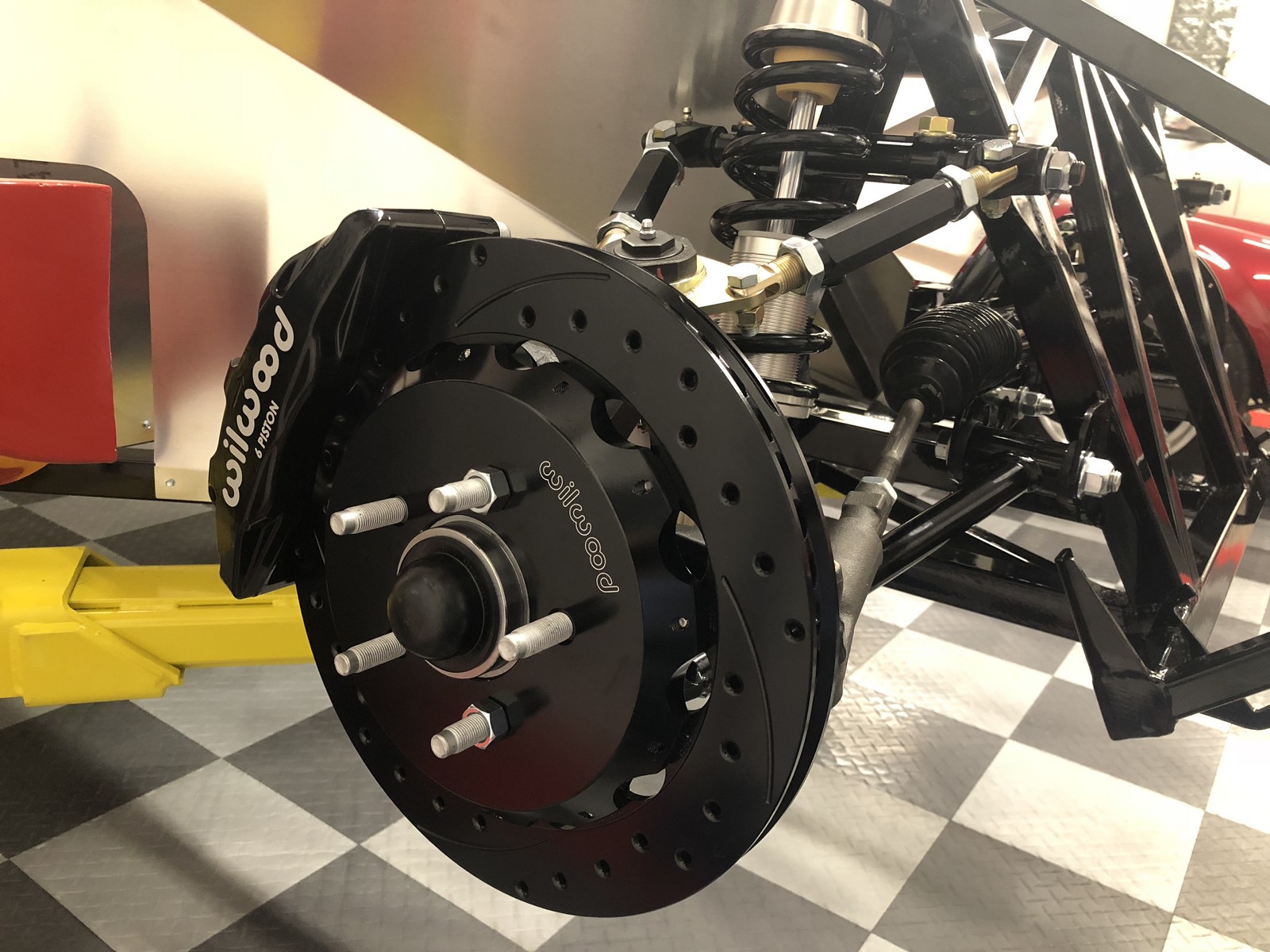
    The front suspension is completely assembled except for the sway bar. Missing the sway bar bushings so can’t finish it yet. Everything else is done. The front suspension uses all the same components as the Roadster, so nothing too earthshaking here. Had to remove powder coat from holes, spread the tabs a bit on a couple, and adjust one of the holes just slightly on one LCA tab to get it to line up. Other than that, went together very normally and everything fit perfectly. I put grease into the LCA and UCA pivots before assembly. Confirms they are greased properly right from the start, plus makes them go together a little easier. I used a paint marker to indicate final torque completed as I went. For the upper ball joints, also put witness marks to monitor they aren’t moving.

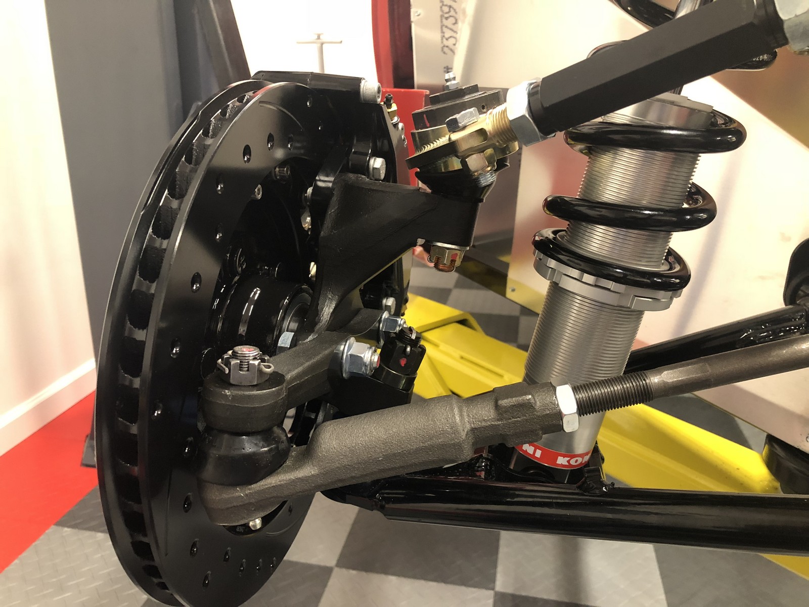
    As mentioned before, did use Howe Racing 22320S ball joints. Also switched the upper ball joint and tie rod ends to Energy Suspension boots. I used the Breeze 3-turn Unisteer power steering rack. Before putting in the coilovers, I propped the suspension up to approximate ride height and tried to get the alignment a little in the ball park. On the UCA, have the front adjuster out 2-3 times as much as the rear one for caster, used a level on the brake disks and adjusted to -.5 degrees camber, then used a laser pointer on the brake disks to get the toe relatively straight to the chassis. Probably won’t be all that close when it’s time for the real alignment. But hopefully not totally random. I don’t have the brakes completely assembled yet. I’ll do the safety wires and finalize everything at the same time as the rear brakes. From earlier today:


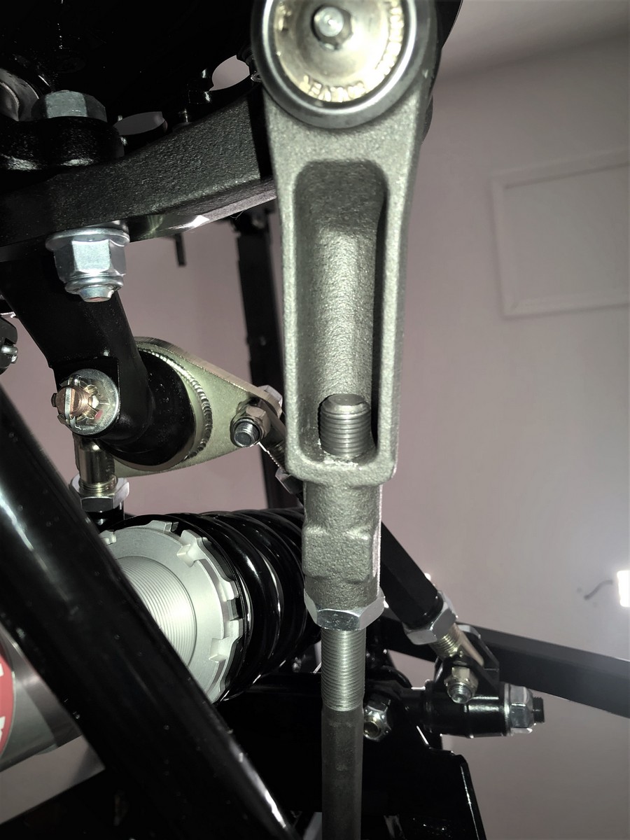
    The last picture shows the Moog ES2150RL tie rod ends I’ve used on all my builds. They’re nice quality pieces, and I especially like how the threaded ends come through to the inside. Makes it real easy to confirm you have proper thread engagement. Plus eliminates having to trim the ends.

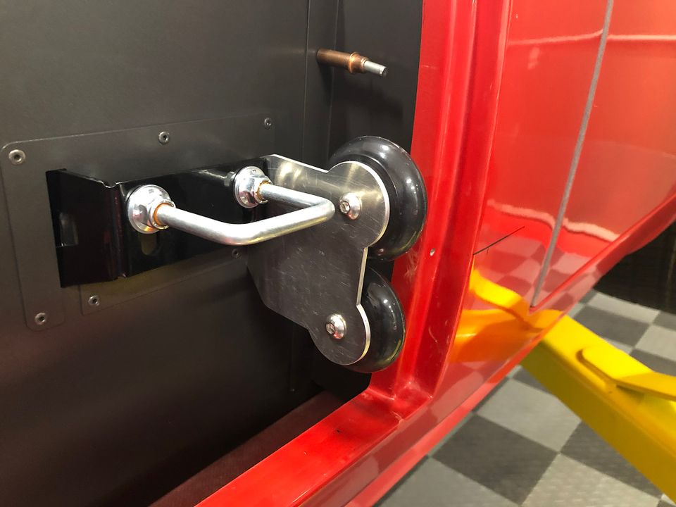
    Several observations from the assembly specific to the Coupe. Factory Five provides two sets of holes for all the components including the steering rack. The lower holes for street use, the upper for racing use. I used all the lower holes except at the last minute noticed the instructions said to use the upper holes for the upper coilover mount if using the double action Koni’s like I have. Good thing I read the instructions. I changed the direction of the bolt installation for the front LCA mount and the steering rack. Installed like shown in the instructions would have made them difficult if not impossible to remove once the radiator is installed. On the Anniversary Roadster #8674 build, also with the Koni double action shocks, I had to trim where the shocks mount on the LCA to eliminate interference. Wasn’t necessary this time. FF changed the mount tabs so they no longer interfere. Continuous improvement! Way to go.

    I also installed the steering column so I could center up the rack when installing and connecting the tie rod ends. Found out that I again had to mount the footbox steering shaft bearing on the inside of the footbox. Same as the Anniversary Roadster build, which had the same Breeze Unisteer power rack. Apparently that input shaft is slightly long. It’s not possible to get the steering shaft onto the rack input with the bearing on the outside of the footbox. Had to trim the bearing shells slightly along one edge, but other than that, no problem with it being inside. Another thing I noticed is Unisteer is now putting a groove around the entire diameter of the input shaft for the adapter set screw. So no matter where you orient it, the set screw drops into it. This is different than before (and most other racks) that just have a single cutout for the set screw. Then guys start wondering what to do when the steering wheel won't center with the rack.


    Next up is to get the center section prepped and installed. Still don’t have IRS control arms, so won’t be able to do too much more there until they arrive. Hopefully soon. Plenty of other stuff to keep working on.

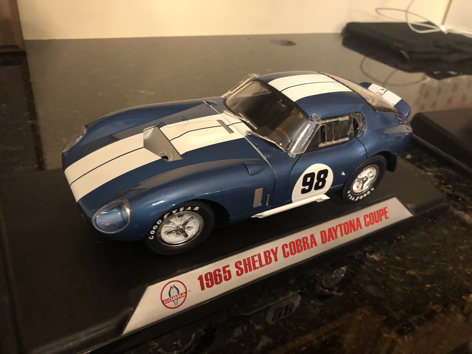
    My son gave me this very cool 1:18 scale Daytona Coupe die-cast model for Christmas. Pretty well known model of the Coupe. I have the Cobra version already, so they’re a matched set. Well, except it's red. He said something about showing me how the Coupe needs to be blue. We’ll see.

    Paul,
    I am working on planning my build, while I wait for my kit to arrive, what made you use the Breeze 3-turn Unisteer power steering rack vs the one from Factory Five?

  33. #1067
    Senior Member edwardb's Avatar
    Join Date
    Feb 2011
    Location
    Lake Orion, Michigan
    Posts
    10,577
    Post Thanks / Like
    Quote Originally Posted by burchfieldb View Post
    Paul, I am working on planning my build, while I wait for my kit to arrive, what made you use the Breeze 3-turn Unisteer power steering rack vs the one from Factory Five?
    Back when I did the 20th Anniversary Roadster Factory Five either didn't have a PS rack or were just offering it. Don't remember. Based on several recommendations, I purchased a Unisteer (Maval Industries) rack from Breeze. Was very happy with it so just duplicated that same rack on the Coupe. It's a moot point though, because Breeze doesn't offer it any more. Mark recommends a new rack from BBB Industries (a buddy just talked to him) but doesn't sell them. Many use reman Fox Mustang racks from their local parts stores. Cheap and lifetime warranties typically. Some have good luck with them. Some not. Of course the PS rack Factory Five offers is certainly an option. I personally don't have any experience with them though. There are other high-end racks, like Flaming River, but no experience with them either. Multiple choices...
    Last edited by edwardb; 07-18-2022 at 03:39 PM.
    Build 1: Mk3 Roadster #5125. Sold 11/08/2014. Build 2: Mk4 Roadster #7750. Sold 04/10/2017. Build Thread
    Build 3: Mk4 Roadster 20th Anniversary #8674. Sold 09/07/2020. Build Thread and Video. Build 4: Gen 3 Type 65 Coupe #59. Gen 3 Coyote. Legal 03/04/2020. Build Thread and Video
    Build 5: 35 Hot Rod Truck #138. LS3 and 4L65E auto. Rcvd 01/05/2021. Legal 04/20/2023. Build Thread. Sold 11/9/2023.

  34. #1068
    Senior Member
    Join Date
    Mar 2021
    Location
    Ohio
    Posts
    279
    Post Thanks / Like
    Good to know, thanks for the knowledge.

  35. #1069
    Senior Member
    Join Date
    Mar 2021
    Posts
    361
    Post Thanks / Like
    Hi Paul -

    You probably have had as many comments or questions on this design point as you can stand. Here is one (or two) more. BTW, this is all because you have a great design here :-)

    1) Why two wheels? As opposed to one? I am thinking that with the locating pins at the fore of the pontoons, once one gets the bonnet lip past the U-joints, maybe a second wheel is not needed, as the pins help? Did you find that because of the slight flair or the bonnet, a little more support from the bottom wheel helped?

    2) I believe I saw a comment you made on this topic concerning the amount of pressure on the wheel as motivation for affixing the aluminum strut (if you will) to the rear surface of the U-bolt bracket/support feature. I am considering using the U-bolt support as the mounting base for an L-shaped strut that has a 90-degree bend, where the wheel (or wheels) can be mounted aft of the U-bolt. My thinking is that the "L" plate can be shimmed with lock nuts on the U-Bolt to give the adjustment or pressure needed on the bonnet.

    I am wondering what your thoughts are concerning use of one wheel, and/or use of an L-shaped wheel mounting bracket. Was this an option you looked at?

    I am getting my body back from painting in a week. Working on these last bits of fitment :-)

    Thx in advance!!

    ... Bob

  36. #1070
    Senior Member edwardb's Avatar
    Join Date
    Feb 2011
    Location
    Lake Orion, Michigan
    Posts
    10,577
    Post Thanks / Like
    Quote Originally Posted by LateApex View Post
    Hi Paul -

    You probably have had as many comments or questions on this design point as you can stand. Here is one (or two) more. BTW, this is all because you have a great design here :-)

    1) Why two wheels? As opposed to one? I am thinking that with the locating pins at the fore of the pontoons, once one gets the bonnet lip past the U-joints, maybe a second wheel is not needed, as the pins help? Did you find that because of the slight flair or the bonnet, a little more support from the bottom wheel helped?

    2) I believe I saw a comment you made on this topic concerning the amount of pressure on the wheel as motivation for affixing the aluminum strut (if you will) to the rear surface of the U-bolt bracket/support feature. I am considering using the U-bolt support as the mounting base for an L-shaped strut that has a 90-degree bend, where the wheel (or wheels) can be mounted aft of the U-bolt. My thinking is that the "L" plate can be shimmed with lock nuts on the U-Bolt to give the adjustment or pressure needed on the bonnet.

    I am wondering what your thoughts are concerning use of one wheel, and/or use of an L-shaped wheel mounting bracket. Was this an option you looked at?

    I am getting my body back from painting in a week. Working on these last bits of fitment :-)

    Thx in advance!!

    ... Bob
    Hi Bob. Thanks for the shout out for the design. But truthfully it's my take on a similar design Whitby's offered for the previous generation Coupes. Which they attribute to Don Vaught. There's no longer a picture on their website however. Those Coupes had a different design for the U-bolt attachment. So I changed the design somewhat to bolt them to the side of the Gen 3 U-bolt mount as shown. I found the U-bolt adjustment is relatively critical (and sensitive) to the alignment of the cowl (bonnet, hood, whatever...) so I didn't want to mess with that to adjust the rollers. That led me to keep the mounting separate from the U-bolt. Again similar to the earlier design. Having said that, no reason to think this is the only way to do it. I suspect what you're describing would work. A single wheel likely would work as well. After all, it's mainly just replacing one bumper. But the location would need to be right. High enough to catch the cowl as it's coming down and position for the alignment pins in the pontoons. And low enough to keep the cowl properly aligned to the body, e.g. replacing the lowest bumper that was removed. Again, I was adopting another design that used two wheels on each side, and to be honest never questioned that aspect. Good luck with yours.
    Build 1: Mk3 Roadster #5125. Sold 11/08/2014. Build 2: Mk4 Roadster #7750. Sold 04/10/2017. Build Thread
    Build 3: Mk4 Roadster 20th Anniversary #8674. Sold 09/07/2020. Build Thread and Video. Build 4: Gen 3 Type 65 Coupe #59. Gen 3 Coyote. Legal 03/04/2020. Build Thread and Video
    Build 5: 35 Hot Rod Truck #138. LS3 and 4L65E auto. Rcvd 01/05/2021. Legal 04/20/2023. Build Thread. Sold 11/9/2023.

  37. Thanks LateApex thanked for this post
  38. #1071
    Senior Member
    Join Date
    Mar 2011
    Location
    Houston
    Posts
    477
    Post Thanks / Like
    Quote Originally Posted by edwardb View Post
    Hi Bob. Thanks for the shout out for the design. But truthfully it's my take on a similar design Whitby's offered for the previous generation Coupes. Which they attribute to Don Vaught. There's no longer a picture on their website however. Those Coupes had a different design for the U-bolt attachment. So I changed the design somewhat to bolt them to the side of the Gen 3 U-bolt mount as shown. I found the U-bolt adjustment is relatively critical (and sensitive) to the alignment of the cowl (bonnet, hood, whatever...) so I didn't want to mess with that to adjust the rollers. That led me to keep the mounting separate from the U-bolt. Again similar to the earlier design. Having said that, no reason to think this is the only way to do it. I suspect what you're describing would work. A single wheel likely would work as well. After all, it's mainly just replacing one bumper. But the location would need to be right. High enough to catch the cowl as it's coming down and position for the alignment pins in the pontoons. And low enough to keep the cowl properly aligned to the body, e.g. replacing the lowest bumper that was removed. Again, I was adopting another design that used two wheels on each side, and to be honest never questioned that aspect. Good luck with yours.
    Since the skirt of the hood 1. Bowed and 2. Does not come down vertically, but in an arc.
    I made a simple setup which is adjustable and allows the roller (a shower runner) to be set to the arc of the descending hood skirt......from some aluminum I had lying around.
    Was going to re-make to be more visually "pretty" but it works so well, I have never got around to it.

    Roller1.jpeg
    Roller2.jpeg

  39. #1072
    Senior Member
    Join Date
    Mar 2021
    Posts
    361
    Post Thanks / Like
    Thanx guys !

    I'll post a couple of photos when I get my bracket dialed in :-)

  40. #1073
    Senior Member
    Join Date
    Mar 2021
    Posts
    142
    Post Thanks / Like
    Hey Paul!
    I know this is from years ago - but could you expand a bit on how you mounted the 3rd brake / LED brake light in the rear spoiler? Is your mounting setup glued to the inside of the spoiler in some fashion? I can't tell from your pictures how it's secured.
    Love the finished look!

    Thanks
    Rian

  41. #1074
    Senior Member edwardb's Avatar
    Join Date
    Feb 2011
    Location
    Lake Orion, Michigan
    Posts
    10,577
    Post Thanks / Like
    Quote Originally Posted by Rian_Colorado View Post
    Hey Paul!
    I know this is from years ago - but could you expand a bit on how you mounted the 3rd brake / LED brake light in the rear spoiler? Is your mounting setup glued to the inside of the spoiler in some fashion? I can't tell from your pictures how it's secured.
    Love the finished look!

    Thanks
    Rian
    The bottom of the spoiler is wide enough that it can go in from there and allow the visible cutout to match the outline of the light. Since I wanted it basically flush with the outside, bonded base studs (like these https://www.mcmaster.com/97590A561/) to the inside and then extended the mounting over with small aluminum pieces with nutserts. With this, the light just fit through the bottom and is suspended in place with its mounting bolts through the fixture itself. I'm also very happy with how it turned out. It's relatively subtle when not lit. I like how it has low intensity along with the running lights. But then very bright when braking. The FF supplied LED's for the balance of the lights are also very bright. No one ever complains they can't see my intentions while driving. Visible in this brief video I made during the build, in case you didn't see it. https://www.youtube.com/watch?v=AAzI1ulTMV8.

    This post from earlier in the build thread shows the inside and what I did: https://thefactoryfiveforum.com/show...l=1#post367203.
    Build 1: Mk3 Roadster #5125. Sold 11/08/2014. Build 2: Mk4 Roadster #7750. Sold 04/10/2017. Build Thread
    Build 3: Mk4 Roadster 20th Anniversary #8674. Sold 09/07/2020. Build Thread and Video. Build 4: Gen 3 Type 65 Coupe #59. Gen 3 Coyote. Legal 03/04/2020. Build Thread and Video
    Build 5: 35 Hot Rod Truck #138. LS3 and 4L65E auto. Rcvd 01/05/2021. Legal 04/20/2023. Build Thread. Sold 11/9/2023.

  42. #1075
    Junior Member
    Join Date
    Jul 2022
    Posts
    14
    Post Thanks / Like
    Hi pal do you have a link to your build thread for this please

  43. #1076
    Senior Member edwardb's Avatar
    Join Date
    Feb 2011
    Location
    Lake Orion, Michigan
    Posts
    10,577
    Post Thanks / Like
    Quote Originally Posted by orangecruz View Post
    Hi pal do you have a link to your build thread for this please
    For the entire Coupe build? You're in it... On page 27. Hit the "First" button at the bottom RH of the screen to go to the beginning.

    Or something else?
    Build 1: Mk3 Roadster #5125. Sold 11/08/2014. Build 2: Mk4 Roadster #7750. Sold 04/10/2017. Build Thread
    Build 3: Mk4 Roadster 20th Anniversary #8674. Sold 09/07/2020. Build Thread and Video. Build 4: Gen 3 Type 65 Coupe #59. Gen 3 Coyote. Legal 03/04/2020. Build Thread and Video
    Build 5: 35 Hot Rod Truck #138. LS3 and 4L65E auto. Rcvd 01/05/2021. Legal 04/20/2023. Build Thread. Sold 11/9/2023.

  44. #1077
    Senior Member
    Join Date
    Mar 2021
    Posts
    361
    Post Thanks / Like
    Quote Originally Posted by LateApex View Post
    Thanx guys !

    I'll post a couple of photos when I get my bracket dialed in :-)
    As promised ...

    Here are two photos of my design:IMG_1608.JPGIMG_1609.JPG

    It is simply aluminum sheet stock beaten into an L-bracket and drilled to mount with the hood clasp U-bolts. I eyeballed the location of the skate wheel, and I can shim it as needed with washers or jam nuts (at least outward, which informed my wheel mounting point). I'll take this off, paint the bracket and use a little Loctite on the wheel mounting bolt. There are a couple of nylon washers in the stack to help the wheels roll - hah!

    Cost is approximately $0. The design principles are "Use what you already have when you can", "Keep it simple" and "Don't aim for too much precision." These guide rollers get the bonnet into "the neighborhood", where locating pins and clasps take care of the precise alignment.

    Hope this helps ...

  45. Likes rhk118 liked this post
  46. #1078
    Member
    Join Date
    Aug 2019
    Posts
    77
    Post Thanks / Like
    Paul,
    Thanks for the descriptive on the battery wiring. Very helpful.
    You say the 'switched' side of the battery cutoff side - how do I tell which side is which on the provided FFR battery cutoff switch? (for some reason couldn't add an image to this reply). It's just a switch - so does it matter which side gets the hot battery connection?
    Also, you used a bus - are there issues with just stacking the 3 red Ron Francis connectors onto one side of a battery cutoff switch?

  47. #1079
    Senior Member
    Join Date
    Mar 2021
    Posts
    361
    Post Thanks / Like
    I interpret the switched side as the backside of the switch, which routes to fuses. As opposed to the hot side of the switch which is fed 12V from the battery (perhaps via the starter post) As you note, the switch itself cares not which post you connect to :-) Hope this helps ...

  48. #1080
    Member
    Join Date
    Aug 2019
    Posts
    77
    Post Thanks / Like
    Quote Originally Posted by LateApex View Post
    I interpret the switched side as the backside of the switch, which routes to fuses. As opposed to the hot side of the switch which is fed 12V from the battery (perhaps via the starter post) As you note, the switch itself cares not which post you connect to :-) Hope this helps ...
    Yes, that does help - thank you!

Page 27 of 30 FirstFirst ... 172526272829 ... LastLast

Posting Permissions

  • You may not post new threads
  • You may not post replies
  • You may not post attachments
  • You may not edit your posts
  •  

Martin's Dent and Collision Shop

Visit our community sponsor