
Visit our community sponsor

Thanks:
0

Likes:
0
-
Senior Member

Remote Solenoids
Are most using a remote solenoid and if so where are you mounting them? I have a mini starter, but engine builder suggest using a remote solenoid. I'm a little confused as for the wiring if the remote solenoid is not used. Pics or diagrams would be appreciated.
Thanks
33' Hot Rod Coupe/Roadster (GEN 1), Fendered, Ford 302, 350hp, EFI, AOD, 4-Link, Double Adjustable Koni Coilovers, Split Rear Exhaust, Electric Power Steering, AC/Heat/Defrost, Moser 8.8"-3.55, Willwood Front/Rear Brakes, 18" x 8" Fronts/20" x 10" Rears, Ordered: 1.26.17, Arrived: 3.29.17, First Start: 7.2.18, Go Cart: 11.4.18 Paint/Body: 2.23.19, Back Home: 11.24.19, Completed: NEVER!; View More Pics @
https://starmobileone.com/
-
Senior Member

The remote solenoid is a really good point to connect other 12V+ wires, needed for accessories, dash power, ignition switch, etc. A power junction block can serve the same purpose though. I think the remote solenoid was also know to help prevent starter run-on. Location depends on the convenience to run the wires to it. Firewall was common, as was the frame on the left side of the engine compartment.
If you do go that route, this is the most common way to wire them.

-
Senior Member
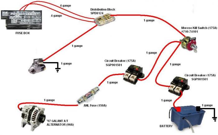
This diagram can give you the idea of wiring without a remote soleinoid.
-
Senior Member
Thanks ACB...exactly what I needed to see! Now I just need to find a good "accessible" location for the solenoid .
.
33' Hot Rod Coupe/Roadster (GEN 1), Fendered, Ford 302, 350hp, EFI, AOD, 4-Link, Double Adjustable Koni Coilovers, Split Rear Exhaust, Electric Power Steering, AC/Heat/Defrost, Moser 8.8"-3.55, Willwood Front/Rear Brakes, 18" x 8" Fronts/20" x 10" Rears, Ordered: 1.26.17, Arrived: 3.29.17, First Start: 7.2.18, Go Cart: 11.4.18 Paint/Body: 2.23.19, Back Home: 11.24.19, Completed: NEVER!; View More Pics @
https://starmobileone.com/
-
Seasoned Citizen

I know folks will sometimes run a Ford style remote solenoid as an easy fix to a hot start problem. When the integral mounted solenoid coil gets heat soaked from the exhaust manifold the coil resistance goes up and the solenoid may not pull in reliably. The first schematic posted by AC Bill shows what appears to be a high current style remote solenoid being used like a common relay to operate the coil of the integral starter solenoid.
So JOP33 why do you think you're going to need two solenoids to operate the starter on your hot rod? Yes you stated that the engine builder recommends it but did he say why? The starter coils don't typically draw enough current to require a relay between them and the starter switch but if you think it may it's a simple test with an ohm meter to determine the expected current draw. Measure the resistance of the coil in ohms and divide that number into 12 (12 volts) to get the current requirement (amps) of the starter solenoid coil. It's hard to believe it would be greater than the FFR starter switch provided in the kit. I'm just not convinced running a remote solenoid is necessary and especially wired as the first schematic above shows. If you need to supply more current to the starter solenoid then a garden variety automotive relay should be sufficient rather than a huge remote solenoid. But maybe I'm wrong.
Last edited by NAZ; 12-08-2017 at 10:50 AM.
-
The picture posted seems overly complicated, like someone's trying to sell a lot of unnecessary products. Never heard of using a fuse and a circuit breaker on the alternator wire. The wire routed from the distribution block to the fuse box is not protected. My fuse box came with a fusible link to protect the main feed wire.
-
FWIW....My motor has a mini starter with its own solenoid so I didn't see the necessity for adding another. With the exception of the two circuit breakers, my wiring scheme looks exactly like AC Bill's. I located the master disconnect switch on a panel in the center dash support, the distribution block and the ANL fuse for the alternator on the firewall behind the dash. Edwardb has some great pictures of this set up in his anniversary build thread.
 Posting Permissions
- You may not post new threads
- You may not post replies
- You may not post attachments
- You may not edit your posts
-
Forum Rules

Visit our community sponsor


 Reply With Quote