Looking for a cleaner way to run the starter and main power leads
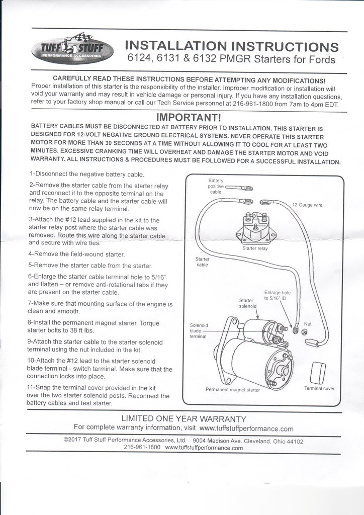
Right now, I have the battery and all the main power leads connected directly to my starter. The wires all reach, but I'm not thrilled with the way things look. I've mounted a binding post and I'm trying to figure out how best to connect everything. I assume I would want to connect the battery cable directly to the starter, but what size and type of connection should I use for the rest? What should I do for the starter wire (blue wire in the RF harness). My starter came with the following instructions, but I don't have a separate starter relay. Should I be using one?
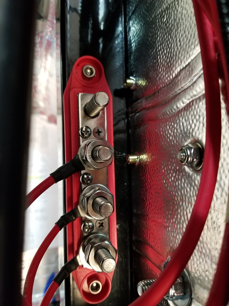
I too didn't like the idea or look of connecting all those wires at the starter. I followed Edwardb's lead on this one somewhat by using a master disconnect switch (MDS) in the cockpit and eliminating the extra solenoid that the directions call for. My battery location is in the trunk in a dropped box. That is a long way from the starter so I changed out the main cable from the battery to the MDS to 2 gauge wire. From the MDS to the starter, a short run for me, I used the provided 4 gauge wire. I connected the main panel power wire to the hot side of the MDS. I used a buss bar mounted near the steering shaft to make all of the connections behind the dash. I also wired in a relay for the smaller, ignition starter wire so that high current does not pass through the switch. Finally, just like Edwardb, I put a large 100 amp fuse in series with the alternator cable. There are some pictures in my build thread that might better explain all of this. If you want more information, let me know.
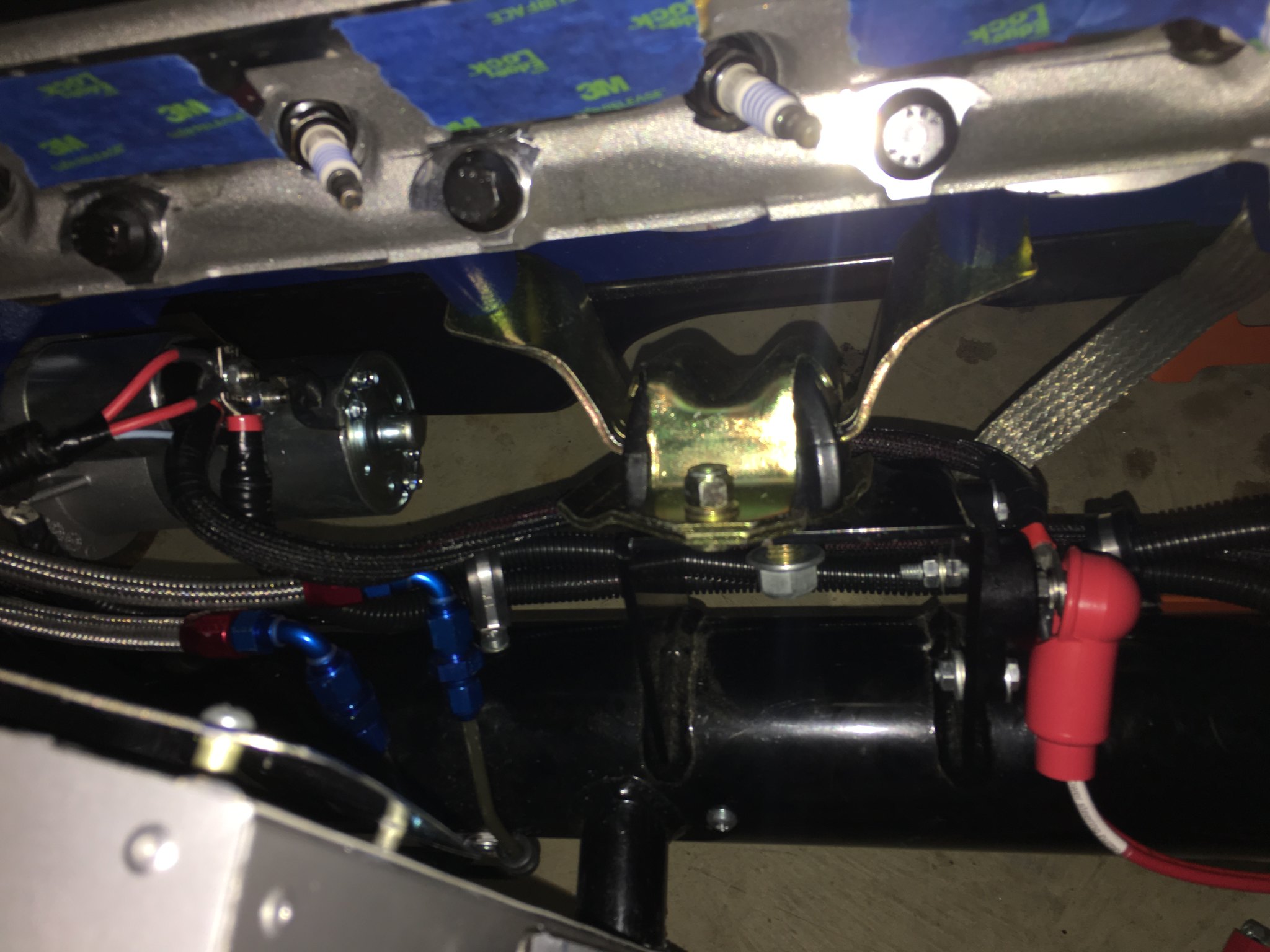
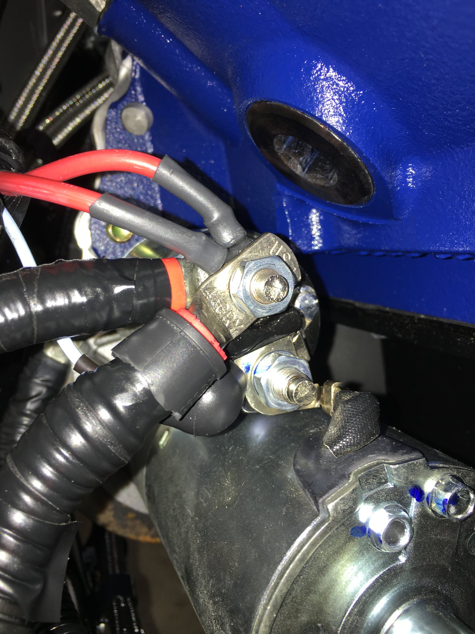
When I mocked up the power wiring on my build, I quickly determined there was no way to get all the power wires onto the starter solenoid, so I purchased a power post from Blue Sea systems (https://www.amazon.com/gp/product/B0...?ie=UTF8&psc=1) and mounted it to the right side engine mount. I considered running my battery to the power post and then have a single jumper to the starter solenoid, but that just seemed like a bad idea. So I ran the battery cable to the starter and then a jumper (4AWG) to the post. To get away from the header, I had to run the jumper around the back of the motor mount.
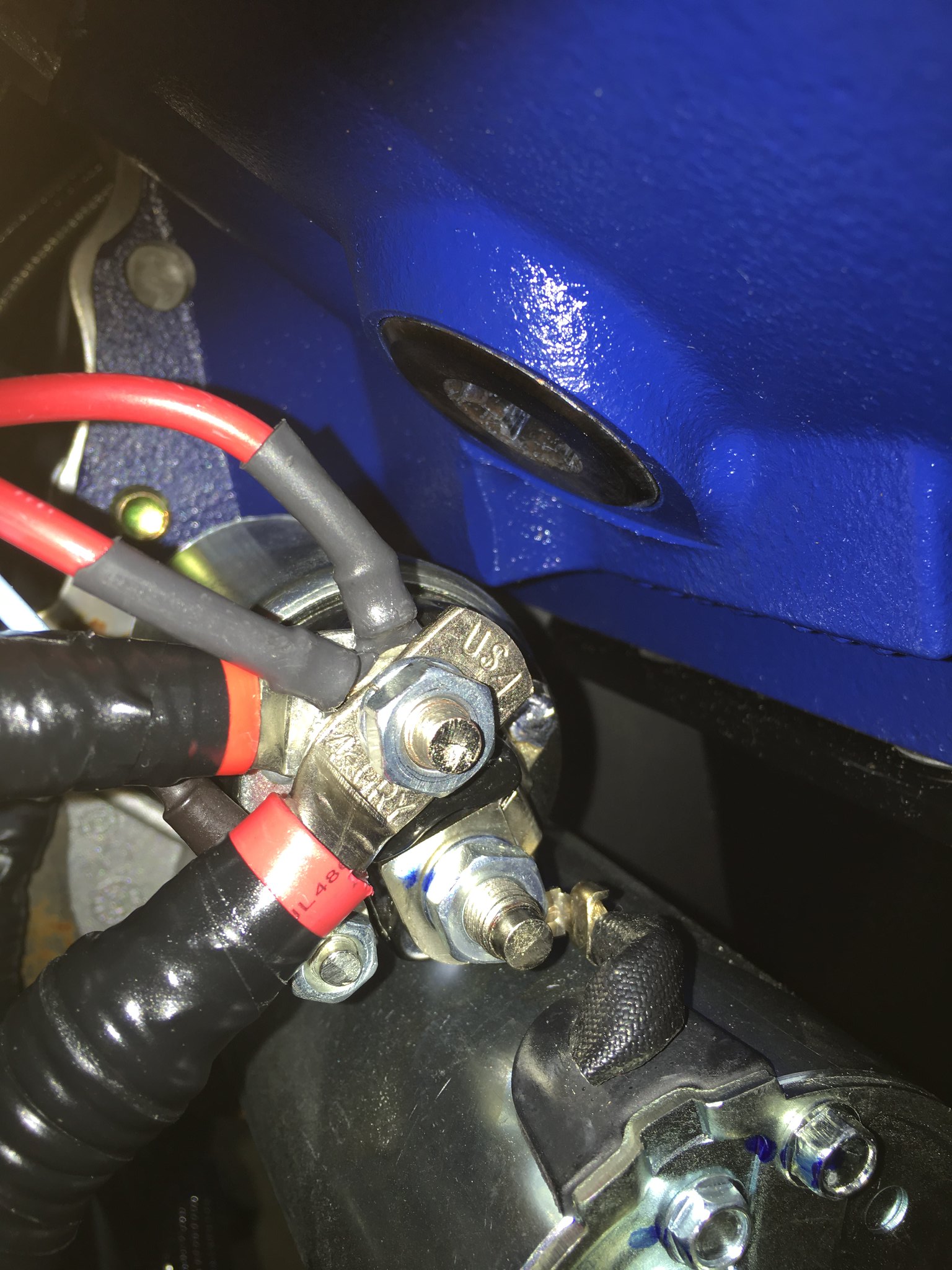
Note the positive battery cable (on top, at 8 o'clock) runs directly across the top of the solenoid wire. The insulation could actually touch the solenoid wire if I let the cable droop downwards. If I flipped the cable over so that it’s at four o’clock, then the cable touched the negative terminal on the solenoid.
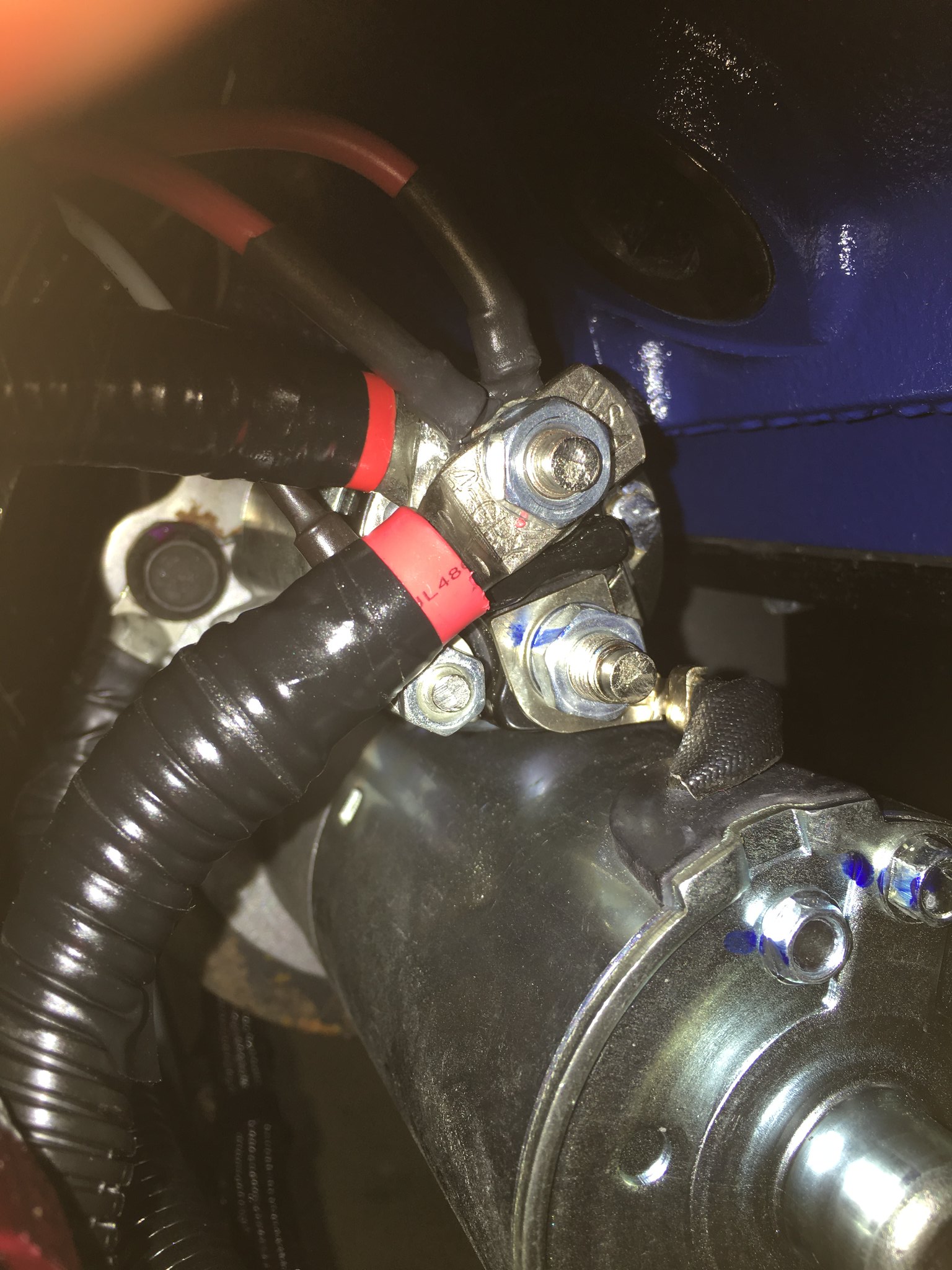
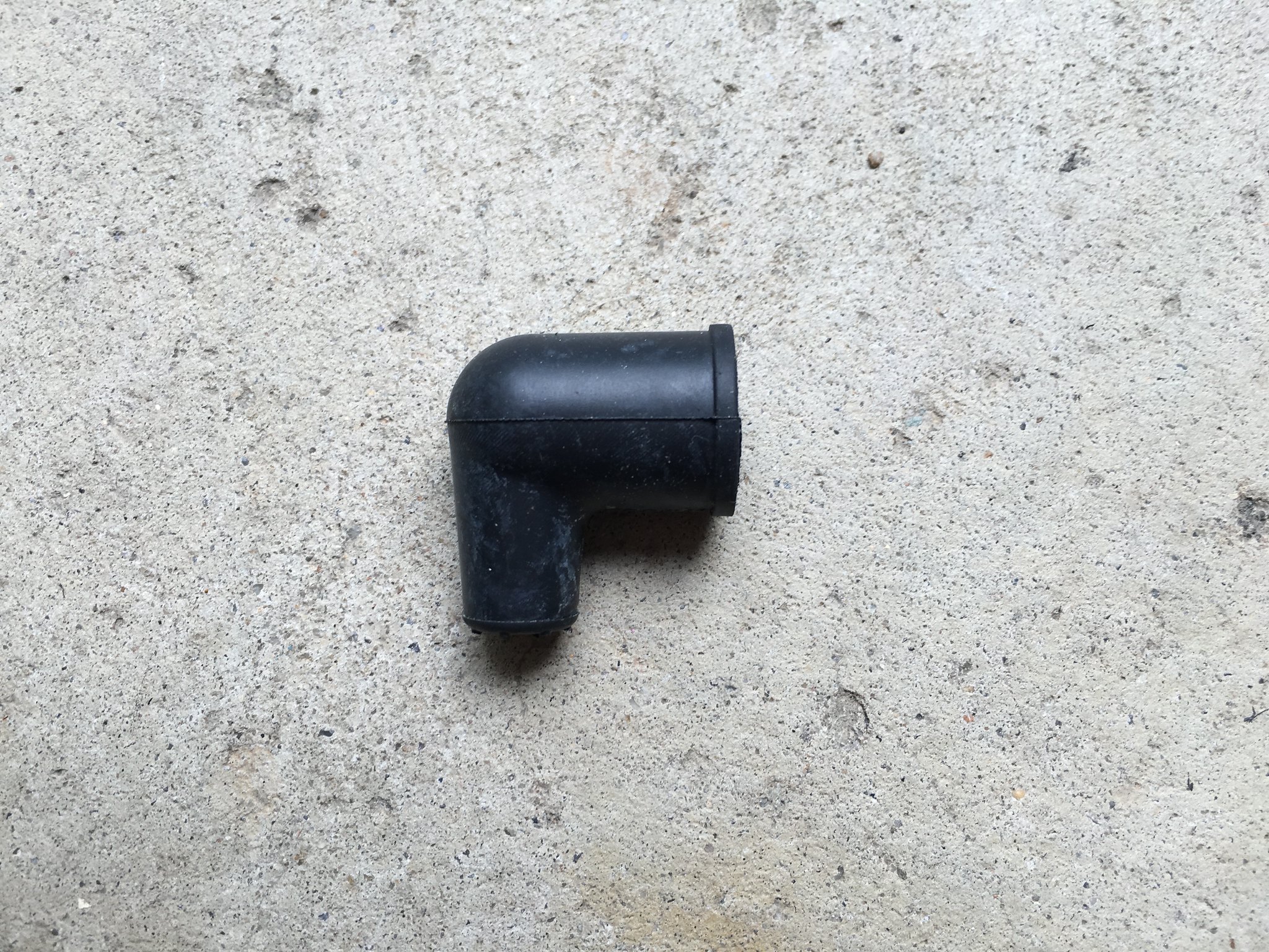
To minimize the chance of a runaway starter, I doubled up on the insulation. I purchased an alternator output boot (73 cents at NAPA), cut the large insulation ring off the post side, and slid the boot onto the solenoid wire and post.
Dave, I reread what I wrote to you this morning and realized it is not very clear. Not enough coffee I guess. The following is a hand drawn schematic showing how I rerouted all those wires they wanted to attach to the starter solenoid. I've included a couple of pictures of the installation as well. Joel
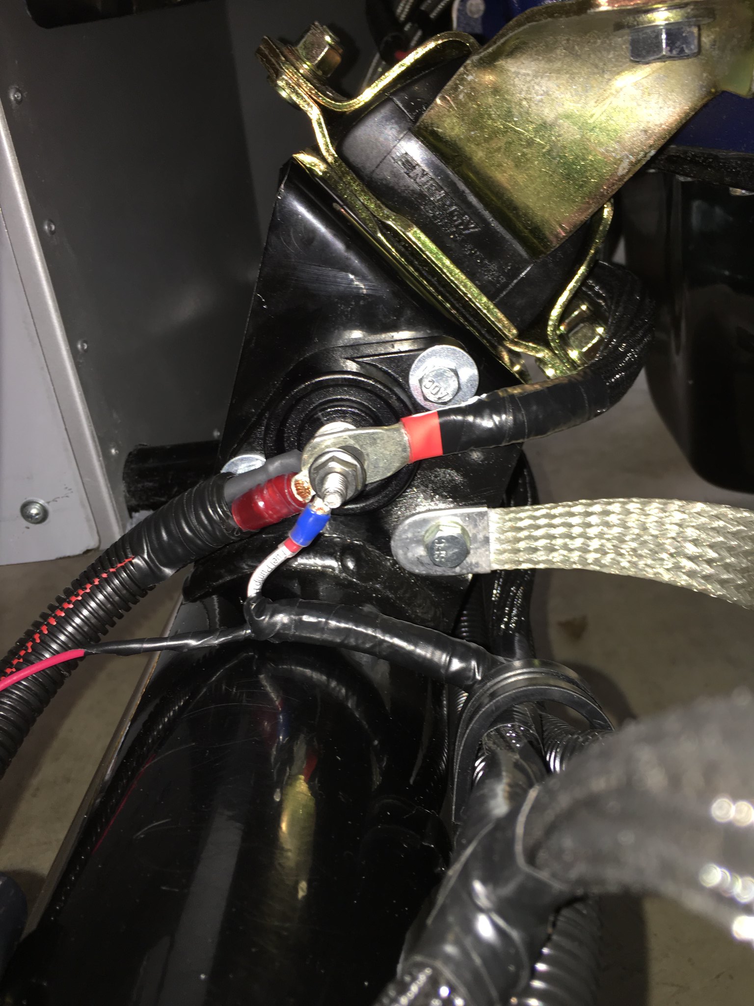
The three wires that are in the Ron Francis (RF) harness that would have attached at the starter solenoid are all red. I pulled them out of the harness tube and routed them inside the firewall, behind the dash. The fourth wire is the #16 AWG blue wire that would have gone to the small terminal on the starter. I cut this wire in the harness behind the dash and installed a relay then ran a new blue wire from the relay to the starter solenoid.
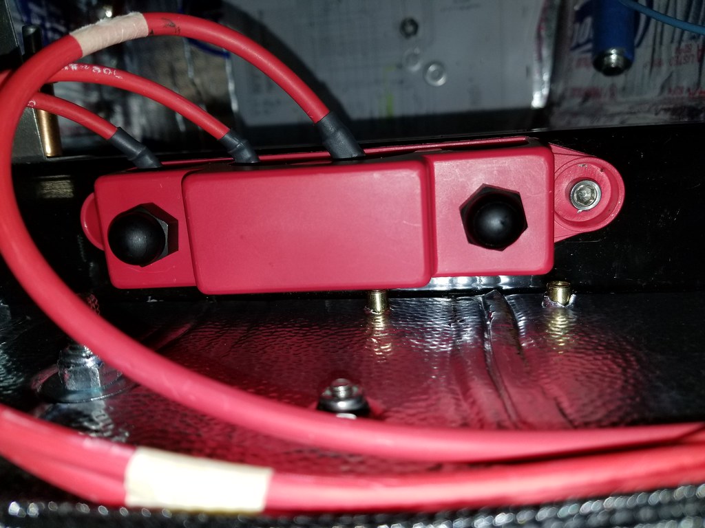
This is a shot of the master disconnect switch which in my car mounts in a panel on the center dash support panel. You can't see much of the wiring here but can get a sense of where it's located. Whenever possible, I ran the wires in the original RF harness tubes. In this picture you can also see the inline fuse for the alternator (covered).
Good work and thanks for sharing. Great timing as I am doing precisely this work on my build. The only thing I don't have is the relay. Can you share the wiring for it? Greatly appreciated.
Dave, I reread what I wrote to you this morning and realized it is not very clear. Not enough coffee I guess. The following is a hand drawn schematic showing how I rerouted all those wires they wanted to attach to the starter solenoid. I've included a couple of pictures of the installation as well. Joel
The three wires that are in the Ron Francis (RF) harness that would have attached at the starter solenoid are all red. I pulled them out of the harness tube and routed them inside the firewall, behind the dash. The fourth wire is the #16 AWG blue wire that would have gone to the small terminal on the starter. I cut this wire in the harness behind the dash and installed a relay then ran a new blue wire from the relay to the starter solenoid.
This is a shot of the master disconnect switch which in my car mounts in a panel on the center dash support panel. You can't see much of the wiring here but can get a sense of where it's located. Whenever possible, I ran the wires in the original RF harness tubes. In this picture you can also see the inline fuse for the alternator (covered).
Thank you for the added details. I have a bus bar already and other than the master switch, I think I'll be setting mine up following your design. For the relay I assume the existing starter (blue) wire to pin 86, pin 30 to the bus bar, pin 85 to ground, and pin 87 to the starter?
Here is a hand drawn schematic for the starter relay. I stole it from Edwardb. This will avoid high current running through the ignition switch. Pick up the existing blue wire from the harness and attach to pin 86 on the relay. Get 12V power somewhere. I got it from my buss bar but it could come from other places. Attach the 12V power to terminal 30. Run another blue wire from pin 87 on the relay to the small terminal on the starter solenoid. Pin 85 is the ground. I grounded mine to the chassis behind the dash. Pin 87a is not used.
As an alternative to the short stud at the back of most starters, and for those of you who absolutely need to tie ALL you wires to it, Try using a threaded coupler as the "nut" that holds the battery/starter cable to the starter. Then the other end becomes free to handle a few more smaller with the simple use of a short bolt to hold it all together.
Just my 2¢
Doc
FFR3712K (MKII) in Lost Wages Nevada.
5.0 w/tubular GT-40 EFI, E303 cam, Custom 4 into 4 headers, T5, 3-Link 3.73 rear. Full F5 tubular suspension. Drop Butt mod, Dash forward mod, custom foot box air vents, custom turn signal system. 13" PBR brakes, Fiero E-Brake mod, Flaming River 18:1 rack w/ F5 bump steer kit on Breeze bushings. 17" Chrome Cobra "R's" w/ 275 fronts and 315 rears. MKIV seats. FORD Royal Blue w/ Arctic White stripes.
I prefer to have just one battery cable on the starter. At some point you may need to remove it and it's in a very awkward location. The more wires, the more of a pain it is. If using the firewall solenoid like Papa shows, the battery+ stud can be your power source for everything else. If not the power post that Phileas uses is nice as it has a good long stud. If you need extra power sources the bus bar works well too. Note though, that there is no fuse in either of these, so be careful how the wires are routed and insulated
FFR MkII, 408W, Tremec TKO 500, 2015 IRS, DA QA1s, Forte front bar, APE hardtop.
Here is a hand drawn schematic for the starter relay. I stole it from Edwardb. This will avoid high current running through the ignition switch. Pick up the existing blue wire from the harness and attach to pin 86 on the relay. Get 12V power somewhere. I got it from my buss bar but it could come from other places. Attach the 12V power to terminal 30. Run another blue wire from pin 87 on the relay to the small terminal on the starter solenoid. Pin 85 is the ground. I grounded mine to the chassis behind the dash. Pin 87a is not used.
Why can't the blue wire be connected directly to the starter solenoid small terminal without going through the firewall bus bar. That way the relay is not necessary. Am I missing something here? Strong proponent of the KISS principle!
You can send the wire directly to the starter as you suggest. There is no problem with that and it is certainly the most simple application and the one that is describe in the instructions and probably the one that most do. The chances are you will never have a problem doing it that way. When done like that, it runs all of the high current when starting the motor through the ignition switch. Most ignition switches are not designed to handle that sort of current day in and day out. Using a relay in the circuit simply avoids having the high current run through the ignition switch. Many will debate the necessity of doing this, and I am not arguing for it one way or the other. It is how I did it mostly because I had this issue of burning up ignition switches on my Detomaso Pantera and just figured I would avoid the potential of that problem. It's a simple solution for that issue but, again, probably not important to everyone.
As an alternative to the short stud at the back of most starters, and for those of you who absolutely need to tie ALL you wires to it, Try using a threaded coupler as the "nut" that holds the battery/starter cable to the starter. Then the other end becomes free to handle a few more smaller with the simple use of a short bolt to hold it all together.
I also ordered a bulkhead pass-through terminal to bring the main power in, but that won't be here for a few more days. I'll get the relay wired up for the ignition next.
Lots of cheaper options out there, too. You don't need a double throw relay for this application, but it doesn't hurt; just don't connect 87a, which is normally closed (NC).


 Thanks:
  Likes:


 Reply With Quote