Very Cool Parts

Visit our community sponsor

Thanks Thanks:  0
Likes Likes:  0
Results 1 to 23 of 23

Thread: Mk IV Gauge Wiring

  1. #1
    Senior Member
    Join Date
    Mar 2011
    Location
    Heart of Dixie, Alabama
    Posts
    1,854
    Post Thanks / Like

    Mk IV Gauge Wiring

    I am trying to get back to work on my Mk IV Anniversary after a long winter of down time.
    I want to start wiring my dash and instruments. Any tips on cutting off and or mating of the gauges wires to the harness. I was thinking of putting the lighting on a plug to the harness, same with the gauge inputs. I can see where solder and heat shrink will be good in places, but think splices, plugs and wiring extensions will be needed. Any quick tips, connectors or links to build threads will be appreciated.
    20th Anniversary Mk IV, A50XS Coyote, TKO 600, Trunk Drop Box, Trunk Battery Box, Cubby Hole, Seat Heaters, Radiator hanger and shroud.

  2. #2
    Senior Member Itchief's Avatar
    Join Date
    Aug 2017
    Location
    Southern WV
    Posts
    376
    Post Thanks / Like
    I used plugs/connectors everywhere possible for gauges lights fan etc so that it would be easier to disconnect for testing and repair

    I like to do a lineman splice with soldier and heat shrink when splicing wires

    Good luck

    Rick
    #8475 Complete Kit Delivered Nov 2014, started Nov 2015, Street Legal Apr 2016, Paint and Interior Completed Aug 2017, 390 BBF, March accessory kit, MSD Atomic EFI and Ready to run, TKO 500 with MidShift kit, hooker headers, 3 link, track lock with 3.55, sway bars, power steering, wipers, heater

  3. #3
    Senior Member CDXXVII's Avatar
    Join Date
    Feb 2011
    Location
    Santa Clarita, CA.
    Posts
    757
    Post Thanks / Like
    I made my own dash harness and mated it to the Ron Francis harness.

    D98280D2-2307-49D0-A448-40F4FFF2554C.jpeg

  4. #4
    Senior Member phileas_fogg's Avatar
    Join Date
    Jun 2015
    Location
    Fairfax Station VA
    Posts
    1,235
    Post Thanks / Like
    My wiring is a mess, but everything works. I made sure I could remove and replace any instrument, switch, or bulb without removing the dash. I used a combination of gauge connectors, weatherpak connectors, and bullet connectors. My build log http://www.ffcars.com/forums/17-fact...r-build-3.html has details starting at post #304. Don't worry about the re-bundling of wires I did; that was to accommodate the competition layout for my dash and is unnecessary for the standard layout.

    Cheers,


    John
    MK IV Roadster #8631
    Ford 302, Holley Terminator EFI, T5z, 3.55 Rear End, IRS, 17” Halibrand Replicas (9” front, 10.5” rear), Nitto 555 G2’s (275/40ZR17 front, 315/35ZR17 rear), Fast Freddie’s Power Steering, F5 Wilwood Brakes, FFMetal’s Firewall Forward, Forte’s Hydraulic Clutch & Throttle Linkage
    https://www.ffcars.com/threads/phile.../#post-4776313

  5. #5
    On a roll Al_C's Avatar
    Join Date
    Aug 2014
    Location
    Wheaton, IL
    Posts
    1,414
    Post Thanks / Like
    Railroad - which gauges are you using? If the vintage variety, we have a good thread going here: https://thefactoryfiveforum.com/show...e-Gauge-Wiring It helped me a lot. Hope this helps!
    Mk IV Roadster - #8650 - delivered 7-17-2015 - first start 7-28-2018 - first go-kart 10-13-2018 - licensed and on the road 9-9-19: body/paint completed 3-17-2020.
    Complete kit / 2015 Coyote / TKO600 / IRS / Wilwood brakes / Mid-Shift mod / Power Steering / Heater and Seat Heaters / RT turn signal / Breeze radiator shroud and mount

  6. #6
    Senior Member
    Join Date
    Mar 2011
    Location
    Heart of Dixie, Alabama
    Posts
    1,854
    Post Thanks / Like
    Thanks for all the tips, replys and links. I will sit down tonight and follow the leads.
    My gauges are the Speedhut, I think. I do not know if they are the vintage. I think they have lighted needles and background lighting. They are included with the anniversary package.
    I will try to get my bearings on what is what later. I have to get some gypsum on the yard, before the next rain. Thanks,
    20th Anniversary Mk IV, A50XS Coyote, TKO 600, Trunk Drop Box, Trunk Battery Box, Cubby Hole, Seat Heaters, Radiator hanger and shroud.

  7. #7
    Senior Member edwardb's Avatar
    Join Date
    Feb 2011
    Location
    Lake Orion, Michigan
    Posts
    10,575
    Post Thanks / Like
    Quote Originally Posted by Railroad View Post
    Thanks for all the tips, replys and links. I will sit down tonight and follow the leads.
    My gauges are the Speedhut, I think. I do not know if they are the vintage. I think they have lighted needles and background lighting. They are included with the anniversary package.
    I will try to get my bearings on what is what later. I have to get some gypsum on the yard, before the next rain. Thanks,
    The 20th Anniversary gauges are Speedhut. The links with the instructions included should get you going. The one minor gotcha is that Ron Francis did release a newer version of the wiring harness since the 20th Anniversary models were sold. The newer version is more plug and play. But the older one is still pretty straightforward. Read through the links and let us know if there are still questions.
    Build 1: Mk3 Roadster #5125. Sold 11/08/2014. Build 2: Mk4 Roadster #7750. Sold 04/10/2017. Build Thread
    Build 3: Mk4 Roadster 20th Anniversary #8674. Sold 09/07/2020. Build Thread and Video. Build 4: Gen 3 Type 65 Coupe #59. Gen 3 Coyote. Legal 03/04/2020. Build Thread and Video
    Build 5: 35 Hot Rod Truck #138. LS3 and 4L65E auto. Rcvd 01/05/2021. Legal 04/20/2023. Build Thread. Sold 11/9/2023.

  8. #8
    Senior Member
    Join Date
    Mar 2011
    Location
    Heart of Dixie, Alabama
    Posts
    1,854
    Post Thanks / Like
    Thanks edwardb, I hope to buy some wire, connectors, etc this week and tackle this. I bought my MkIV Anniversary at the end of 2016, so I will have to check which Ron Francis harness I might have.
    20th Anniversary Mk IV, A50XS Coyote, TKO 600, Trunk Drop Box, Trunk Battery Box, Cubby Hole, Seat Heaters, Radiator hanger and shroud.

  9. #9
    Senior Member
    Join Date
    Mar 2011
    Location
    Heart of Dixie, Alabama
    Posts
    1,854
    Post Thanks / Like
    Quote Originally Posted by CDXXVII View Post
    I made my own dash harness and mated it to the Ron Francis harness.

    D98280D2-2307-49D0-A448-40F4FFF2554C.jpeg
    That wiring looks really good. Hopefully, I can do something close.
    20th Anniversary Mk IV, A50XS Coyote, TKO 600, Trunk Drop Box, Trunk Battery Box, Cubby Hole, Seat Heaters, Radiator hanger and shroud.

  10. #10
    Senior Member edwardb's Avatar
    Join Date
    Feb 2011
    Location
    Lake Orion, Michigan
    Posts
    10,575
    Post Thanks / Like
    Quote Originally Posted by Railroad View Post
    Thanks edwardb, I hope to buy some wire, connectors, etc this week and tackle this. I bought my MkIV Anniversary at the end of 2016, so I will have to check which Ron Francis harness I might have.
    The Ron Francis chassis wiring harness instructions that came with my 20th Anniversary Roadster in 2015 were marked Revision N, September 2014. My Coupe (same harness is used on the Coupe, Hot Rod and Roadster) delivered late last year came with Revision S, February 2017. I had heard about the newer harness. I didn't review every single detail, but one of the obvious differences is the dash harness. It comes set up for the Vintage gauges, which are also now mentioned in the instructions. If you received this newer harness, your work should be a little simpler. If you didn't, still no big deal IMO. Lots of threads have described how to connect the Vintage gauges to the RF harness. Regardless of which version harness you have, if you use the provided RF dash harness and Speedhut supplied dash chains, it's really not necessary to buy additional wire or connectors. Everything you need is there. Unless you want to go some other direction.
    Last edited by edwardb; 03-05-2018 at 06:55 AM.
    Build 1: Mk3 Roadster #5125. Sold 11/08/2014. Build 2: Mk4 Roadster #7750. Sold 04/10/2017. Build Thread
    Build 3: Mk4 Roadster 20th Anniversary #8674. Sold 09/07/2020. Build Thread and Video. Build 4: Gen 3 Type 65 Coupe #59. Gen 3 Coyote. Legal 03/04/2020. Build Thread and Video
    Build 5: 35 Hot Rod Truck #138. LS3 and 4L65E auto. Rcvd 01/05/2021. Legal 04/20/2023. Build Thread. Sold 11/9/2023.

  11. #11
    Senior Member
    Join Date
    Mar 2011
    Location
    Heart of Dixie, Alabama
    Posts
    1,854
    Post Thanks / Like
    Edwardb, thanks for the detailed guidance. Obviously, I need to do some more digging into my specific harness and parts.
    20th Anniversary Mk IV, A50XS Coyote, TKO 600, Trunk Drop Box, Trunk Battery Box, Cubby Hole, Seat Heaters, Radiator hanger and shroud.

  12. #12
    Senior Member
    Join Date
    Mar 2011
    Location
    Heart of Dixie, Alabama
    Posts
    1,854
    Post Thanks / Like
    Not in the dash wiring, but need some guidance on the alt wiring. I have a gen 1 coyote engine and wiring harness. My alternator came with the engine, A50XS. My Ron Francis has 2 large red wires, probably 10 ga with a 2 prong connector. The second alt wire has 2 small wires, 14 ga, red and brown, also on a connector. My alternator has one large threaded post and one female weathertite connection. The engine harness has a wire for the weathertite connector. I need info on how to connect the 2 large red and smaller red and brown wires. The brown wire seems to run back to the acc post on the ign switch. I could not trace the red wire in the same loom and connector.

    Next question, the engine has a wiring harness that runs down to the alt area. The loom has a heat shield on it. The loom has one weathertite connector with a green and a green with white tracer wire in it.
    The second wire is gray? or off white, single wire with connector. These wires may have been for the low oil sensor and/or the sensors that got replaced. What do I do with these wires? My pan did not have the low oil sensor, so I could not match the connectors.

    Thanks big time, in advance.
    20th Anniversary Mk IV, A50XS Coyote, TKO 600, Trunk Drop Box, Trunk Battery Box, Cubby Hole, Seat Heaters, Radiator hanger and shroud.

  13. #13
    Senior Member edwardb's Avatar
    Join Date
    Feb 2011
    Location
    Lake Orion, Michigan
    Posts
    10,575
    Post Thanks / Like
    For the alternator, you only need one single large gauge connection from the RF harness to the threaded post. If you strip back the tape and loom on the end of the RF alternator leg, you'll see all but the brown wires come together just a little ways up. Shows that in the schematic as well. Just cut the extra wires and connectors off, add a ring terminal to the single wire remaining, and attach to the Coyote alternator. That brown wire is also not needed. You could just cap it there (do a good job, it's a live wire) or trace it all the way back to the ignition switch and remove. As you already said, the alternator connector from the Coyote harness goes into the alternator socket.

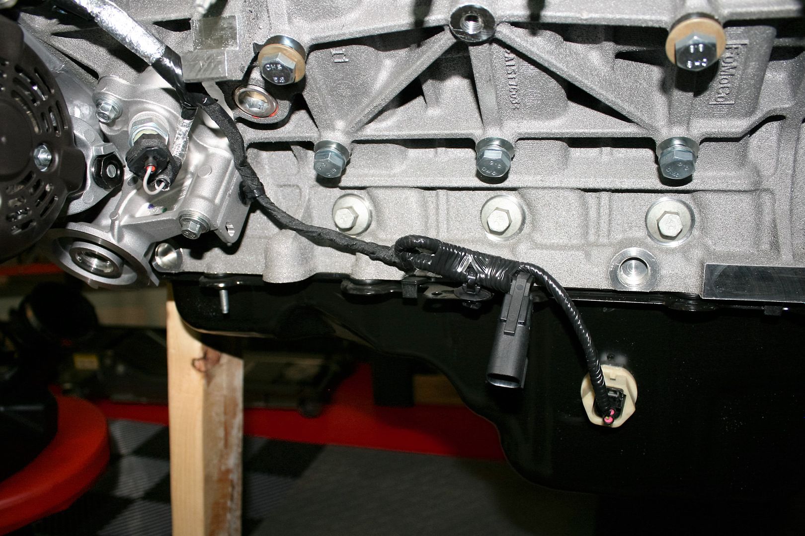
    For the other question, my Coyote is a Gen 2, so there are differences. But comparing to mine, sounds like the single wire is the oil pressure sensor. The sensor has to stay. The FF Coyote instructions show adding a T so you can have the Coyote sensor and also the additional sensor needed for the oil pressure gauge. The other one does sound like the low oil sensor. But the colors don't exactly match. Both are visible in this picture of mine. Ignore the other connector right in the middle. That's the DS O2 sensor connector. On the Gen 2 they moved it here as part of the engine harness. Yours is different.

    Last edited by edwardb; 03-09-2018 at 09:17 PM.
    Build 1: Mk3 Roadster #5125. Sold 11/08/2014. Build 2: Mk4 Roadster #7750. Sold 04/10/2017. Build Thread
    Build 3: Mk4 Roadster 20th Anniversary #8674. Sold 09/07/2020. Build Thread and Video. Build 4: Gen 3 Type 65 Coupe #59. Gen 3 Coyote. Legal 03/04/2020. Build Thread and Video
    Build 5: 35 Hot Rod Truck #138. LS3 and 4L65E auto. Rcvd 01/05/2021. Legal 04/20/2023. Build Thread. Sold 11/9/2023.

  14. #14
    Senior Member
    Join Date
    Mar 2011
    Location
    Heart of Dixie, Alabama
    Posts
    1,854
    Post Thanks / Like
    Thanks edwardb. I think I can get something done with your help. It has been a while since I did any work on the project and I could not put my hands on the original oil pressure sensor. I am in a bit of a quandary on the oil sensor. Does ECU need that information to function? I saw some pictures with and without the sensor. If I can locate the sensor, I will probably reinstall it on a Tee.
    I saw the schematic on the alt wires, but it did not register about them branching off a single leg. Thanks for the clarification.
    While your helping me, can you identify a bag of parts?? the number is 12455 and contains a toggle switch, relay, length of blue wire and some mounting screws.
    Thanks for bailing me out.
    20th Anniversary Mk IV, A50XS Coyote, TKO 600, Trunk Drop Box, Trunk Battery Box, Cubby Hole, Seat Heaters, Radiator hanger and shroud.

  15. #15
    Senior Member edwardb's Avatar
    Join Date
    Feb 2011
    Location
    Lake Orion, Michigan
    Posts
    10,575
    Post Thanks / Like
    Quote Originally Posted by Railroad View Post
    Thanks edwardb. I think I can get something done with your help. It has been a while since I did any work on the project and I could not put my hands on the original oil pressure sensor. I am in a bit of a quandary on the oil sensor. Does ECU need that information to function? I saw some pictures with and without the sensor. If I can locate the sensor, I will probably reinstall it on a Tee.
    I saw the schematic on the alt wires, but it did not register about them branching off a single leg. Thanks for the clarification.
    While your helping me, can you identify a bag of parts?? the number is 12455 and contains a toggle switch, relay, length of blue wire and some mounting screws.
    Thanks for bailing me out.
    I just responded on another thread. Looking at the most recent instructions on the FF website, it does say remove the OE Coyote oil pressure sender and replace with the Speedhut one. That's different than what it said when I did mine with a tee connection, leaving the OE one and adding the Speedhut sender, and how I responded when you asked the question. Also a bit confusing as you say because the tee connection is still pictured in the FF instructions. I suspect it's just fine without it. Apparently the OE sender is also only for the gauge display, and not needed since the Speedhut sender is all that's needed for gauges in our builds. FWIW, I just looked at the data log files used by the tuner on my Coyote. Of the nearly 40 data streams coming out of the computer, oil pressure isn't one of them. Apparently the computer doesn't monitor it either, which supports not needing the OE sender.

    Part number 12455 is cooling fan relay parts. You don't need them. The simplest method is to have the Coyote cooling fan wire directly to the cooling fan. The Coyote PDB and PCM will control and power it.
    Build 1: Mk3 Roadster #5125. Sold 11/08/2014. Build 2: Mk4 Roadster #7750. Sold 04/10/2017. Build Thread
    Build 3: Mk4 Roadster 20th Anniversary #8674. Sold 09/07/2020. Build Thread and Video. Build 4: Gen 3 Type 65 Coupe #59. Gen 3 Coyote. Legal 03/04/2020. Build Thread and Video
    Build 5: 35 Hot Rod Truck #138. LS3 and 4L65E auto. Rcvd 01/05/2021. Legal 04/20/2023. Build Thread. Sold 11/9/2023.

  16. #16
    Senior Member
    Join Date
    Mar 2011
    Location
    Heart of Dixie, Alabama
    Posts
    1,854
    Post Thanks / Like
    Edwardb, thanks for following up with that information. I will be able to complete that side of the engine and move on. I hope to go cart this year.
    20th Anniversary Mk IV, A50XS Coyote, TKO 600, Trunk Drop Box, Trunk Battery Box, Cubby Hole, Seat Heaters, Radiator hanger and shroud.

  17. #17
    Senior Member
    Join Date
    Mar 2011
    Location
    Heart of Dixie, Alabama
    Posts
    1,854
    Post Thanks / Like
    I am baaack. I am ready to add the speed dial, M-4209ADAPT-A to my Gen 1 Coyote eng and M-6017-A504VA wiring harness. I have the Speedhut GPS fed speedometer and TKO-600 trans.
    I am referring to REV T of the Roadster Coyote Installation pdf.

    It looks like I do not have to disassemble the ECU plug, just solder and insulate the wires, that come out of the Speed Dial and the ECU harness.
    In addition to confirmation of this, I could use some tutoring on the procedure. I will not go into more detail, as if you have done this, it makes sense.
    The more detail the better, I feel dense on some of this.
    As always, thanks for any help.
    Last edited by Railroad; 03-16-2018 at 01:43 PM.
    20th Anniversary Mk IV, A50XS Coyote, TKO 600, Trunk Drop Box, Trunk Battery Box, Cubby Hole, Seat Heaters, Radiator hanger and shroud.

  18. #18
    Senior Member edwardb's Avatar
    Join Date
    Feb 2011
    Location
    Lake Orion, Michigan
    Posts
    10,575
    Post Thanks / Like
    Good luck. I have no experience with the Gen 1 Coyote, so can't provide any specific pointers. Lots of guys installed them though, so hopefully you'll find what help you need. The one thing I would add though is that my understanding is later versions of the Gen 1 Ford Performance harness had connections pre-installed for the speed dial so you didn't have to break into the ECU plug. Something to check.
    Build 1: Mk3 Roadster #5125. Sold 11/08/2014. Build 2: Mk4 Roadster #7750. Sold 04/10/2017. Build Thread
    Build 3: Mk4 Roadster 20th Anniversary #8674. Sold 09/07/2020. Build Thread and Video. Build 4: Gen 3 Type 65 Coupe #59. Gen 3 Coyote. Legal 03/04/2020. Build Thread and Video
    Build 5: 35 Hot Rod Truck #138. LS3 and 4L65E auto. Rcvd 01/05/2021. Legal 04/20/2023. Build Thread. Sold 11/9/2023.

  19. #19
    Senior Member
    Join Date
    Mar 2011
    Location
    Heart of Dixie, Alabama
    Posts
    1,854
    Post Thanks / Like
    With some good help, we got the speed dial wired in today, all of the dash lighting and other misc from the Ford and RF harness. We wired the Speed Hut gauge needles to light up with key on and back lighting through the headlight switch dimmer control. We put 12 volts on everything to confirm the wiring and function. I have the RT VW steering column and have to wire in the turn signal, 4 ways, horn and hd light dimmer. I think I want the hd light dimmer on the turn signal lever button, with the horn on a button the the dash. Any advise, whether this is good or bad, is welcome. Naturally, I am trying to locate them ergonomically convenient. Do I need to buy a relay for the headlights and or the horn.
    My electrical assistant recommended a DPDT latching relay for the head light dimmer and we are guessing 30 amp. Right or wrong?
    Also, need advise on the master disconnect switch. I think the vertical panel at the front of the console is a good location. I have circuits that need to stay hot all the time. I know this stuff is in the build threads and hope you guys do not mind replying, saving me some time.
    Last edited by Railroad; 03-22-2018 at 06:43 PM. Reason: add on
    20th Anniversary Mk IV, A50XS Coyote, TKO 600, Trunk Drop Box, Trunk Battery Box, Cubby Hole, Seat Heaters, Radiator hanger and shroud.

  20. #20
    Senior Member edwardb's Avatar
    Join Date
    Feb 2011
    Location
    Lake Orion, Michigan
    Posts
    10,575
    Post Thanks / Like
    Interesting wiring on the gauge lighting. Having the needles lit all the time is a cool touch I guess. Not sure how visible they will be in the daylight though. Normally those are just wired on the white gauge light wire along with the backlighting. But creativity isn't bad. You say the backlighting is through the headlight dimming circuit. I assume you mean the white gauge light wire, which does happen to go through the dimming circuit? But for the Speedhut gauges the headlight dimmer doesn't dim. It's basically just an on-off switch. Hopefully you installed the Speedhut provided inverter and adjustment knob. That's what gives dimming backlighting on those gauges.

    Putting the high/low beam on the RT turn signal stalk button is pretty common, along with a dash mounted button for the horn. I locate the horn button on the dash so it's under my right hand off the steering wheel. Your RF harness already has a relay for the horn. Just hook the horn(s) to the wires in the front harness, add a switch using the wires in the dash harness, and you're good to go. The headlights don't need a relay for regular operation using a dash mounted switch as shown in the RF schematic for low/high beam. In order to use the RT momentary switch for low/high beam you will need at least one relay though. Your RT unit should have come with a couple schematics that show how this can be wired.

    For the master disconnect, one way to have to have always on circuits is to wire them off the hot (unswitched) side of the switch. I wouldn't put too much there, otherwise it's no longer really a master disconnect, right? The main thing usually is the keep-alive for the EFI computer. Something like this is another common approach: https://www.breezeautomotive.com/det...hp?prod_id=284
    Last edited by edwardb; 03-23-2018 at 06:08 AM.
    Build 1: Mk3 Roadster #5125. Sold 11/08/2014. Build 2: Mk4 Roadster #7750. Sold 04/10/2017. Build Thread
    Build 3: Mk4 Roadster 20th Anniversary #8674. Sold 09/07/2020. Build Thread and Video. Build 4: Gen 3 Type 65 Coupe #59. Gen 3 Coyote. Legal 03/04/2020. Build Thread and Video
    Build 5: 35 Hot Rod Truck #138. LS3 and 4L65E auto. Rcvd 01/05/2021. Legal 04/20/2023. Build Thread. Sold 11/9/2023.

  21. #21
    Senior Member
    Join Date
    Mar 2011
    Location
    Heart of Dixie, Alabama
    Posts
    1,854
    Post Thanks / Like
    Edwardb, I was hoping you would help me with this.
    On the gauge lights, I thought I had read to turn the Speed Hut rheostat to bright and let the headlight switch dim/brighten the gauge lights. We put a meter on the headlight switch and it did regulate the resistance. We assumed this would be the dimming feature. Something I need clarification on, does the headlight switch feature a hi/low beam pull detent? I have that on my T Bucket, but did not read enough to know the answer, yet.

    On the horn and button, that location sounds right for me. Any advise on the best tools to use for drilling the pre covered plastic dash?,,, do not want something that will grab the covering and make a mess.
    I will review the RT schematics.

    Did you use a keyed master disconnect? I like the idea, I think. The fuse link for the KAM is great. I think I might look for a resetting circuit breaker, instead of the fuse. I can see blowing the fuse and not having one on hand.

    I will have to add your name to the builders list on my car. Thanks
    20th Anniversary Mk IV, A50XS Coyote, TKO 600, Trunk Drop Box, Trunk Battery Box, Cubby Hole, Seat Heaters, Radiator hanger and shroud.

  22. #22
    Senior Member Jdav's Avatar
    Join Date
    Sep 2016
    Location
    ATL GA
    Posts
    443
    Post Thanks / Like
    The FFR Upgraded Dash (the precoverd plastic one) already has a hole for the horn (unless you plan on using that for something else). But if you do still need to make a new hole, just use a new, sharp drill bit and tape the area you are drilling.
    MK4 #9028 - Coyote - TKO600
    Delivery: 1/30/17 First Start: 7/23/17 Legal: 10/5/17 Graduated: 10/15/18
    Build thread: http://thefactoryfiveforum.com/showt...8-Build-Thread

  23. #23
    Senior Member edwardb's Avatar
    Join Date
    Feb 2011
    Location
    Lake Orion, Michigan
    Posts
    10,575
    Post Thanks / Like
    Edwardb, I was hoping you would help me with this.

    On the gauge lights, I thought I had read to turn the Speed Hut rheostat to bright and let the headlight switch dim/brighten the gauge lights. We put a meter on the headlight switch and it did regulate the resistance. We assumed this would be the dimming feature.

    Nope, it’s the other way around. For the Speedhut gauges the dimming can only be accomplished with the provided inverter and adjustment knob. Turning the dimmer knob on the kit provided headlight switch varies voltage (not resistance) and as long as it’s above a certain voltage threshold, there’s enough to power the Speedhut circuit. Below that the Speedhut backlightling just shuts off. That’s why must recommend just keeping the headlight switch twisted to full on. You can find a more technical description of the Speedhut backlighting on their website. They’re AC powered electroluminescent panels. Hence the inverter.

    Something I need clarification on, does the headlight switch feature a hi/low beam pull detent? I have that on my T Bucket, but did not read enough to know the answer, yet.

    No. The kit provided headlight switch is an older GM Delco design that has two stops. First for running lights. Second for running lights plus headlights. In the second stop, 12V volts are output for the headlights. Via a switch (as shown in the RF schematic) or a relay, the 12V volts are applied either to the low or high beams of the headlight bulbs.

    On the horn and button, that location sounds right for me. Any advise on the best tools to use for drilling the pre covered plastic dash?,,, do not want something that will grab the covering and make a mess.

    Joel answered. Sounds OK to me. I don’t have any experience with that dash. Sorry.

    Did you use a keyed master disconnect? I like the idea, I think. The fuse link for the KAM is great. I think I might look for a resetting circuit breaker, instead of the fuse. I can see blowing the fuse and not having one on hand.

    I’ve not used a key master disconnect. I’ve not found them to be as heavy duty as others. I’m really not concerned about having another key. I consider it more of a safety item for long term storage and it’s useful when servicing to shut the whole car down.The keyed ignition switch is enough for me. I’ve used the Ron Francis MS1 on all my builds, and find it a decent quality switch that has held up well.

    I will have to add your name to the builders list on my car. Thanks

    You’re welcome. Happy to help. But you’re doing all the work.
    Build 1: Mk3 Roadster #5125. Sold 11/08/2014. Build 2: Mk4 Roadster #7750. Sold 04/10/2017. Build Thread
    Build 3: Mk4 Roadster 20th Anniversary #8674. Sold 09/07/2020. Build Thread and Video. Build 4: Gen 3 Type 65 Coupe #59. Gen 3 Coyote. Legal 03/04/2020. Build Thread and Video
    Build 5: 35 Hot Rod Truck #138. LS3 and 4L65E auto. Rcvd 01/05/2021. Legal 04/20/2023. Build Thread. Sold 11/9/2023.

Posting Permissions

  • You may not post new threads
  • You may not post replies
  • You may not post attachments
  • You may not edit your posts
  •  

Brown County Customs

Visit our community sponsor