Visit our community sponsor

Thanks:
0

Likes:
0
-
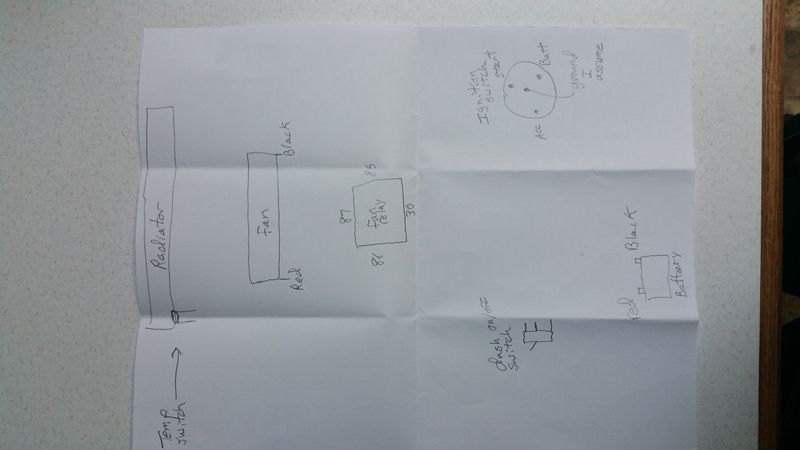
How to wire this diagram? Fan, relay, dash switch, temp switch, general ignition swi
Last edited by Tifford; 07-29-2018 at 05:46 PM.
Reason: Have not posted a pic in a while
-
-red battery cable to 30 on the relay(10 guage)
-87 on the relay to the red fan wire (10 guage)
-black wire on the fan to a ground on the frame
I am somewhat confused as to the rest.
1. From the relay what goes to the ignition switch batt terminal?
2. I assume the 3 post on/off lighted switch on the dash gets spliced into the temperature switch that's on the radiator? Right or wrong
3. What terminal on the relay 86 or 85 does the wire in question #2 go to?
Answers to these questions will help a lot.
-

OK. here's the low down. We really should have the fan ampacity before we start with relay, fuse and wire size but her goes.
Fan get grounded to your common ground point at the front of the car along with one side of the temp sensor (we're going to ground the relay to energize it).
Battery power to the fan runs in to terminal #30 on the relay.
Battery power out of the relay runs from terminal #87 of the relay to the positive side of the fan.
One side of the over-ride switch runs to ground.
Here is where it gets tricky. The second side of the temp sensor switch AND the second side of the over-ride switch run to terminal #86 of the relay. This way if either calls for the fan it turns on.
Switch power from the ignition switch runs to terminal # 85 of the relay, so as soon as the ignition switch is turned off the fan stops.
FWIW, you need to determine startup amperage of the fan and running load amps to determine the relay, fuse and wire size.
Last edited by i.e.427; 07-30-2018 at 12:29 PM.
-

Originally Posted by
i.e.427

OK. here's the low down. We really should have the fan ampacity before we start with relay, fuse and wire size but her goes.
Fan get grounded to your common ground point at the front of the car along with one side of the temp sensor (we're going to ground the relay to energize it).
Battery power to the fan runs in to terminal #30 on the relay.
Battery power out of the relay runs from terminal #87 of the relay to the positive side of the fan.
One side of the over-ride switch runs to ground.
Here is where it gets tricky. The second side of the temp sensor switch AND the second side of the over-ride switch run to terminal #86 of the relay. This way if either calls for the fan it turns on.
Switch power from the ignition switch runs to terminal # 85 of the relay, so as soon as the ignition switch is turned off the fan stops.
FWIW, you need to determine startup amperage of the fan and running load amps to determine the relay, fuse and wire size.
It works now. The on/off switch on the dash works. It's raining here now and I have to go to work in a short while but I'm fairly certain that the temp switch will work as well since they both go to 86 on the relay. It blows like a high performance leaf blower.
I did a bone head move on the wiring. I made two wires on the relay go to the same place. I felt stupid when I realized that.
In other news: On an huge box store on the Internet the question was asked as to how many amps this drew. The answer was 18. I have no clue as to the correctness of that answer. I do know that on start up that these fans draw more amps than a fan that has been running. On the box the recommended fuse value for this fan is 40. Currently I have a 30 which is not enough...but it's what I had to test it with. I promise the 30 will get switched out for something stronger.
A history of what happened. I had the original fan that came with the factory five kit which was a straight blade fan. It worked well for years. Then a plastic bag found its way onto one of the fins. Push came to shove and the 30 amp fuse melted. The metal in the fuse was fine but the plastic around the fuse melted. Never seen anything like it before. The plastic bag also caused the two factory wires going into the fan itself to melt. I would have figured that 30 fuse would have blown but it didn't. In researching this I have read somewhere that if a fan that binds up the amp draw can triple or even quadruple in a blink which I believe my old fan did.
In any case, it's on my bucket list to take this Factory Five Roadster that I mostly built myself (with its 492 horsepower Mike Forte engine) and circle these United States with it before I get to old to do so. It will be nice knowing that the fan will not be an issue.
Everything is not tucked away nice and neat yet. I'll leave the wires where they are for now and I'll put things back after I get a stronger relay.
Thank you for your time and knowledge.
 Posting Permissions
- You may not post new threads
- You may not post replies
- You may not post attachments
- You may not edit your posts
-
Forum Rules

Visit our community sponsor


 Thanks:
  Likes:


 Reply With Quote
