Very Cool Parts

Visit our community sponsor

Thanks Thanks:  0
Likes Likes:  0
Results 1 to 10 of 10

Thread: Tail light wiring question

  1. #1

    Join Date
    Apr 2017
    Location
    Elk Grove, NorCal
    Posts
    550
    Post Thanks / Like

    Tail light wiring question

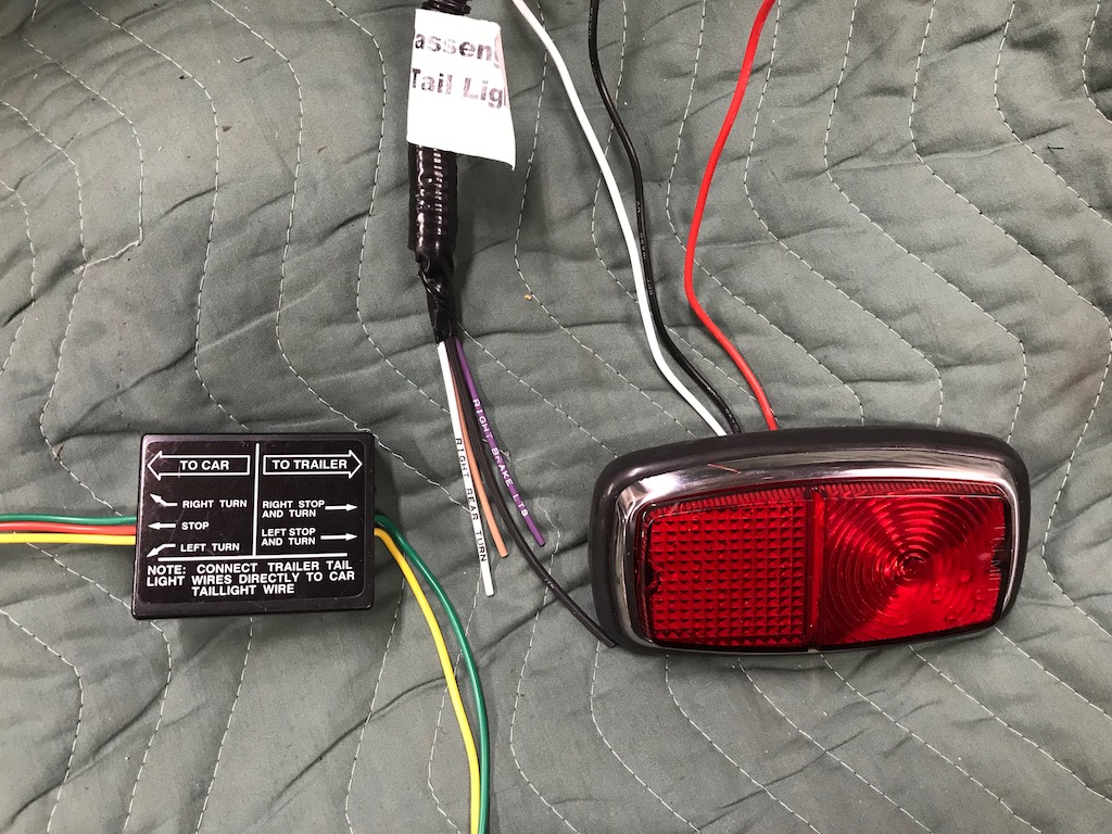
    I'm not a very smart guy. I don't understand the logic behind this magical trailer box thing. Can anyone tell me how to hook up the wiring to each of my my taillights? The picture depicts what I have. The light is an LED taillight. Thanks in advance.

    build thread: http://thefactoryfiveforum.com/showt...-USRRC-vspeeds

    Build School: July 14-16, 2017
    Kit purchased: July 25, 2017
    Kit delivered: September 13, 2017
    First Start: December 22, 2018
    Body painted and kit completed and drivable: July 2019 (but still not done)
    CA SB100 Registration: January 2020

    Mk4 - 289 USRRC Roadster kit, Roush 427SR with Schneider Racing custom camshaft, Fitech EFI, TKO600 (.64-5th gear), 15" wheels, stock brake calipers, under car exhaust with Spintech 7000 muffler, no roll bar, Russ Thompson turn signal, removable steering wheel, and many other small upgrades and modifications
  2. #2

    Join Date
    Mar 2017
    Location
    Norway / Merritt Island FL
    Posts
    159
    Post Thanks / Like
    On the To car side: The green wire connects to the white, Right Rear Turn, from the harness. The orange connects to the pink, Right Brake Light, from the harness. The yellow connects to a wire in the harness labelled Left Rear Turn. There is no need to connect the wire harness wire labeled Left Brake lLight.

    To Trailer: Green to the high power led on the right, yellow to the left.

    Ground wires connect to each other. Rear lights to low power leds.
    Last edited by Sigurd; 11-23-2018 at 03:30 AM. Reason: Spelling

  3. #3
    Senior Member Fixit's Avatar
    Join Date
    Aug 2017
    Location
    Minneapolis 'Burbs
    Posts
    910
    Post Thanks / Like
    The original setup (2 lamps/housings per side, each with dual filament bulbs) was configured to be 1 lamp/housing would do signal duty, 1 lamp/housing for stop duty - both would do parking light duty (dim filament).

    Swapping to the rectangles means the "bright" filament of the (now) single bulb/housing per side has to do both the turn & stop functions (no impact on parking light).

    The magic trailer box is a merger/traffic cop. It's "eavesdropping" on the L & R turn signal wires, and the common to both sides stop wire.

    The "stop" feed from up front is common to both sides of the car - hence only one input wire to the box. When there's voltage on this line it sends it straight through to the "bright" filaments of the lamp housings on each side using the (now) merged single "bright" output to each side.

    During a "stop with turn signal" scenario, there's voltage coming in on the "stop" wire, and (pulsed) voltage on the respective "turn" wire.
    This is where the magic happens...
    When it senses voltage on a given "turn" wire, it cuts the "stop" voltage input for that side, and allows the pulsed "turn" voltage through on the common output wire for a given side. When the pulsed turn voltage goes away (turn completed/switch off) it reconnects the stop voltage to the output wire.

    Make Sense??

    **There's a typo in Sigurd's connection explanation above...**

    The magic trailer box should probably be cut into the wiring at the back of the rear main harness where things split to the L & R of the car.
    You'll need to identify the Left Turn, Right Turn, and one of the Stop/Brake wires (doesn't matter which).


    In your case:
    The "To Car" green is spliced to the vehicle white feed wire (right turn)
    The "To Trailer" green is spliced to the leftover tail going to the lamp housing (Right side)
    The "To Car" orange is spliced to the vehicle purple feed wire (R Stop)
    (Clip and cap off the other "stop" feed wire)
    The "To Car" yellow is spliced to the vehicle L turn feed wire
    To "To Trailer yellow is spliced to the leftover tail going to the lamp housing (Left side)

    This should do it for you.

    You may have to exchange your traditional old-school thermal flashers (turn and hazard) for electronic versions. LED's don't pull enough current to heat up a thermal flasher and make it function - especially if you're replacing the fronts with LEDs as well.
    John D. - Minneapolis 'Burbs

    1965 El Camino - LT-1, 4L60e, 4wh discs, SC&C susp.
    2013 F-150 Platinum - Twin Turbo 3.5
    2018 Mk4 Roadster w/ Coyote - #9365 - Build Thread Delivery 7/3/18, 1st Start 1/4/19, 1st Road Mile 5/5/19, Legal 6/18/19, In Paint 2/25/21, Done (?) 4/2021

  4. #4

    Join Date
    Nov 2016
    Location
    Petaluma, CA
    Posts
    345
    Post Thanks / Like
    It seems we of the 289 FIA family have struggled a bit with the trailer converter and the rear tail lights. It can be made to work but there is a much simpler and more elegant solution applied by Chris on his build that I utilized on mine. You can see it on his thread here: https://thefactoryfiveforum.com/show...ild-8833/page3. It's easy, inexpensive and it works. Joel

  5. #5

    Join Date
    Apr 2017
    Location
    Elk Grove, NorCal
    Posts
    550
    Post Thanks / Like
    Quote Originally Posted by Sigurd View Post
    On the To car side: The green wire connects to the white, Right Rear Turn, from the harness. The orange connects to the pink, Right Brake Light, from the harness. The yellow connects to a wire in the harness labelled Left Rear Turn. There is no need to connect the wire harness wire labeled Left Brake lLight.

    To Trailer: Green to the high power led on the right, yellow to the left.

    Ground wires connect to each other. Rear lights to low power leds.
    Thanks Sigurd
    build thread: http://thefactoryfiveforum.com/showt...-USRRC-vspeeds

    Build School: July 14-16, 2017
    Kit purchased: July 25, 2017
    Kit delivered: September 13, 2017
    First Start: December 22, 2018
    Body painted and kit completed and drivable: July 2019 (but still not done)
    CA SB100 Registration: January 2020

    Mk4 - 289 USRRC Roadster kit, Roush 427SR with Schneider Racing custom camshaft, Fitech EFI, TKO600 (.64-5th gear), 15" wheels, stock brake calipers, under car exhaust with Spintech 7000 muffler, no roll bar, Russ Thompson turn signal, removable steering wheel, and many other small upgrades and modifications

  6. #6

    Join Date
    Apr 2017
    Location
    Elk Grove, NorCal
    Posts
    550
    Post Thanks / Like
    Quote Originally Posted by Fixit View Post
    The original setup (2 lamps/housings per side, each with dual filament bulbs) was configured to be 1 lamp/housing would do signal duty, 1 lamp/housing for stop duty - both would do parking light duty (dim filament).

    Swapping to the rectangles means the "bright" filament of the (now) single bulb/housing per side has to do both the turn & stop functions (no impact on parking light).

    The magic trailer box is a merger/traffic cop. It's "eavesdropping" on the L & R turn signal wires, and the common to both sides stop wire.

    The "stop" feed from up front is common to both sides of the car - hence only one input wire to the box. When there's voltage on this line it sends it straight through to the "bright" filaments of the lamp housings on each side using the (now) merged single "bright" output to each side.

    During a "stop with turn signal" scenario, there's voltage coming in on the "stop" wire, and (pulsed) voltage on the respective "turn" wire.
    This is where the magic happens...
    When it senses voltage on a given "turn" wire, it cuts the "stop" voltage input for that side, and allows the pulsed "turn" voltage through on the common output wire for a given side. When the pulsed turn voltage goes away (turn completed/switch off) it reconnects the stop voltage to the output wire.


    Make Sense??

    **There's a typo in Sigurd's connection explanation above...**

    The magic trailer box should probably be cut into the wiring at the back of the rear main harness where things split to the L & R of the car.
    You'll need to identify the Left Turn, Right Turn, and one of the Stop/Brake wires (doesn't matter which).


    In your case:
    The "To Car" green is spliced to the vehicle white feed wire (right turn)
    The "To Trailer" green is spliced to the leftover tail going to the lamp housing (Right side)
    The "To Car" orange is spliced to the vehicle purple feed wire (R Stop)
    (Clip and cap off the other "stop" feed wire)
    The "To Car" yellow is spliced to the vehicle L turn feed wire
    To "To Trailer yellow is spliced to the leftover tail going to the lamp housing (Left side)

    This should do it for you.

    You may have to exchange your traditional old-school thermal flashers (turn and hazard) for electronic versions. LED's don't pull enough current to heat up a thermal flasher and make it function - especially if you're replacing the fronts with LEDs as well.
    Fixit
    Thanks for the detailed explanation. Now it makes sense to me. Unfortunately, I just found out that trailer box contraption is not compatible with LED lights but I was made aware of an inexpensive alternative that "cnutting" used in his thread.
    build thread: http://thefactoryfiveforum.com/showt...-USRRC-vspeeds

    Build School: July 14-16, 2017
    Kit purchased: July 25, 2017
    Kit delivered: September 13, 2017
    First Start: December 22, 2018
    Body painted and kit completed and drivable: July 2019 (but still not done)
    CA SB100 Registration: January 2020

    Mk4 - 289 USRRC Roadster kit, Roush 427SR with Schneider Racing custom camshaft, Fitech EFI, TKO600 (.64-5th gear), 15" wheels, stock brake calipers, under car exhaust with Spintech 7000 muffler, no roll bar, Russ Thompson turn signal, removable steering wheel, and many other small upgrades and modifications

  7. #7

    Join Date
    Apr 2017
    Location
    Elk Grove, NorCal
    Posts
    550
    Post Thanks / Like
    Japollon
    Thanks for forwarding Chris's (cnutting) build thread link.
    build thread: http://thefactoryfiveforum.com/showt...-USRRC-vspeeds

    Build School: July 14-16, 2017
    Kit purchased: July 25, 2017
    Kit delivered: September 13, 2017
    First Start: December 22, 2018
    Body painted and kit completed and drivable: July 2019 (but still not done)
    CA SB100 Registration: January 2020

    Mk4 - 289 USRRC Roadster kit, Roush 427SR with Schneider Racing custom camshaft, Fitech EFI, TKO600 (.64-5th gear), 15" wheels, stock brake calipers, under car exhaust with Spintech 7000 muffler, no roll bar, Russ Thompson turn signal, removable steering wheel, and many other small upgrades and modifications

  8. #8

    Join Date
    Apr 2017
    Location
    Elk Grove, NorCal
    Posts
    550
    Post Thanks / Like
    Chris
    I got your PM. Thanks for letting me know about the workaround. I just bought those diodes on Amazon and I'll ditch the trailer box thing.
    build thread: http://thefactoryfiveforum.com/showt...-USRRC-vspeeds

    Build School: July 14-16, 2017
    Kit purchased: July 25, 2017
    Kit delivered: September 13, 2017
    First Start: December 22, 2018
    Body painted and kit completed and drivable: July 2019 (but still not done)
    CA SB100 Registration: January 2020

    Mk4 - 289 USRRC Roadster kit, Roush 427SR with Schneider Racing custom camshaft, Fitech EFI, TKO600 (.64-5th gear), 15" wheels, stock brake calipers, under car exhaust with Spintech 7000 muffler, no roll bar, Russ Thompson turn signal, removable steering wheel, and many other small upgrades and modifications

  9. #9
    Member
    Join Date
    Jun 2018
    Posts
    44
    Post Thanks / Like
    I have the same lights and a Trailer box will work but, it needs to be a powered unit. The one you have will not work.

  10. #10
    Senior Member mmklaxer's Avatar
    Join Date
    Aug 2015
    Location
    Kennebunk, ME
    Posts
    292
    Post Thanks / Like
    I am working through electrical, and thinking through the taillight trailer converter. I assumed (wrongly i supposed) that the converter would be located near the terminal, as opposed to at the "Y" of the rear harness. I have all aluminum installed and that gas tank installed. Any way to avoid dropping the gas tank at this point?

    My only other thought would be to put it in the transmission tunnel, but would just have to continuity check that I'm splicing into the correct wires
    Last edited by mmklaxer; 02-26-2023 at 08:51 AM.

Posting Permissions

  • You may not post new threads
  • You may not post replies
  • You may not post attachments
  • You may not edit your posts
  •  

Brown County Customs

Visit our community sponsor