Midwest Classic Insurance

Visit our community sponsor

Thanks Thanks:  0
Likes Likes:  0
Results 1 to 16 of 16

Thread: MK IV IRS question

  1. #1
    Junior Member
    Join Date
    Jul 2018
    Posts
    21
    Post Thanks / Like

    MK IV IRS question

    I started my kit today and decided to start with the IRS since so many parts for the front suspension are missing.

    Looking at the pictures in the manual I have mostly figured out which bolts go where (I think) but there seems to be an awful lot of exposed thread on the two gold colored (110mm) that join the lower control arm to the aluminum section.

    If these don’t go there, where do they go? I put them here based upon a photo that showed this bolt head instead of a flanged bolt head. The nuts that match these bolts also have no flanges unlike the rest of the bolts in this assembly. They also have washers that are otherwise unaccounted for and fit, but I’m not sure where they are supposed to go.

    Any ideas?

    I also have two 90mm bolts with no accompanying nuts that I have no idea where they go.

  2. #2
    Junior Member
    Join Date
    Jul 2018
    Posts
    21
    Post Thanks / Like

  3. #3
    Junior Member
    Join Date
    Jul 2018
    Posts
    21
    Post Thanks / Like
    Extra bolts that are from the lower control arm bag

    BEFFE199-ED60-4742-B4FC-FAD14A955CE2.jpg

  4. #4
    Senior Member edwardb's Avatar
    Join Date
    Feb 2011
    Location
    Lake Orion, Michigan
    Posts
    10,566
    Post Thanks / Like
    I don't think those are the right bolts. Unless something has changed. I've done two of the 2015+ IRS assemblies, and in all cases the suspension bolts were flange head bolts and flanged locknuts. For the lower control arm where you're showing the 110MM bolt, my parts list shows using a M16-2.0 x 90MM flange head bolt, part number 15909. The inner connections for the lower control arm use a 110MM bolt, M16-2.0 x 110MM to be specific, part number 14925. Also flanged. I'd be a little careful using pictures as definitive proof. Often stock pictures are used to illustrate something, but might not be exact detail for your build. (My Gen 3 Coupe manual is full of Roadster pictures...) The captions or word descriptions are usually good, if details are provided. The box-by-box inventory list is a good source IMO of these kinds of details since it has exact descriptions, part numbers, etc. usually grouped with enough information to identify exactly what it's for.
    Build 1: Mk3 Roadster #5125. Sold 11/08/2014. Build 2: Mk4 Roadster #7750. Sold 04/10/2017. Build Thread
    Build 3: Mk4 Roadster 20th Anniversary #8674. Sold 09/07/2020. Build Thread and Video. Build 4: Gen 3 Type 65 Coupe #59. Gen 3 Coyote. Legal 03/04/2020. Build Thread and Video
    Build 5: 35 Hot Rod Truck #138. LS3 and 4L65E auto. Rcvd 01/05/2021. Legal 04/20/2023. Build Thread. Sold 11/9/2023.

  5. #5
    Member
    Join Date
    Mar 2018
    Location
    Chesapeake VA
    Posts
    72
    Post Thanks / Like
    My lower control arms were/are missing 2 M16 x 2 lock nuts. I'm still waiting for FFR to reply to my request for nuts. The inventory shows 6 bolts and only 4 nuts. 4 bolts were longer for attaching the arms to the frame and the 90mm bolts attach the arms to the spindle. I did not receive the gold 110mm bolts with the control arms. So I suspect you are also missing the nuts.

  6. #6
    Junior Member
    Join Date
    Jul 2018
    Posts
    21
    Post Thanks / Like
    Well, it may be just as easy to go down to Grainger and just buy a couple nuts.....

  7. #7
    Senior Member edwardb's Avatar
    Join Date
    Feb 2011
    Location
    Lake Orion, Michigan
    Posts
    10,566
    Post Thanks / Like
    Quote Originally Posted by Saleen9165 View Post
    Any ideas?
    Quote Originally Posted by Saleen9165 View Post
    Well, it may be just as easy to go down to Grainger and just buy a couple nuts.....
    Have you called Factory Five (not email...) and talked to them about this? It's critical that you use the right parts for this assembly, and from what you're picturing and describing, you don't. This is a well proven assembly and they have all the right parts. If you don't have them, they'll get them to you. Their customer service for this kind of thing is top notch. The forums are full of examples.

    Also can't help but ask if you did a complete inventory when you received your kit? Item by item against the provided box inventory lists? Important not only to make sure you have all the parts, but is a huge help to identify what each part looks like, how they compare to the instructions, etc. Done properly, especially for first time builders (don't know if that's you...) can take a number of hours. But pays dividends throughout the build.
    Last edited by edwardb; 11-28-2018 at 05:44 PM.
    Build 1: Mk3 Roadster #5125. Sold 11/08/2014. Build 2: Mk4 Roadster #7750. Sold 04/10/2017. Build Thread
    Build 3: Mk4 Roadster 20th Anniversary #8674. Sold 09/07/2020. Build Thread and Video. Build 4: Gen 3 Type 65 Coupe #59. Gen 3 Coyote. Legal 03/04/2020. Build Thread and Video
    Build 5: 35 Hot Rod Truck #138. LS3 and 4L65E auto. Rcvd 01/05/2021. Legal 04/20/2023. Build Thread. Sold 11/9/2023.

  8. #8
    Senior Member FF33rod's Avatar
    Join Date
    Jun 2018
    Location
    North Vancouver, BC, Canada
    Posts
    1,559
    Post Thanks / Like
    Have you mounted the center section yet? I'm just doing this and the gold 110 bolts youre referring to look like the 2 bolts for the front 2 mount points of the center section.
    Steve

    Edit: just looked at the packing list this morning and the center section bolts are 130mm long, so my comment above is not applicable. But looking at the manual, it indicates that the LCA is attached to the frame using 110mm and the LCA attaches to the spindle using 90mm long.
    Last edited by FF33rod; 11-28-2018 at 12:17 PM.

  9. #9
    Member
    Join Date
    Mar 2018
    Location
    Chesapeake VA
    Posts
    72
    Post Thanks / Like
    I just spoke to FF and they are going to look at the inventory for the IRS Lower Control Arm Components. As I mentioned above, they have 6 bolts but only 4 nuts in the kit. Hopefully this will fix the problem for future builders.

  10. #10
    Junior Member
    Join Date
    Jul 2018
    Posts
    21
    Post Thanks / Like
    EdwardB,

    I did an inventory, yes. VERY thorough right down to the missing headlight trim ring screws and some missing parts in sealed assemblies even.

    I think perhaps they are not providing the proper number of bolts in their kits because my inventory shows the 90mm M16 bolts that are supposed to go on the rear knuckle / lower control arm mount, but no flanged nuts like the other mounting points have. I think perhaps the "master" packing list is off by two nuts which is why my inventory did not turn up this deficiency.

    I know now that the longer gold bolts are for the front upper control arm mount where the heim joint and misalignment spacer tie the system together. Those spacers were on my parts shortage list BTW.

    I'll call them about these missing nuts tomorrow.

  11. #11
    Senior Member lewma's Avatar
    Join Date
    Jan 2018
    Location
    San Marcos, CA
    Posts
    447
    Post Thanks / Like
    Blog Entries
    1
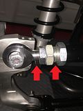
    Not sure if it will help you but here's a pic from my build earlier this year showing the bolts I used:

    20180405_230919.jpg
    Build 1: Mk4 Complete Kit #9312 Ordered 1/27/18, Delivered 3/24/18, CA SB100 Registered 9/11/19 - Gen 2 Coyote TKO600, IRS, Power Steering, Wilwood Brakes, 17" Halibrand.
    Build 2: Gen3 Coupe Complete Kit #309 Ordered 1/25/21, Delivered 6/9/21 - BluePrint GM 427 LS T56, IRS, AC, Power Steering. Album Here

  12. #12
    Senior Member edwardb's Avatar
    Join Date
    Feb 2011
    Location
    Lake Orion, Michigan
    Posts
    10,566
    Post Thanks / Like
    Quote Originally Posted by lewma View Post
    Not sure if it will help you but here's a pic from my build earlier this year showing the bolts I used:

    20180405_230919.jpg
    Neither nut pictured here has the threads going all the way through the nut. The lower control arm looks like it isn't tightened yet. The flange on the head of the bolt isn't tight against the mount. Hopefully that's the case and when tightened is OK. But if that upper control arm nut is tight, I don't think that's acceptable. You'll get different opinions, but for something as critical as a suspension joint, I would expect it to be flush at the absolute minimum, and ideally 1-2 threads exposed. Especially in this case since it's a distortion lock nut, and the locking mechanism is at the outside part of the nut. Are you positive you have the right bolts and nuts? I've done two of these, and never had a condition like that.

    Second and unrelated, just a hint. On that upper control arm camber adjustment, ideally it should be set so there's equal threads exposed on each side of the adjustment sleeve. Your is off center quite a bit. You'll only get about half the possible adjustment with it installed like that.
    Build 1: Mk3 Roadster #5125. Sold 11/08/2014. Build 2: Mk4 Roadster #7750. Sold 04/10/2017. Build Thread
    Build 3: Mk4 Roadster 20th Anniversary #8674. Sold 09/07/2020. Build Thread and Video. Build 4: Gen 3 Type 65 Coupe #59. Gen 3 Coyote. Legal 03/04/2020. Build Thread and Video
    Build 5: 35 Hot Rod Truck #138. LS3 and 4L65E auto. Rcvd 01/05/2021. Legal 04/20/2023. Build Thread. Sold 11/9/2023.

  13. #13
    Senior Member lewma's Avatar
    Join Date
    Jan 2018
    Location
    San Marcos, CA
    Posts
    447
    Post Thanks / Like
    Blog Entries
    1
    Quote Originally Posted by edwardb View Post
    Neither nut pictured here has the threads going all the way through the nut. The lower control arm looks like it isn't tightened yet. The flange on the head of the bolt isn't tight against the mount. Hopefully that's the case and when tightened is OK. But if that upper control arm nut is tight, I don't think that's acceptable. You'll get different opinions, but for something as critical as a suspension joint, I would expect it to be flush at the absolute minimum, and ideally 1-2 threads exposed. Especially in this case since it's a distortion lock nut, and the locking mechanism is at the outside part of the nut. Are you positive you have the right bolts and nuts? I've done two of these, and never had a condition like that.

    Second and unrelated, just a hint. On that upper control arm camber adjustment, ideally it should be set so there's equal threads exposed on each side of the adjustment sleeve. Your is off center quite a bit. You'll only get about half the possible adjustment with it installed like that.
    That was just an early pic trying to show the nuts/bolts that I used. It's all been tightened down since.

    Camber adjustment has not been setup yet.

    mark
    Build 1: Mk4 Complete Kit #9312 Ordered 1/27/18, Delivered 3/24/18, CA SB100 Registered 9/11/19 - Gen 2 Coyote TKO600, IRS, Power Steering, Wilwood Brakes, 17" Halibrand.
    Build 2: Gen3 Coupe Complete Kit #309 Ordered 1/25/21, Delivered 6/9/21 - BluePrint GM 427 LS T56, IRS, AC, Power Steering. Album Here

  14. #14
    Senior Member edwardb's Avatar
    Join Date
    Feb 2011
    Location
    Lake Orion, Michigan
    Posts
    10,566
    Post Thanks / Like
    Quote Originally Posted by lewma View Post
    Camber adjustment has not been setup yet.

    mark
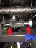
    OK, but that doesn't matter. When assembling and installing the adjuster, put it together so there are equal threads on both sides. To adjust camber, the jamb nut is loosened, and the large nut turned which moves the end of the UCA in and out. One side is standard direction threads. The other reverse direction. Like a turnbuckle. If the threads aren't the same, you could run out of threads on one side and still have threads available on the other. Same for the toe arm. Should look something like this.


    It's not well explained in the instructions, and unfortunately the mounting bolts need to be removed so they can be corrected. But once done, you won't have to take things apart again. It's one of the nice features of the newer design IRS. The previous version, in stock form, required the bolts to be removed every time it was adjusted. I'm sharing because I didn't know about this on my first build with the new IRS, and had to disassemble late in the build to correct. Just trying to help.
    Build 1: Mk3 Roadster #5125. Sold 11/08/2014. Build 2: Mk4 Roadster #7750. Sold 04/10/2017. Build Thread
    Build 3: Mk4 Roadster 20th Anniversary #8674. Sold 09/07/2020. Build Thread and Video. Build 4: Gen 3 Type 65 Coupe #59. Gen 3 Coyote. Legal 03/04/2020. Build Thread and Video
    Build 5: 35 Hot Rod Truck #138. LS3 and 4L65E auto. Rcvd 01/05/2021. Legal 04/20/2023. Build Thread. Sold 11/9/2023.

  15. #15
    Senior Member CraigS's Avatar
    Join Date
    Feb 2011
    Location
    Blacksburg, Va
    Posts
    4,724
    Post Thanks / Like
    I hate deformed metal lock nuts so I replaced all the IRS and front diff mount bolts/nuts w/ 5/8 bolts and nylock nuts. 5/8 is >004 inches smaller than 16mm. Nice that I can buy all of them at the local hardware store.
    FFR MkII, 408W, Tremec TKO 500, 2015 IRS, DA QA1s, Forte front bar, APE hardtop.

  16. #16
    Senior Member FF33rod's Avatar
    Join Date
    Jun 2018
    Location
    North Vancouver, BC, Canada
    Posts
    1,559
    Post Thanks / Like
    I did the driver's side of my '33 IRS today. As you found, I was missing 2 nuts BUT I found them in the package of hardware that was for mounting the center section so it all balanced out.

Posting Permissions

  • You may not post new threads
  • You may not post replies
  • You may not post attachments
  • You may not edit your posts
  •  

Stewart Transport

Visit our community sponsor