-
Signal Dynamics Self-Canceling Turn Signal Module Question
I'd like to wire in the SDC Self-Canceling Turn Signal Module but have a question. Can I use this for just the turn signals, not the hazards by swapping out my turn signal switch with a momentary SPDT toggle wired to the SDC module?
Thanks,
Dave
-
I'm not sure about that arrangement. I can offer you what I did in my build. I used a 2 position momentary (on)-off-(on) for my turn signal, and ran jumper wires to the hazard switch. This is because both wires need to be energized for the signal module to turn on the hazards.
It may not be what you need, but here is how I wired it. I cannot find the electronic copy of how the hazard switch is wired, but I'm pretty sure I used the one from FFR.
See attached.FFR 6882 WIRING PAGE 3.pdf
Dave
Mk 3.1 - #6882 - 5.0L 302 - FiTech EFI - 3-Link - 3.08 Ratio - 15" Wheels
Greenhorn and doing the best I can
My photos are at:
My Flickr acct
Videos are at:
YouTube Videos
-
Not a waxer

Papa,
I've used the SD module on a few cars (it's always worked flawlessly by the way) and need to think on doing it as you suggest but why not just let the module activate your flashers as well? To do so with the SPDT momentary all you need to do is to run another pigtail off of both the left and right trigger then connect one to each pole of an on/off switch. When the switch is off they are isolated for turn signal function; when the switch is on they are joined together and activating either direction on your SPDT witt put it into 4 way flasher mode. Easy peasy!
Jeff
EDIT: I see that Dad of Three Dave answered with his method while I was typing!
Last edited by Jeff Kleiner; 01-11-2019 at 03:04 PM.
-


Originally Posted by
DadofThree

I'm not sure about that arrangement. I can offer you what I did in my build. I used a 2 position momentary (on)-off-(on) for my turn signal, and ran jumper wires to the hazard switch. This is because both wires need to be energized for the signal module to turn on the hazards.
It may not be what you need, but here is how I wired it. I cannot find the electronic copy of how the hazard switch is wired, but I'm pretty sure I used the one from FFR.
See attached.
FFR 6882 WIRING PAGE 3.pdf
Originally Posted by
Jeff Kleiner
Papa,
I've used the SD module on a few cars (it's always worked flawlessly by the way) and need to think on doing it as you suggest but why not just let the module activate your flashers as well? To do so with the SPDT momentary all you need to do is to run another pigtail off of both the left and right trigger then connect one to each pole of an on/off switch. When the switch is off they are isolated for turn signal function; when the switch is on they are joined together and activating either direction on your SPDT witt put it into 4 way flasher mode. Easy peasy!
Jeff
EDIT: I see that Dad of Three Dave answered with his method while I was typing!
Thanks, guys. This sounds simple enough. Do I need to remove the flashers or disconnect and terminate the existing hazard switch/wires?
Dave
-
DadofThree,
Thanks for the schematic. I ordered a different SDC module than the one in the schematic, so here is my amateurish edited version for the SDC 01501.
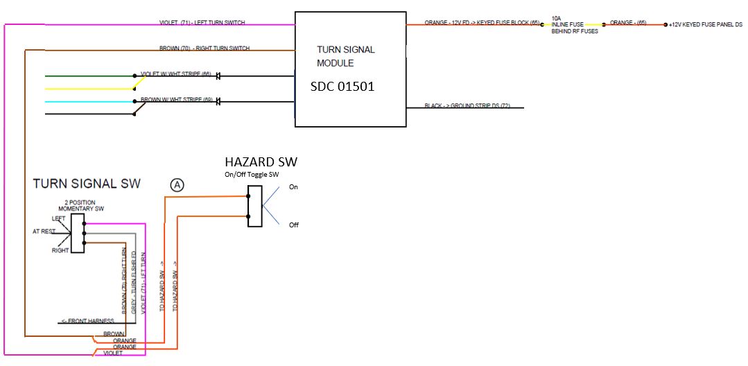
I'm still assuming that with this setup, I should pull the flashers out of the fuse panel and disconnect the current hazard switch since the SDC module controls all the flashing functions for both the turn signals and hazards.
All you automotive electrical gurus, please set me straight on anything I've overlooked or made incorrect assumptions on.
Dave
Last edited by Papa; 01-30-2019 at 08:11 PM.
-
Senior Member

I set mine up exactly as Jeff indicated above. To answer your question about the flashers, I removed both flasher units (hazards and turn signals) and shorted the terminals in the front of the fuse panel so the current would flow straight through to the lights. If i had easier access to the back of my RF fuse panel, I just would have cut the wires and done it there. The only question I would have for your diagram is why are you adding an inline fuse to the 12V source? You can just use what naturally came with the RF harness. Use the Hazard feed (pink) if you want it to run all the time, or the turn signal feed (grey) if you want it to be keyed.
Last edited by CFranks; 01-11-2019 at 06:31 PM.
-
Originally Posted by
CFranks
I set mine up exactly as Jeff indicated above. To answer your question about the flashers, I removed both flasher units (hazards and turn signals) and shorted the terminals in the front of the fuse panel so the current would flow straight through to the lights. If i had easier access to the back of my RF fluse block, I just would have cut the wires and done it there. The only question I would have for your diagram is why are you adding an inline fuse to the 12V source? You can just use what naturally came with the RF harness. Use the Hazard feed if you want it to run all the time, or the turn signal feed f you want it to be keyed.
Thanks for the info on the flashers. That's pretty much what I expected. Did you just create jumpers with spade connectors and a short piece of wire? As for the fuse, that was in the diagram DadofThree provided and is consistent with the SDC install sheet I found on their web site. It can't hurt to add a fuse. I'll likely use the electric choke circuit to power the SDC module. Before I wire the new hazard switch, I may try the SDC module with just the turn signals and keep the hazards on the existing circuit. If it creates issues, I can easily add the second on/off toggle and let the SDC control the hazards. The issue with that is that the key would need to be on to make the hazards work or I'd have to put the entire module on a constant powered circuit, which I really don't want to do.
Dave
Last edited by Papa; 01-30-2019 at 08:12 PM.
-
Senior Member
Originally Posted by
Papa
Thanks for the info on the flashers. That pretty much what I expected. Did you just create jumpers with spade connectors and a short piece of wire? As for the fuse, that was in the diagram Jeff provided and is consistent with the SDC install sheet I found on their web site. It can't hurt to add a fuse. I'll likely use the electric choke circuit to power the SDC module. Before I wire the new hazard switch, I may try the SDC module with just the turn signals and keep the hazards on the existing circuit. If it creates issues, I can easily add the second on/off toggle and let the SDC control the hazards. The issue with that is that the key would need to be on to make the hazards work or I'd have to put the entire module on a constant powered circuit, which I really don't want to do.
Dave
I just created jumpers just as you mention using spade connectors. I believe the best practice would be to cut and bypass on the back of the fuse panel, I just didn't do it that way 1) to give me a little flexibility in case this didn't work and 2) i'm working with a partially completed car and was nervous to pull out the fuse panel. I'm by NO means an electrical expert so would defer to just about anyone else on this, but I didn't see the need for another inline fuse given I used the pink hazard 12V source which was still flowing through a fuse in the RF harness (bypassing the flashers doesn't bypass the fuses for either 4-ways or turn signal...I think). As you say, no harm in adding another one though.
-


I just did this install this last week. In your schematic above, the hazard switch also needs to be momentary. And if it's a SPST, you'll need the diodes, or keep it a DPST. Jumpers: yes, 2 short pieces of wire with male spade connectors. Actually, when you pull the flashers out, you'll need spades that look just like the blades on the flashers! 
And it's an LED safe unit, so you're good to swap over your bulbs if ya want. I'm running complete LEDs, and it works great.
My hazards are powered from the battery. My turn signals are powered key on. Standard RF stuff. In order for the SD unit to function with hazards, it will need battery power and not ignition-switched power. However, with the key off, the T/S's have no power, so no big deal. If you power the SD unit off a switched source (such as TS gray), it will not work with your hazards unless the key is left on. Not a good way to do it, IMHO.
If you are going to try it with existing hazards, make sure the hazard wiring is not wired to the input side of the SD unit... the hazard wiring will have to be on the output side, bypassing the SD unit. If you decide to add the hazards into it later, that wiring will have to be changed over to the input side of the SD Unit.
-
Originally Posted by
Boydster
I just did this install this last week. In your schematic above, the hazard switch also needs to be momentary. And if it's a SPST, you'll need the diodes, or keep it a DPST. Jumpers: yes, 2 short pieces of wire with male spade connectors. Actually, when you pull the flashers out, you'll need spades that look just like the blades on the flashers!
And it's an LED safe unit, so you're good to swap over your bulbs if ya want. I'm running complete LEDs, and it works great.
My hazards are powered from the battery. My turn signals are powered key on. Standard RF stuff. In order for the SD unit to function with hazards, it will need battery power and
not ignition-switched power. However, with the key off, the T/S's have no power, so no big deal. If you power the SD unit off a switched source (such as TS gray), it will not work with your hazards unless the key is left on. Not a good way to do it, IMHO.
If you are going to try it with existing hazards, make sure the hazard wiring is not wired to the input side of the SD unit... the hazard wiring will have to be on the output side, bypassing the SD unit. If you decide to add the hazards into it later, that wiring will have to be changed over to the input side of the SD Unit.
Boyd,
Let me run this by you to see if I'm missing something. I was hoping that I could simply pull the left and right bundles off the current on-off-on toggle switch and connect them to the output side of the SDC module. I'd then use the turn signal feed (gray) wire to power the on-off-on momentary switch with the outputs of that switch connected to the inputs (triggers) of the SDC module. I'd then need to jumper the TS flasher. I'd leave the hazard flasher in place and leave the hazard wiring connected to the current 6-pin on-on switch.
Will this work?
Dave
Last edited by Papa; 01-30-2019 at 08:16 PM.
-
Originally Posted by
Papa
Boyd,
Le me run this by you to see if I'm missing something. I was hoping that I could simply pull the left and right bundles off the current on-off-on toggle switch and connect them to the output side of the SDC module. I'd then use the turn signal feed (gray) wire to power the on-off-on momentary switch with the outputs of that switch connected to the inputs (triggers) of the SDC module. I'd then need to jumper the TS flasher. I'd leave the hazard flasher in place and leave the hazard wiring connected to the current 6-pin on-on switch.
Will this work?
Dave
If you do this at the switch, the turn signals will work. HOWEVER... The RF splices for the hazard circuit into the TS circuit would be in the output wires from the SD unit. You will create a backfeed issue when using the hazards... that power will come back through the SD unit and backfeed power, which can make all kinds of really weird things happen. I had this issue... all of the power on the car was cycling at the same rate as the still-installed hazard flasher... lights, gauges, fuel injection, everything. The hazard flasher was turning the whole car on & off, on & off, on & off...
The fix to this can go two ways:
1. Use diodes in the SD unit output wires before the hazard wiring connection. Install so the blocking lines on the diodes are away from the SD unit. This will prevent a backfeed from the hazards into the SD Unit.
2. Install new wires from the hazard switch output to the TS switch output (disconnect and stow the old hazard switch output wires). This will wire the hazard switch on the input side of the SD unit. Use a momentary DPST or DPDT hazard switch and jumper the hazard flasher.
You can try it the way you wrote, but be prepared for a real WTF moment. Maybe it was just my car, but it seems like the internal design of the unit has nothing to prevent electrons from going backwards.
Last edited by Boydster; 01-13-2019 at 11:14 AM.
-
-
Those are cool! And yes, you'd be able to totally get rid the hazard switch and wiring, since the SD unit says to press both TS buttons at the same time for hazards. Nice find. If my switch panel wasn't already designed, made, covered and installed, I might have used this.
-
With the separate switches, here is what I'm thinking it should look like integrated into the RF harness:
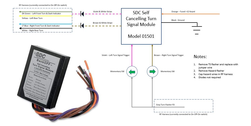
I ordered some diodes, but don't know that they are necessary. It can't hurt to put them in-line with the output to the lamps. Also, I believe I can still leave the complete RF hazard circuit in place (switch and flasher) and activate the hazards via the constant +12v supply vs. the SDC switched +12v supply if needed. If that causes issues, I can disable that circuit per my notes.
Last edited by Papa; 01-13-2019 at 03:13 PM.
-
Using the diagram above, if you disable the RF hazard circuit and dont use it, then use the 2 buttons together to engage hazards, your key will have to be on for hazards to work.
If you use the RF hazard circuit, install the diodes close to the SD unit outputs from the box. That way you know the RF hazard splices are down line. Doing it this way, the hazards are working off battery (no key) and the SD Unit is not even powered.
I installed my SD Unit powered off the RF Hazard power wire (flasher removed and jumpered). That way the hazards work through the SD Unit off battery power. The Leds keep the draw very low, so I'm not overloading anything.
I used 2ea 5A 30V Shottky diodes to isolate the circuits and they work great. But I'm also using all LED.
Last edited by Boydster; 01-13-2019 at 05:05 PM.
-
Post Thanks / Like - 1 Thanks, 0 Likes
 Papa
Papa thanked for this post
-
Originally Posted by
Boydster
Using the diagram above, if you disable the RF hazard circuit and dont use it, then use the 2 buttons together to engage hazards, your key will have to be on for hazards to work.
If you use the RF hazard circuit, install the diodes close to the SD unit outputs from the box. That way you know the RF hazard splices are down line. Doing it this way, the hazards are working off battery (no key) and the SD Unit is not even powered.
I installed my SD Unit powered off the RF Hazard power wire (flasher removed and jumpered). That way the hazards work through the SD Unit off battery power. The Leds keep the draw very low, so I'm not overloading anything.
I used 2ea 5A 30V Shottky diodes to isolate the circuits and they work great. But I'm also using all LED.
Thanks, Boyd. I'm going to give this a shot once I have all the parts here. I'm going to try to keep the RF hazard circuit in place as it is now and only worry about the SDC unit controlling the turn signals. Although, if it works, I should be able to activate hazards via the SDC module as long as the key is on. I appreciate you taking the time to review my plan.
Dave
-
No problem, man. I had just done it so it was fresh in my mind. Dont ask me how I wired up my tail lights with the trailer converter.
Post back on how it all works so it keeps the thread complete for historical purposes.
Car is looking good in the build thread!
-
Member

Originally Posted by
Papa
Papa,
Those are awesome looking. Did you order them from that website Blue Wire Automotive? They are in Australia it looks like or did you find them on the states? Is that the power window switches cause that is all I could find on their site. I kinda want to order all the switches like that to match for head lights and maybe a push button start etc. I like the idea of the self canceling signals.
-
I actually ordered similar switches that cost a lot less from Billet Automotive Buttons.
https://billetautomotivebuttons.com/...down-indicator
They are also in Australia. They have a ton of options if you are looking for a matching set for several functions. I'll try making my own aluminum plate for them, but if that doesn't look good, I'll mount them directly into the dash.
Dave
Last edited by Papa; 01-14-2019 at 11:33 AM.
-
I used a switch like this for my horn button, and hooked up the led to the dash lighting so I can see it at night. That thing is BRIGHT. Its the brightest light on my dash. The guy 2 cars over could read by it. I may install a resistor to dim it down or possibly disconnect the LED completely.
Disclaimer... dont know if these are that bright or not, but be prepared. Yowza.
-
The ones I bought don't have any lighting. For the ones I've looked at that do, a few have recommended adding resistors to get the voltage down to the recommended low voltage for the LEDs.
-
Post Thanks / Like - 0 Thanks, 1 Likes
-
Member

-
Post Thanks / Like - 1 Thanks, 1 Likes
-
Originally Posted by
Boydster
I used a switch like this for my horn button, and hooked up the led to the dash lighting so I can see it at night. That thing is BRIGHT. Its the brightest light on my dash. The guy 2 cars over could read by it. I may install a resistor to dim it down or possibly disconnect the LED completely.
Disclaimer... dont know if these are that bright or not, but be prepared. Yowza.
Boyd -- One of these might do the trick for you.
https://bluewireautomotive.com/produ...-dimmer-module
Dave
-
Originally Posted by
Papa
Boyd -- One of these might do the trick for you.
Thanks Dave. Its certainly cheap enough to try, isnt it...
-
In an effort to keep this thread current all the way to completion, here is a quick update. I have everything for the install except for the switches that should be delivered today. While sitting here watching the blizzard blowing outside this morning, I decided to get what I could done with the parts I have sitting on my desk. I soldered a pair of diodes to the output wires on the SDC unit and added some 22 gauge male spade connectors that I'll be able to directly plug the RF turn signal bundles to.

My soldering skills are pretty amateur-level, but they are solidly connected and covered in clear heat shrink.
-
Post Thanks / Like - 0 Thanks, 1 Likes
-
I'm pleased to update this thread with a successful implementation of the SDC Self-Cancelling turn signal module. I installed it exactly per the wiring diagram I posted above. I also left the RF hazard circuit completely in tact and it works as intended. So, I can activate the four-way flashers via either the SDC unit or the RF circuit. The RF circuit will operate with the car off and the key removed, but the SDC module will only operate with the key in the on position. This can be handy for some cases when you need flashers while you are in the car. I'll be posting more details of the switches and plate I used in my build thread.
-
Post Thanks / Like - 1 Thanks, 1 Likes
-
Great Job Dave!
I just ran across your video on YouTube 
Dave
Mk 3.1 - #6882 - 5.0L 302 - FiTech EFI - 3-Link - 3.08 Ratio - 15" Wheels
Greenhorn and doing the best I can
My photos are at:
My Flickr acct
Videos are at:
YouTube Videos
-
Thanks. It is exactly what I had hoped it would be.
Dave
-
Dave,
Thanks for completing the thread and, more importantly, for your very detailed and well-thought out questions / comments / diagrams and photos. I intend to follow your plan closely on my build.
Well done!
Craig
10/2018 -- acquired Mk3.1 #6602 which was an unfinished project in go-kart stage; 9/2019 -- completed car enough to drive locally and compete in autocross events; still in original black gel-coat; 347 Stroker w/ Holley 650 carb, roller cam; Tremec 3550; 3.51 rear diff; lots of Breeze pieces; 2021 -- XP Champion in Central PA Region - SCCA Autocross Series; 2022 - installed windshield and registered in PA; my Build Thread -- https://thefactoryfiveforum.com/show...ished-Business
6/2022 -- acquired Mk3 #1004; finished build; 347 stroker w/ Holley 560 carb SOLD
-
Post Thanks / Like - 2 Thanks, 0 Likes
-
Hi all, want to resurrect this thread a bit. So we have SDS module 01501 and a momentary toggle switch for turn signals. My idea would be to have separate turn signal and flashers switches on a dashboard, operating independently. What would be the correct way to wire them using SDS module? Would set up from post #18 work for a toggle momentary switch?
Build thread
FFR mk4 roadster complete kit, 347 cu in carbed BluePrint engine, TKO600, IRS, power steering, ordered Jan2020, delivered 3/25/20, titled 8/23/20, finished 07/17/2021,
graduated 10/06/2021
-
Originally Posted by
alexmak
Hi all, want to resurrect this thread a bit. So we have SDS module 01501 and a momentary toggle switch for turn signals. My idea would be to have separate turn signal and flashers switches on a dashboard, operating independently. What would be the correct way to wire them using SDS module? Would set up from post #18 work for a toggle momentary switch?
Post #5 of this thread may be your answer. Post #2 is what I did with my SD unit (not a 01501)
Last edited by DadofThree; 06-01-2020 at 11:56 AM.
Dave
Mk 3.1 - #6882 - 5.0L 302 - FiTech EFI - 3-Link - 3.08 Ratio - 15" Wheels
Greenhorn and doing the best I can
My photos are at:
My Flickr acct
Videos are at:
YouTube Videos
-
Originally Posted by
alexmak
Hi all, want to resurrect this thread a bit. So we have SDS module 01501 and a momentary toggle switch for turn signals. My idea would be to have separate turn signal and flashers switches on a dashboard, operating independently. What would be the correct way to wire them using SDS module? Would set up from post #18 work for a toggle momentary switch?
If you really want to keep it simple, do what I did and leave the FFR hazard circuit completely independent of the SDC turn signal circuit. Here is my final diagram of what I implemented:
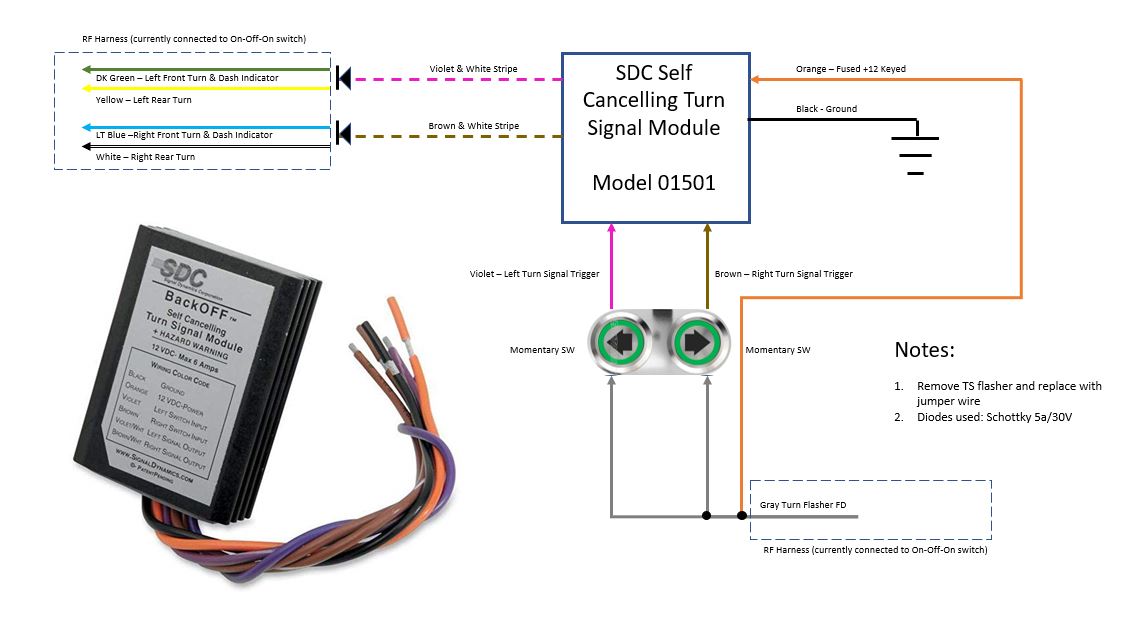
Note that I can use this to turn on the flashers by pressing both turn signal momentary switches simultaneously (with the key on). I can also activate the real hazard circuit by flipping the hazard toggle switch with the key on or off.
-
Post Thanks / Like - 2 Thanks, 1 Likes
-
Senior Member

I wired in a on-off-on momentary toggle switch on my dash for my turn signals. I thought this would best replicate the movement in a normal DD car, placing it on the left side of my dash; flipping up for right turn and flipping down for left turn. I did use the gray RF dash harness wire, which is powered when keyed on.
For my hazards, I used a momentary push button switch under my dash in one of my dash supports (or underdash support if you have it) and wired it to the pink hazard power from the RF dash harness. This wire is hot all the time. I figured that it would be most convenient to have the hazards run without needing key on. Just jumper wires from one side of your push button to the violet and brown wires (needs to be DPST switch) with (pink wire) power going to each side of the other pole. Initially I thought I could use a SPST switch, but it was pointed out to me that the violet and brown wires cannot cross/touch.
I wanted to keep my dash minimalistic so putting the button under the dash just to my left worked out great.20200124_152526.jpg
Last edited by egchewy79; 06-01-2020 at 08:22 PM.
-
Originally Posted by
egchewy79
I wanted to keep my dash minimalistic so putting the button under the dash just to my left worked out great.
Same here. My hazard switch, wiper switch, speedo function switch, and gauge dimmer knob are all under the dash in the dash supports as well. My clock set button is in the glove box.

-
we also want to keep it as minimalistic as possible. Will add one switch for turn signals here and the rest are going to be under the dash in dash support panel
IMG_8850.jpg
Build thread
FFR mk4 roadster complete kit, 347 cu in carbed BluePrint engine, TKO600, IRS, power steering, ordered Jan2020, delivered 3/25/20, titled 8/23/20, finished 07/17/2021,
graduated 10/06/2021
-
Thanks for this thread Papa!
While I have the body off for paint, I'm improving several items and turn signals is one of those items. I followed your lead on almost everything except the Diode placement.
Here is where I deviated,
Instead of putting the diodes before the SD unit, I just used a Diode as a jumper at the fuse box across the Turn Signal Flasher.
I wanted to make sure that this was ok so I contacted Signal Dynamics and they had this response:
Turn Signal Module 01501 Technical Question.
1. I am using this module for Turn Signals Only
2. I am using the Turn Signal Power line from the Fuse Box that is powered when the Ignition is on.
3. The Turn Signal Power line has a Diode to prevent power from going back into the fuse box
4. I have a separate switch for the Hazards.
5. The Hazard Power Supply from the Fuse Box is Hot at all times so I can run the hazards with the ignition off.
6. Both systems power the same signal lights on the same wires.
Question: Will it hurt your turn signal module if the 12V power (that will go to the signal lights when the Hazards are on) is allowed to go through your module back to the diode upstream of the Orange 12v wire (from the striped turn signal wires that go to the lights)?
Here was the answer they gave:
What you propose will not hurt our module. It is tolerant of any voltage between 0VDC and 12VDC on any wire.
-
Originally Posted by
RRussellTx
Thanks for this thread Papa!
While I have the body off for paint, I'm improving several items and turn signals is one of those items. I followed your lead on almost everything except the Diode placement.
Here is where I deviated,
Instead of putting the diodes before the SD unit, I just used a Diode as a jumper at the fuse box across the Turn Signal Flasher.
I wanted to make sure that this was ok so I contacted Signal Dynamics and they had this response:
Turn Signal Module 01501 Technical Question.
1. I am using this module for Turn Signals Only
2. I am using the Turn Signal Power line from the Fuse Box that is powered when the Ignition is on.
3. The Turn Signal Power line has a Diode to prevent power from going back into the fuse box
4. I have a separate switch for the Hazards.
5. The Hazard Power Supply from the Fuse Box is Hot at all times so I can run the hazards with the ignition off.
6. Both systems power the same signal lights on the same wires.
Question: Will it hurt your turn signal module if the 12V power (that will go to the signal lights when the Hazards are on) is allowed to go through your module back to the diode upstream of the Orange 12v wire (from the striped turn signal wires that go to the lights)?
Here was the answer they gave:
What you propose will not hurt our module. It is tolerant of any voltage between 0VDC and 12VDC on any wire.
Fantastic! It's easy to move the diode(s) if they don't work the way you plan to do them, and I wasn't 100% sure they are needed at all using the SDC module, but figured it was cheap insurance.
-
Originally Posted by
Papa
Fantastic! It's easy to move the diode(s) if they don't work the way you plan to do them, and I wasn't 100% sure they are needed at all using the SDC module, but figured it was cheap insurance.
For the others that follow, a diode is required!
I learned this fact when my fuel pump came on when I turned on the Hazards and the key was off...


 Thanks:
  Likes:


 Reply With Quote
