I've done a search on the subject, but I'm still unclear as to exactly this is connected into the RF harness. I've been told to add a fusable link from the battery connection to the alternator, which is confusing me even more. In the RF harness there are two reasonably substantial red wires that end at a plug, and another plug with lighter gauge red and black, (or brown) wires that end at another plug. The alternator has one connection lug, and a ground(?) lug. So what connects to what? I'm using an MSD ignition, and a FAST FI, not sure if that's relevant or not, but...
Anyhow, I'm getting close to doing this wiring, and I get less comfortable the more I think about it. I really should have paid closer attention in those electronics classes in high school! Although after 50+ years, I doubt I'd remember any of it anyway.
Rick
Mk4 with Mr. Bruce FIA body, 331 w/ Speedmaster Stack Injection, Full Width Roll Bar with high brake lights by i.e.427, IRS, ABS, PS, PB, FAST FI, First start 3/30/20, First go-kart 7/5/20, paint by Ken Pike
All you need is the 2 large red wires. the rest you can disregard. If your alt. is high amp (140) you may just want to run a battery cable size wire to the starter.
Wallace, On the two large red wires, does one loop back to the battery wire connection? I'm not sure where these wires go, and that's after looking at the wiring diagram in the RF book! Or are you saying to replace those two wires with a battery cable sized wire to the battery cable connection? Does it need connection to anything else? What protects the system from the alternator failing and sending too many amps through the system? I really suck at the wiring part of this build.
Rick
Mk4 with Mr. Bruce FIA body, 331 w/ Speedmaster Stack Injection, Full Width Roll Bar with high brake lights by i.e.427, IRS, ABS, PS, PB, FAST FI, First start 3/30/20, First go-kart 7/5/20, paint by Ken Pike
OK, I'm going to try to respond again. The computer froze up half way through my response, and had to completely shut down to get it to work again.
cv2065, You're doing an absolutely beautiful job an your build! Unfortunately, I wasn't able to determine what I needed to do from what I could see in the pictures.
GFX, I was pretty sure I needed to do that, but just not sure how to go about it. I am, after all is said and done, wiring challenged!
Thanks guys.
Rick
Mk4 with Mr. Bruce FIA body, 331 w/ Speedmaster Stack Injection, Full Width Roll Bar with high brake lights by i.e.427, IRS, ABS, PS, PB, FAST FI, First start 3/30/20, First go-kart 7/5/20, paint by Ken Pike
Get a 175a mega bus fuse and holder from del city and wire it in between the alternator power wire and starter. Single wire alternators are simple and work fine. I’m running one myself and I have no issues with it. If your not using a battery cutoff you can run all the power wires through the starter battery terminal.
Mk4, Moser M88 rear end, Eaton truetrak, Craft Racing 461 Windsor, MMR pro trans, Glenns 1,000 hp cobra fuel system and lots of other parts.
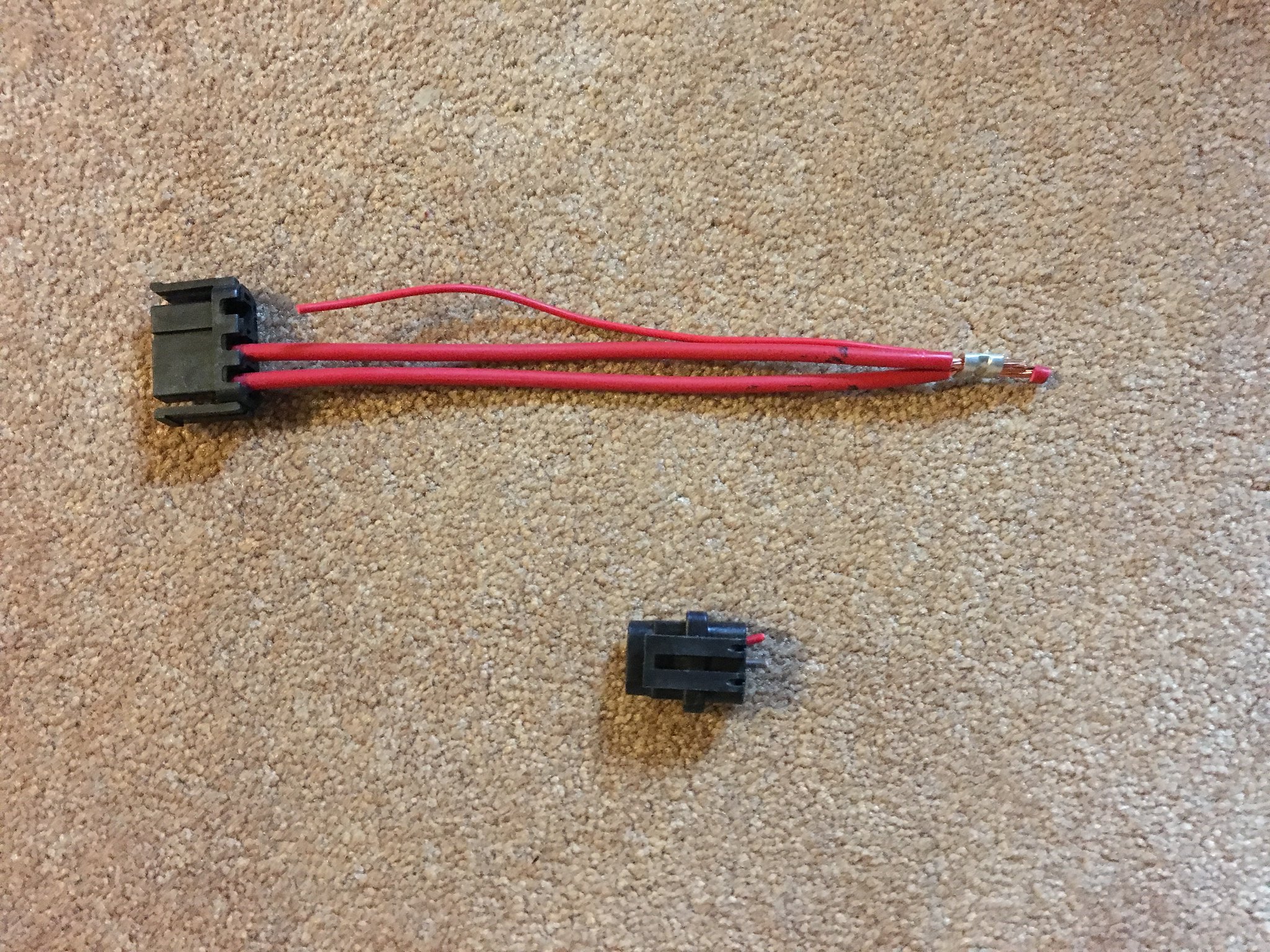
1. Peel the plastic loom back on the two alternator feed wires until they reach a splice where they should be attached/spliced to a single larger wire.
2. If this is what you discover, you can simply cut off the two smaller wires and splice in a single larger wire of the larger gauge.
3. Put a connector on the sucker, wrap it up with some plastic loom and your conversion is complete.
NOTE: This is assuming that the Ron Francis Harness is the same as the one that I got back in the day.
Gfx, I'm running a battery cutoff switch, so I'll either come off that, or like GoDadGo mentioned, just modify the RF harness. I think I'm starting to get the idea of how this works, which kind of worries me sice I have such a horrible lack of knowlege about the electrical! Thanks guys.
Rick
Mk4 with Mr. Bruce FIA body, 331 w/ Speedmaster Stack Injection, Full Width Roll Bar with high brake lights by i.e.427, IRS, ABS, PS, PB, FAST FI, First start 3/30/20, First go-kart 7/5/20, paint by Ken Pike
FYI, If your using a cutoff switch the battery and alternator wire need to go to one side and a cable the same size as the battery needs to go from the other side of the switch to the starter. The wire harness power wires either need to go to tge starter power post or the side of the switch where the starter cable is hooked up. Otherwise there is no point to the switch as it won’t work.
Mk4, Moser M88 rear end, Eaton truetrak, Craft Racing 461 Windsor, MMR pro trans, Glenns 1,000 hp cobra fuel system and lots of other parts.
I'm not using a cut-off switch or maxi fuse, but the following may be helpful (adapted from Post #230 & 251 of my build log):
I eliminated the alternator branch on my Ron Francis wiring harness. NOTE: This will only work if youre using a one-wire alternator AND if youre solenoid is integrated with your starter motor.
The RF instructions tell you to run the alternator wires along the top of the engine to the alternator. They also state that if youre using a one-wire alternator to cut the large plug off the wires and attach two 10-12 ga. ring connectors to the two large wires and attach them to the post on the alternator. The other plug and wires are not used.
Im using a one-wire alternator, so I did as instructed. In the process, I discovered that all of the red wires coming out of the alternator branch joined a couple of inches from the far end of the branch.
It didnt make any sense to me to connect two wires to the alternator that joined not eight inches later, so I cut those out as well.
That left me with a single 8 ga. wire to get through the firewall, and a smaller brown wire that wasnt going to be used.
My starter solenoid is integrated with the starter as an assembly; that is to say, I dont have an external solenoid, so I suspected the 8 ga. wire could probably be routed more efficiently. I traced this and the brown wire back towards the fuse box (unwrapping the harness as I went), and discovered that the small brown wire is supposed to be connected to the ignition switch, and that the 8 ga. wire came from the starter solenoid.
I left the brown wire in place on the ignition switch branch (in case I lose my mind and replace the one-wire alternator with a 1987-1993 Mustang one). I removed the 8 ga. wire from the starter solenoid branch and replaced it with the brown wire (so that it now goes from the ignition switch to the trunk of the harness and then down the starter solenoid branch to my starter motor). I folded the end of the brown wire over on itself and sealed the end with heat shrink. That way its mostly in place if I ever need it.
I then re-wrapped everything on the harness that I took apart. I still have to re-secure the starter solenoid branch along the underside of the firewall forward. Thats going to be a bear with the bell housing blocking access.
I ran the alternator wire through the valley between the carburetor and the valve cover, around the back side of the engine, and down to my mini starter. That eliminated at least 5 feet from a 100A electrical run.
GFX, I figured that would be the case on the alternator wire, and that is how the cutoff switch is wired.
John, Again, thanks for the great write up. It really explained a lot.
GoDadGo, No worries, my solenoid is on the starter as well. And don't feel bad about how long it's been since you owned a Ford, I haven't owned a Chevy since my '57 that I bought in 1968!
Rick
Mk4 with Mr. Bruce FIA body, 331 w/ Speedmaster Stack Injection, Full Width Roll Bar with high brake lights by i.e.427, IRS, ABS, PS, PB, FAST FI, First start 3/30/20, First go-kart 7/5/20, paint by Ken Pike
GFX, I figured that would be the case on the alternator wire, and that is how the cutoff switch is wired.
John, Again, thanks for the great write up. It really explained a lot.
GoDadGo, No worries, my solenoid is on the starter as well. And don't feel bad about how long it's been since you owned a Ford, I haven't owned a Chevy since my '57 that I bought in 1968!
Have never owned a chevy car, gone keep it that way.
OK, change of plans. Decided to go ahead and use the existing RF alternator wiring. It's already connected everywhere else, and I see no purpose served by tearing it all out at this point. I did remove the extra wire as John detailed, and in talking to Gordon, I got a 10 gauge fusable link wire as he suggested. My question is, can I install this at the end that connects to the post on the alternator, or does it need to go somewhere else? Also, since the two wires are different gauges, what would be the best way to connect them together? As a note, it turns out that it is a 100 amp alternator.
Thanks.
Rick
Mk4 with Mr. Bruce FIA body, 331 w/ Speedmaster Stack Injection, Full Width Roll Bar with high brake lights by i.e.427, IRS, ABS, PS, PB, FAST FI, First start 3/30/20, First go-kart 7/5/20, paint by Ken Pike
Fuse location doest matter to much but if it is a mega buss you typically bolt them to something so they don’t shake around as they are kinda big. For connecting wires you should solder and heat shrink them. The heat shrink tubing if selected correctly will shrink and seal both wire sizes.
Mk4, Moser M88 rear end, Eaton truetrak, Craft Racing 461 Windsor, MMR pro trans, Glenns 1,000 hp cobra fuel system and lots of other parts.
Mk4 with Mr. Bruce FIA body, 331 w/ Speedmaster Stack Injection, Full Width Roll Bar with high brake lights by i.e.427, IRS, ABS, PS, PB, FAST FI, First start 3/30/20, First go-kart 7/5/20, paint by Ken Pike
What am I missing here? I simply ran the red alternator wire from the RF harness to the alternator. The brown wire isn't used. I ran a ground from the alternator to the engine block. Done!
What am I missing here? I simply ran the red alternator wire from the RF harness to the alternator. The brown wire isn't used. I ran a ground from the alternator to the engine block. Done!
Dave and cv2065, basically the same thing here, but for circuit protection, Gordon recommended that I add a fusible link, instead of a mega fuse, in the alternator wire, and I just wasn't sure if there was a specific location in the run that was recommended. After cutting out the extra red wire that connects about a foot back, and folding over and shrink wrapping the brown wire, as John said "in case I lose my mind and change to a 2G, 3G", I soldered the fusible link onto the end of the red alt wire, added an eyelet, and connected it to the alternator. I hope I'm done with this, but the way things usually go around here, I probably forgot something, and I'll be taking it apart again!
Rick
Mk4 with Mr. Bruce FIA body, 331 w/ Speedmaster Stack Injection, Full Width Roll Bar with high brake lights by i.e.427, IRS, ABS, PS, PB, FAST FI, First start 3/30/20, First go-kart 7/5/20, paint by Ken Pike
Normal for DD's to have something on the charging circuit to protect the wiring harness and/or battery in case of an alternator failure. Typically a fusible link. Not a bad idea to follow this practice on our builds with either a fusible link or a mega fuse. I've gone the mega fuse route on my builds. Mandatory? No. Lots are built without one. And alternators that fail in a way that damage things is admittedly rare. But they're used for a reason and certainly don't hurt anything.
Last edited by edwardb; 05-01-2019 at 07:49 PM.
Build 1: Mk3 Roadster #5125. Sold 11/08/2014. Build 2: Mk4 Roadster #7750. Sold 04/10/2017. Build Thread Build 3: Mk4 Roadster 20th Anniversary #8674. Sold 09/07/2020. Build Thread and Video. Build 4: Gen 3 Type 65 Coupe #59. Gen 3 Coyote. Legal 03/04/2020. Build Thread and Video Build 5: 35 Hot Rod Truck #138. LS3 and 4L65E auto. Rcvd 01/05/2021. Legal 04/20/2023. Build Thread. Sold 11/9/2023.
Dave and cv2065, basically the same thing here, but for circuit protection, Gordon recommended that I add a fusible link, instead of a mega fuse, in the alternator wire, and I just wasn't sure if there was a specific location in the run that was recommended. After cutting out the extra red wire that connects about a foot back, and folding over and shrink wrapping the brown wire, as John said "in case I lose my mind and change to a 2G, 3G", I soldered the fusible link onto the end of the red alt wire, added an eyelet, and connected it to the alternator. I hope I'm done with this, but the way things usually go around here, I probably forgot something, and I'll be taking it apart again!
Originally Posted by edwardb
Normal for DD's to have something on the charging circuit to protect the wiring harness and/or battery in case of an alternator failure. Typically a fusible link. Not a bad idea to follow this practice on our builds with either a fusible link or a mega fuse. I've gone the mega fuse route on my builds. Mandatory? No. Lots are built without one. And alternators that fail in a way that damage things is admittedly rare. But they're used for a reason and certainly don't hurt anything.
Got it. Is the fusible link typically placed right at the alternator, so I could just replace the last 6" or so of the alternator wire? Also, what gauge is best for this application?
Papa Dave, Gordon told me to order the Pico fusible link on Summit. The one he told me to get is the brown jacketed link. Since the alternator wire is, I believe, a 6 gauge, the fusible link is a 10 gauge! Go figure. Actually, everything I read said it should be 4 wire gauges smaller than the wire you're trying to protect. OK, that's about my maximum amount of knowlege about the electrical!!
Rick
Mk4 with Mr. Bruce FIA body, 331 w/ Speedmaster Stack Injection, Full Width Roll Bar with high brake lights by i.e.427, IRS, ABS, PS, PB, FAST FI, First start 3/30/20, First go-kart 7/5/20, paint by Ken Pike
Before retiring I was a Mercury Marine dealer. They had a recall on some of the Merc racing engines that involved adding a fuse in the charging circuit that never had protection previously. I'm guessing there were some "incidents" that prompted this change. FWIW. As I type this I am reminded of an incident I had while working on a pretty high dollar boat. While doing some electrical system trouble shooting I somehow managed to get a ground across the alternator connection. It only took a second to totally smoke the wiring harness. It took me 2 days to rewire the darned thing.
Got it. Is the fusible link typically placed right at the alternator, so I could just replace the last 6" or so of the alternator wire? Also, what gauge is best for this application?
Thanks,
Dave
Can't help with the gauge size. Depends on the main cable size, alternator rating, etc. I haven't used a fusible link in these builds. Only a firewall mounted mega fuse as already mentioned. The fusible links in DD's I've seen weren't typically at the alternator. They were closer to the battery or the car's power distribution box. Not sure I'd want a small gauge wire between the end of the large cable and the alternator in the heat and vibration of the engine compartment. But that's just an opinion.
Last edited by edwardb; 05-02-2019 at 05:42 AM.
Build 1: Mk3 Roadster #5125. Sold 11/08/2014. Build 2: Mk4 Roadster #7750. Sold 04/10/2017. Build Thread Build 3: Mk4 Roadster 20th Anniversary #8674. Sold 09/07/2020. Build Thread and Video. Build 4: Gen 3 Type 65 Coupe #59. Gen 3 Coyote. Legal 03/04/2020. Build Thread and Video Build 5: 35 Hot Rod Truck #138. LS3 and 4L65E auto. Rcvd 01/05/2021. Legal 04/20/2023. Build Thread. Sold 11/9/2023.
All good to know! I'll order a mega amp fuse holder and fuse. Shouldn't be hard at all to install it right before the distribution block. If the alternator is 100 amp, is the 100 amp fuse enough or does it have to be larger?
All good to know! I'll order a mega amp fuse holder and fuse. Shouldn't be hard at all to install it right before the distribution block. If the alternator is 100 amp, is the 100 amp fuse enough or does it have to be larger?
That's what I've done. Matched the mega fuse to the alternator rating. Probably the fuse could be slightly larger than the alternator. But I've stayed conservative. Plus the ANL fuses I've used while not specifically slow blow, are designed to have a delay based on the percentage of rated current.
Build 1: Mk3 Roadster #5125. Sold 11/08/2014. Build 2: Mk4 Roadster #7750. Sold 04/10/2017. Build Thread Build 3: Mk4 Roadster 20th Anniversary #8674. Sold 09/07/2020. Build Thread and Video. Build 4: Gen 3 Type 65 Coupe #59. Gen 3 Coyote. Legal 03/04/2020. Build Thread and Video Build 5: 35 Hot Rod Truck #138. LS3 and 4L65E auto. Rcvd 01/05/2021. Legal 04/20/2023. Build Thread. Sold 11/9/2023.
OK, the more I continue to think about this, the use of a fusible link, the more uncomfortable I'm getting with the thought of a 10 gauge wire in this circuit, no matter that the charts show that 10 gauge will handle 100A up to a 10 foot length. I'm going to try to post a link to a mega fuse holder that I found that is intended to be attached at the battery. Since mine is in the trunk, I like the idea that I could mount it in there, and it would be out of harms way regarding water, etc., so here goes... https://www.ebay.com/itm/100-AMP-ANL...ss!94583!US!-1
I'm assuming that no matter where in the circuit that you place the fuse, or fusible link, that the circuit and wiring will be protected from any higher amperage. If so, seeing as how this piece may assist me on another issue I'm trying to correct, does it look like it would be a good choice, or should I just get one that I can splice into the alternator wire under the hood? Damn I wish I understood the electrical better.
Rick
Mk4 with Mr. Bruce FIA body, 331 w/ Speedmaster Stack Injection, Full Width Roll Bar with high brake lights by i.e.427, IRS, ABS, PS, PB, FAST FI, First start 3/30/20, First go-kart 7/5/20, paint by Ken Pike
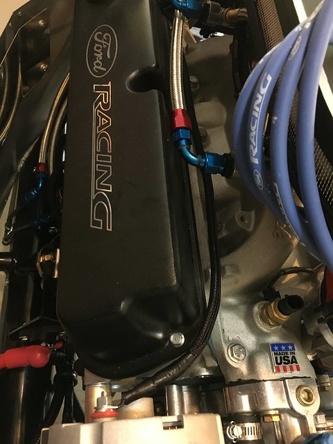
Yes, the fuse location is important. The purpose of the fuse is to protect the wiring. You therefore want the fuse as far upstream (or as close to the current source) as you can get it. In this case that means you want the fuse close to the alternator. The photo below shows one possible location. The mega fuse is fairly massive, so something substantial is needed to mount it. The passenger side motor mount fits the bill, plus it’s readily accessible (even with the engine installed), and is within about one foot of the alternator so the length of unprotected wire is minimized.
--
MKIV Roadster #8641
Complete Kit with IRS, Eaton Detroit Truetrac, 3.55 gears, Wilwood Brakes
Ford Racing Z427 w/ Pro-M Sequential Port EFI System
TKO 600 + McLeod Midshifter; Fast Freddie's Electro-Hydraulic power steering
Miller Customs Bodywork & Paint
Thanks Karlos. That is one of the parts of the protection scenario that I wasn't too clear on. Since I have a FFMetals firewall forward, I think I'll mount it to the underside just above the bellhousing. It'll be accessible, but kind of out of sight. I already have enough stuff visible in the engine bay, I don't want to add any more.
Rick
Mk4 with Mr. Bruce FIA body, 331 w/ Speedmaster Stack Injection, Full Width Roll Bar with high brake lights by i.e.427, IRS, ABS, PS, PB, FAST FI, First start 3/30/20, First go-kart 7/5/20, paint by Ken Pike
The fusible link will be just fine. Just make sure its between 5-1/2" to 6" long. Even though you have a 100 amp alternator it does not supply that many amps to charge the battery. Actual output is load dependent, the one wire alternator will never generate more current than is called for by the momentary demands of the electrical system. Example pics attached, ignore the dash light wire.


 Thanks:
  Likes:


 Reply With Quote