Very Cool Parts

Visit our community sponsor

Thanks Thanks:  0
Likes Likes:  0
Results 1 to 13 of 13

Thread: Bump steer adjustment problem

  1. #1
    Member eseethal's Avatar
    Join Date
    Jun 2011
    Location
    Salzburg/Austria/Europe
    Posts
    60
    Post Thanks / Like

    Bump steer adjustment problem

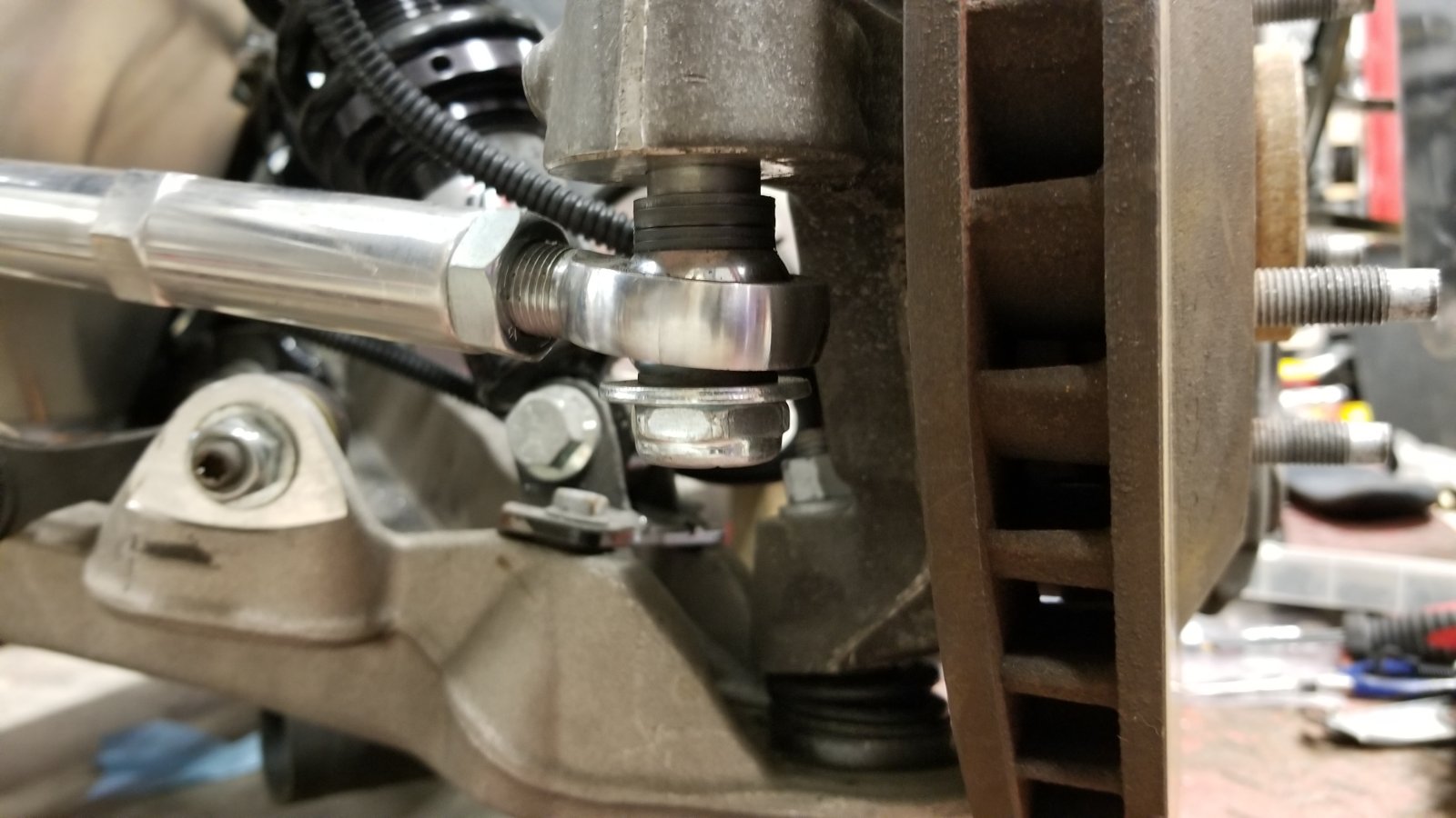
    Dear all, I need help! Fully motivated I ordered a bump steer kit from FFR to adress bump steer but it seems that the adjustment is not enough. There is quite a lot of toe in on compression and toe out in rebound. The curve is really not a curve but linear from toe in to toe out.
    Even with 6 shims between the tie rod end it is still much to high. I did a bump steer measurement before installing it and there is no difference. I don't think the the setting length is higher than with the original part. Please see picture.
    Here is a short video of the measurement through the suspension travel, quick&dirty, see the laser point on the garage wall: https://youtu.be/gL0RyjKDj3o
    Am I missing something here? Is there another way to reduce toe in on compression? Raising the inner tie rod is probably not the easiest solution.
    Thanks for your help!

    Eugen


    tie rods.jpg
    GTM #006 (early beta)
    On the road in Austria/Europe
    LS-7 with Kooks / G50 / Pfadt Bushings
    Bilstein shocks, C6 ZO6 brakes with DBA rotors
    Lightweight build (2.336 lbs ready to drive)

  2. #2
    Senior Member beeman's Avatar
    Join Date
    Feb 2011
    Location
    Indiana
    Posts
    1,490
    Post Thanks / Like
    My suspension is modified, but here is what my drivers side looks like so far (temporary setup with aluminum spacer, still playing with the settings)

    Do you need a bigger stack of washers? Which steering rack do you have.

    Last edited by beeman; 05-27-2019 at 05:07 PM.
    MK3.1 2004 Mach 1 donor. ABS, PS, TC.
    GTM #304 LPE 525hp LS3
    2000 C5 Lingenfelter LS1@489hp
    1999 Corvette FRC/Z06 track car

  3. #3
    Senior Member Roger Reid's Avatar
    Join Date
    Feb 2011
    Location
    Caldwell (near Boise) Idaho
    Posts
    237
    Post Thanks / Like
    I seem to remember the same thing on my GTM. Can you slide the dust boot of your steering rack outward and see the inside joint? Can that joint be adjusted outward? Can an extension be placed there to move the pivot outward?
    Just an old man with a great hobby

  4. #4
    Member eseethal's Avatar
    Join Date
    Jun 2011
    Location
    Salzburg/Austria/Europe
    Posts
    60
    Post Thanks / Like
    Thanks, for more washers the bolt is too short, even with the supplied 6 washers the self locking nut barely is flush with the end of the threads. I think it is the stock steering rack I use (I bought the kit partially complete and assembled). See picture of the steering rack.


    Quote Originally Posted by beeman View Post
    My suspension is modified, but here is what my drivers side looks like so far (temporary setup with aluminum spacer, still playing with the settings)

    Do you need a bigger stack of washers? Which steering rack do you have.
    steering.jpg
    Last edited by eseethal; 05-28-2019 at 04:39 AM.
    GTM #006 (early beta)
    On the road in Austria/Europe
    LS-7 with Kooks / G50 / Pfadt Bushings
    Bilstein shocks, C6 ZO6 brakes with DBA rotors
    Lightweight build (2.336 lbs ready to drive)

  5. #5
    VRaptor SpeedWorks, LLC's Avatar
    Join Date
    Feb 2011
    Posts
    1,454
    Post Thanks / Like
    I believe that the original FFR bumpsteer kit came with extensions for the inner tie rod ends that moved the pivot point outboard.
    Shane Vacek
    VRaptor SpeedWorks, LLC
    www.vraptorspeedworks.com
    Turn-key GTM, SL-C & Ultima GTR Built to Your Specs!
    Offering a full line of GTM Upgrades and Custom Parts

  6. #6
    Member eseethal's Avatar
    Join Date
    Jun 2011
    Location
    Salzburg/Austria/Europe
    Posts
    60
    Post Thanks / Like
    Shane, thanks, but unfortunately, no - there were no other parts in the FFR kit I ordered a year ago. But regarding this article (linked below) I should only move the linkage points downwards (at the wheel) or upwards (at the rack).

    Bump_Steer.pdf
    GTM #006 (early beta)
    On the road in Austria/Europe
    LS-7 with Kooks / G50 / Pfadt Bushings
    Bilstein shocks, C6 ZO6 brakes with DBA rotors
    Lightweight build (2.336 lbs ready to drive)

  7. #7
    Senior Member beeman's Avatar
    Join Date
    Feb 2011
    Location
    Indiana
    Posts
    1,490
    Post Thanks / Like
    On my roadster, I used Breeze offset steering rack aluminum bushings to shift the location of the rack, I think the GTM uses the same (Ford Mustang) based rack? Has anyone tried that? They look like this

    MK3.1 2004 Mach 1 donor. ABS, PS, TC.
    GTM #304 LPE 525hp LS3
    2000 C5 Lingenfelter LS1@489hp
    1999 Corvette FRC/Z06 track car

  8. #8
    Member eseethal's Avatar
    Join Date
    Jun 2011
    Location
    Salzburg/Austria/Europe
    Posts
    60
    Post Thanks / Like
    Oh, wow, thanks, I did not know about the existence of these parts. Good idea!
    GTM #006 (early beta)
    On the road in Austria/Europe
    LS-7 with Kooks / G50 / Pfadt Bushings
    Bilstein shocks, C6 ZO6 brakes with DBA rotors
    Lightweight build (2.336 lbs ready to drive)

  9. #9
    Junior Member
    Join Date
    May 2015
    Posts
    11
    Post Thanks / Like
    any luck yet? I'm having the same issue

  10. #10
    Member eseethal's Avatar
    Join Date
    Jun 2011
    Location
    Salzburg/Austria/Europe
    Posts
    60
    Post Thanks / Like
    Sorry, I gave up (other projects were more important) but I will start playing with my bump steer again sometimes this year.
    GTM #006 (early beta)
    On the road in Austria/Europe
    LS-7 with Kooks / G50 / Pfadt Bushings
    Bilstein shocks, C6 ZO6 brakes with DBA rotors
    Lightweight build (2.336 lbs ready to drive)

  11. #11
    Junior Member
    Join Date
    May 2015
    Posts
    11
    Post Thanks / Like
    Quote Originally Posted by eseethal View Post
    Sorry, I gave up (other projects were more important) but I will start playing with my bump steer again sometimes this year.
    I feel like the steering rack needs lifted up higher by my measurements. Then the rear tie rods need lowered some. I would like to hear from others before modifying.

  12. #12
    Senior Member
    Join Date
    Sep 2015
    Location
    Hamersville, Ohio
    Posts
    797
    Post Thanks / Like
    Bump steer is indicative of the rack being mounted either too low or too high. Your tie rod should be about parallel with your lower a-arm. There are lots of other factors in play, but this will tell you if you’re close.
    The imaginary line drawn from upper a-arm pivot thru the lower a-arm pivot should intersect your inner tie rod pivot.
    An imaginary line drawn from the a-arm pivots thru their respective ball joint should intersect. This is your ‘aiming point’ for the tie rod alignment. An imaginary line drawn from the inner tie rod pivot should intersect with the outer tie rod pivot as it extends towards the ‘aim point’.

  13. #13
    Member
    Join Date
    Dec 2017
    Location
    Dallas county, TX.
    Posts
    81
    Post Thanks / Like
    Quote Originally Posted by VRaptor SpeedWorks, LLC View Post
    I believe that the original FFR bumpsteer kit came with extensions for the inner tie rod ends that moved the pivot point outboard.
    Anyone have any pics of these extensions?

    My bad, just googled these and there are a ton of them. I had never seen or heard of........
    Last edited by HardRocker; 04-24-2020 at 12:28 AM.

Posting Permissions

  • You may not post new threads
  • You may not post replies
  • You may not post attachments
  • You may not edit your posts
  •  

FFMetal

Visit our community sponsor