-
Gen III Wiring
I am getting to the point of starting wiring and I am feeling a bit apprehensive. This is the big step in my mind where I may shoot myself in the foot without realizing it until too far down the line. I have been reading threads and see a couple main options on where to mount the main control unit and I am not sure which way to go to have the simplest install. I am not trying to reinvent anything and would like to keep it as simple as possible with as few variables for mistakes as possible. One of the locations that is different then in the manual seems to be done by some really experienced builders. On one hand, I like to follow these guys when possible as they always have a reason for what they are doing and they know what they are doing. One of the reasons to mount in a different location then the manual seems to be related to not having the harness show in the interior. I guess I am not super concerned with this if it makes things a lot easier. What do you guys recommend for a new builder who is figuring this stuff out as he goes? I don't have any experience with this beyond plugging in harnesses with simple instructions that I could not screw up in the past. I am going to be going with a gen 2 Coyote I believe and do not have the Coyote control pack yet if that matters. Let me know if I should just go ahead and order that now before I order the engine. I was thinking of getting the wiring in place before ordering the motor, so I have as long a warranty as possible and did not waste that time with it sitting in the corner of my garage for too long. Thanks.
Last edited by Tree; 07-02-2019 at 11:13 PM.
-
Senior Member

I've done two Coyote installations. One in a Roadster and one in Gen 3 Coupe. I assume by "main control unit" you're talking about the Powertrain Control Module (PCM). With the Roadster and without any big harness changes, it tucks up under the fender and is mostly hidden. The Coupe not so much because everything is out in the open when the front nose or cowl is raised. First, there are no instructions that I'm aware of from Factory Five for a Coyote installation in the Coupe. Gen 3 or otherwise. So you're a little on your own adapting the instructions for other models to the Coupe. No big deal, just be aware. The "natural" location for the PCM is based on the engine wiring harness. Not the control pack harness. The two main connections from the engine (one a very large multi-pin connector, the other smaller) terminate near the front RH side of the engine and don't reach much further. That's where the PCM is located in a Mustang, and the engine harness reflects that. So guys that have located the PCM on/near the firewall or even behind the dash have modified the engine harness. Some say not a big deal. Unlace everything and pull it all toward the back. But I haven't tried it and if you're looking for the simplest install, may not be your best choice. You'll have to decide. On an aside note, my Gen 3 Coupe build is a Gen 3 Coyote, which has even more engine wiring because of the Direct Injection (DI). Even more reason I didn't try to re-route the engine harness. A second issue with moving the PCM is the control pack harness legs are quite long. If you move the PCM back you'll have a bunch of harness to deal with. Again, not a big deal. Guys typically coil it up and hide it somewhere. Way too many conductors to even consider shortening IMO. As you may have seen in my Coupe build thread, I mounted the PCM facing up on the RH side of the engine on top of the frame. Proudly there for all to see. That was after several other location considerations. I was a little concerned about the appearance at first. But now with everything else in there, it kind of blends into the whole picture. You'll have to decide what is the best balance between aesthetics and ease of installation.
One other issue specifically for the Coupe regarding the PCM location -- don't underestimate the space required for other stuff, specifically heat and A/C if you're planning that. Between the components, wiring, and ducting, the dash becomes a very busy place. Aside from space, you'll want the PCM to be accessible and removable if necessary. If/when Ford needs to update or troubleshoot your PCM, it has to be sent to them.
As far as waiting for the engine and installing the control pack now, personally I'd advise against that. I know that opinion mainly reflects my build style where I mock up everything first. But there are a lot of moving pieces with a Coyote, especially as I've found out in a Coupe where it typically also as heat, A/C, PS, etc. and the frame design limits some of the options. I'm way more comfortable having the engine in place and working around it getting everything optimized as best I can. In your case, I'd especially recommend this approach since you say you're a bit uncomfortable and unsure about this aspect. And especially I wouldn't wait if you have any ideas about changing the engine harness to relocate the PCM. I get it about the warranty concern. Unless you're going to have the engine sitting around and burning up the entire warranty without ever running it, I wouldn't be too concerned about that. These engines have proven to be very reliable and your chance of any type of issue is very low IMO.
Last edited by edwardb; 07-03-2019 at 06:58 AM.
Build 1: Mk3 Roadster #5125. Sold 11/08/2014.
Build 2: Mk4 Roadster #7750. Sold 04/10/2017.
Build Thread
Build 3: Mk4 Roadster 20th Anniversary #8674. Sold 09/07/2020.
Build Thread and
Video.
Build 4: Gen 3 Type 65 Coupe #59. Gen 3 Coyote. Legal 03/04/2020.
Build Thread and
Video
Build 5: 35 Hot Rod Truck #138. LS3 and 4L65E auto. Rcvd 01/05/2021. Legal 04/20/2023.
Build Thread. Sold 11/9/2023.
-
I will admit as a first time builder on the Gen 3 Coupe with Gen 2 Coyote, wiring was my biggest challenge. I chose to put the PCM in the firewall because of the clean and symmetrical look. I mounted the PDB below it on the firewall and suspended the harness coiled up above the trans behind the firewall. The PCM location does create interference issues with the dash switches, but can be managed. In particular, the headlight switch is quite large. I did do some modification to the harness to allow this, but it was not technically challenging. I benefited from installing and removing the engine a few times for mock-up. Ultimately, I did most of the work with it in, but out would have been better. The hardest part for me was what wires go where. I would get a good understanding of part of the harness and then the next week it would get fuzzy again. Finally, I started taking notes and drawing my own diagrams and that was helpful. Try your best to understand what all wires are and what they do, especially the ones involved in starting. I bought a Powerprobe and that was very helpful in a lot of ways. Also, just get a good battery tender now because you are going to need it. If you have a gel battery, spend the money for the appropriate tender( ie, Ultima). Lastly, the forum was my best resource for assistance and it was in a surprisingly timely manner( thank you EdwardB).
Last edited by jdavis500; 07-03-2019 at 08:16 AM.
-
Senior Member

I'm going through this process right now. My engine is mounted in the car and the most logical place for me given where all the engine harness and PCM harness wires meet is to mount it on the back side of the passenger-side front wheel well/engine bay aluminum. As edwardb mentions, that spot can be a little tight due to the A/C connections, but I think I can make it work— seems easier to cut and re-route A/C hose if needed than it does lots and lots of tiny wires. Most likely I'll mount it with some rubber vibration dampers directly to the aluminum (although this might be overkill).
Couldn't agree more with edwardb on another point— wait until you have all the wires in hand and engine in before you commit to anything.
The engine wiring seems really tough at first glance, but in reality I think its bark is worse than its bite — everything has a nicely labeled connector and I'm mostly certain the connectors will only fit into their respective spots. So it's really just a matter of plugging things in until there is nothing left to plug in (slight oversimplification) 
Last edited by Alphamacaroon; 07-03-2019 at 11:40 AM.
-
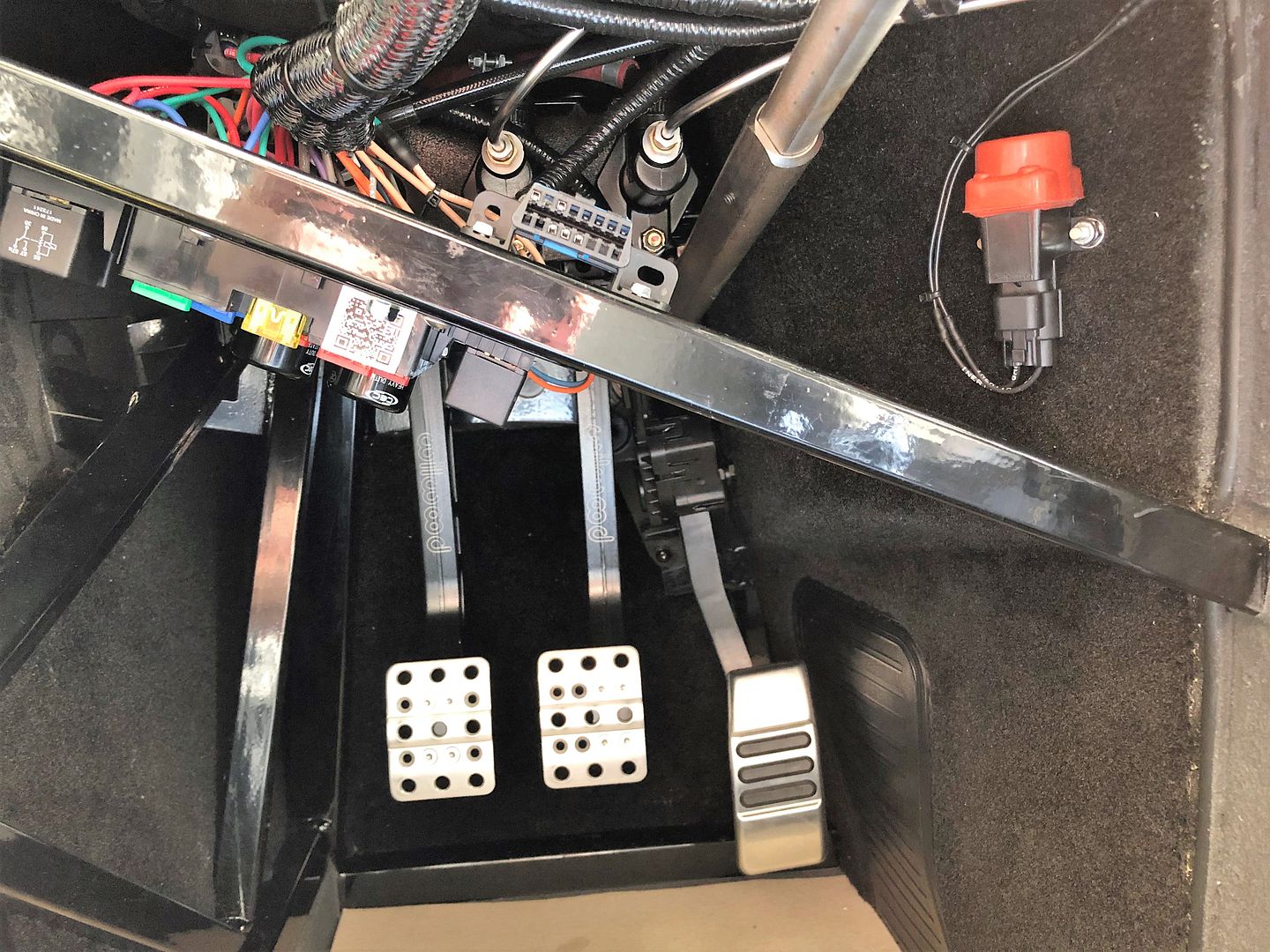
I played around with placing the harness and fuses today and it does not seem like there is a ton of room for the wiring harness if you mount it as shown. Seems like the harness would interfere with the master cylinder hoses and run into the top of the footbox. Too me, it seemed to fit better turned upside down so the fuses face up and would be visible and accessible if you make that top footbox panel removable like many builders including myself have done. Maybe I don't understand how it should be mounted or problems I would run into. I took some pictures of what I was thinking of but I am not sure if it would be best to push it as far to the outside of the car or more to the inside so I can mount it on the cross bar on the frame. I don't have the steering in yet to tell if there will be interference but I figured people on here could let me know what would be best.
What do you think? As far outside as it will go?
IMG_1038.jpg
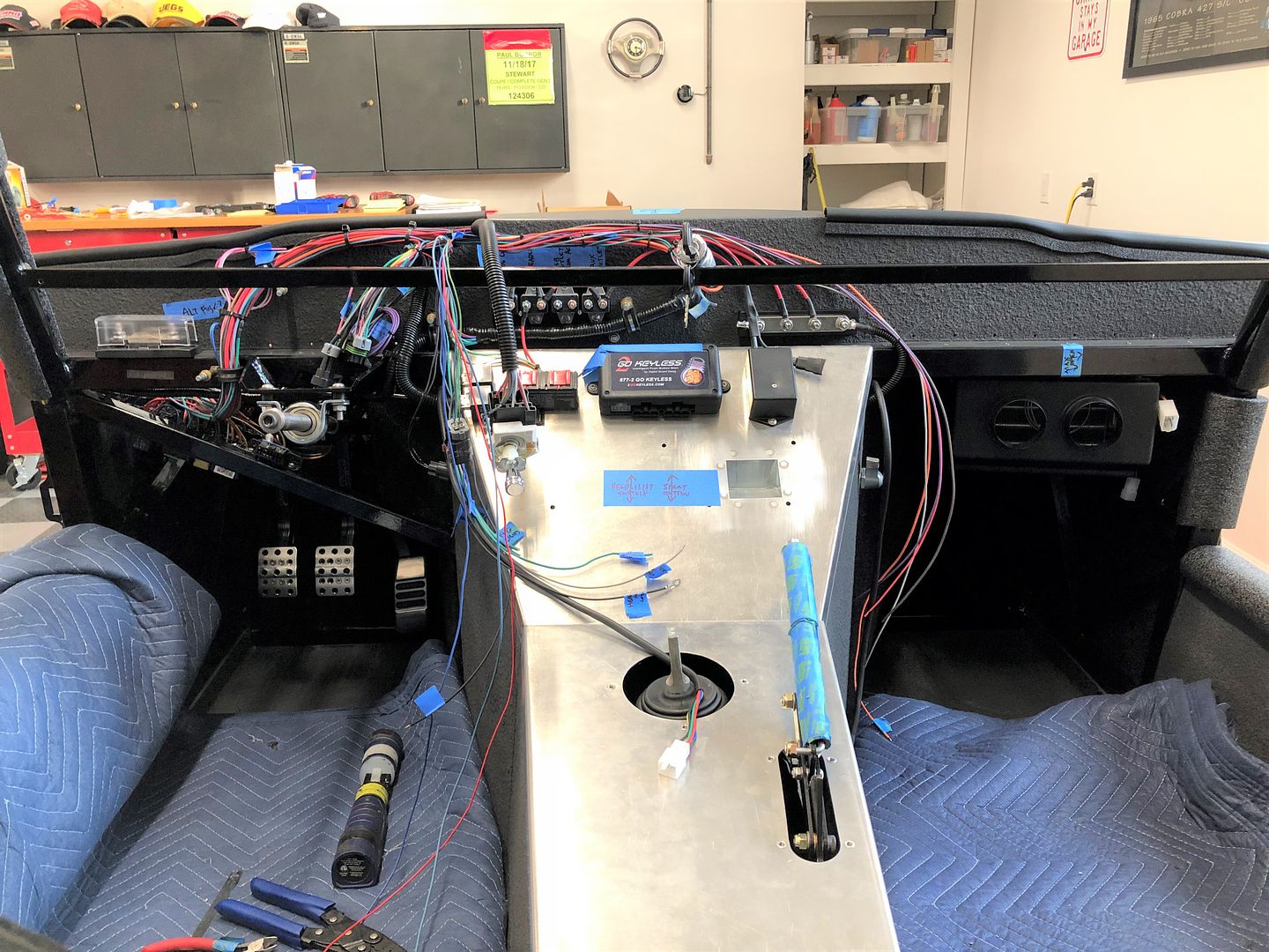
Or mounted more to the middle of center of the car using the cross bar of the frame for an additional mount and moving the connection to the front harness closer to the firewall where I will feed it through.
IMG_1041.jpg
Below if a picture of the wiring harness going underneath. Will I have any clearance issues running to the middle of the car and through the firewall? Do I need to mount the harness and fuses the other way with the fuses down? There sure is not a ton of room in that driver footbox area with the peddle box in there already.
IMG_1040.jpg
Last edited by Tree; 07-06-2019 at 11:55 PM.
-
Senior Member
I sure wouldn't mount the fuse panel that way. That's a huge trade-off in convenience (my opinion) to have to remove the access panel every time you need to get to the fuse panel. Not only the access panel, but I assume you know that area is also under where the body extends past the firewall. So you don't even have a direct view into it. Not even sure how much it helps the congestion in there anyway. Plus you still have other parts to go, like the Coyote wiring, PDB, fuel lines, etc. Mounting the fuse panel face down on that diagonal bar maybe looks a little clunky, but the wires don't interfere with the footbox or MC's. And everything else fits. Just takes some planning and large doses of patience. Here's mine FWIW. You can see a couple cables going across the MC area. But one is the Coyote DBW and the other clutch hydraulic line. I did take the Ron Francis and Coyote harnesses apart and shorten/clean things up a bit. But that's also because I chose to jam a bunch of other stuff in there, like a headlight control module, keyless start, T-56 module, additional A/C hoses, etc. But the location of the fuse panel itself didn't interfere. More pictures in my build thread with all this cleaned up and finished.
Last edited by edwardb; 07-07-2019 at 06:59 AM.
Build 1: Mk3 Roadster #5125. Sold 11/08/2014.
Build 2: Mk4 Roadster #7750. Sold 04/10/2017.
Build Thread
Build 3: Mk4 Roadster 20th Anniversary #8674. Sold 09/07/2020.
Build Thread and
Video.
Build 4: Gen 3 Type 65 Coupe #59. Gen 3 Coyote. Legal 03/04/2020.
Build Thread and
Video
Build 5: 35 Hot Rod Truck #138. LS3 and 4L65E auto. Rcvd 01/05/2021. Legal 04/20/2023.
Build Thread. Sold 11/9/2023.
-
Post Thanks / Like - 1 Thanks, 0 Likes
 Tree
Tree thanked for this post
-
Thanks Paul/EdwardB. I am glad you said something. I have now moved the fuse panel to have the fuses mounted down and I have temporarily mounted it to the diagonal frame piece as you showed. Mine is a bit more to the right due to my master calendar lines but I think it should be okay.
I ordered a Astro Pneumatic Tool 9478 Weather Pack Interchangeable Ratcheting Crimping Tool & Accessory Set (220 Piece) from Amazon today and plan to use it for connections. When I went through build school, they showed us the WeatherPack connections, which I liked. I hope that the starter kit I ordered will work out okay. Figured I would also need to order a few larger 5 or 6 pin connections for the larger items but I have not figured out exactly what I need yet. I figure the starter pack will give me most of what I need.
I think you guys also talked me into ordering the engine earlier. I am going to talk to Mike Forte on Monday. Kind of tricky timing wise for me. I have some time in the next two weeks before I get busy again and I kind of doubt that if I order everything tomorrow I will have it before I get busy. Guess I waited a bit longer then I should have there but at least I will have everything at that point and hopefully won't get stuck. Thanks again for the help everyone.
-
Senior Member
Not to confuse things, but here's another option:
IMG_0195.jpg
IMG_4994.jpg
To me this seemed like the least likely place to interfere with hydraulic lines and least likely for me to accidentally shove a foot or knee into it. The pictures make it hard to tell, but it's really tucked out of the way from legs and knees. It's also nice because you can easily see what fuse you're changing without having to turn your head upside down. I modified the mount slightly by cutting a half round notch on the top and covering it with weatherstrip to allow the wires to "nest" into it.
So far I'm really happy with it, although I am thinking that the door strap also mounts there (maybe someone else can confirm?), but it shouldn't be a problem to drill a couple more holes.
Last edited by Alphamacaroon; 07-07-2019 at 02:18 PM.
-
Senior Member

Originally Posted by
Alphamacaroon

So far I'm really happy with it, although I am thinking that the door strap also mounts there (maybe someone else can confirm?), but it shouldn't be a problem to drill a couple more holes.
Interesting. Agreed that's more convenient to see the panel, fuses, etc. Shows there's always lots of creative ideas and different approaches. Don't know that it's any less likely to be disturbed by knees or feet though. I thought the same thing when mounting the panel on the diagonal like I saw in several prototypes and copied on mine. But after climbing in and out of it a bunch of times (interior is essentially complete with seats mounted, etc.) knees don't go anywhere close. Feet either for that matter. Unless I'm falling, which hasn't happened yet and hope to keep it that way. Yes, that location will interfere with the location shown in the manual for the door check strap. They show it centered between the two hinges. Could be lowered I guess. You'll figure something out.

Build 1: Mk3 Roadster #5125. Sold 11/08/2014.
Build 2: Mk4 Roadster #7750. Sold 04/10/2017.
Build Thread
Build 3: Mk4 Roadster 20th Anniversary #8674. Sold 09/07/2020.
Build Thread and
Video.
Build 4: Gen 3 Type 65 Coupe #59. Gen 3 Coyote. Legal 03/04/2020.
Build Thread and
Video
Build 5: 35 Hot Rod Truck #138. LS3 and 4L65E auto. Rcvd 01/05/2021. Legal 04/20/2023.
Build Thread. Sold 11/9/2023.
-
Any chance you remember what box the LED flasher relays were located in? I can't find mine anywhere.
-
Mine came in a POL box. They are plastic instead of metal and have ground wires coming from the top of them in a blue package. Each flashed is packaged separately. Good luck. Finding the parts is probably a quarter of the battle sometimes.
-
FFR Maven

Originally Posted by
Alphamacaroon
The most logical place for me given where all the engine harness and PCM harness wires meet is to mount it on the back side of the passenger-side front wheel well/engine bay aluminum.
I’ve just started wiring my Gen 3 Coupe with Gen 3 Coyote. About 30 minutes in, so mostly just draping wires across the engine and seeing where things land. I too noticed the PCM would mount easily to the backside of the RH wheel aluminum. I’m planning to fabricate a couple mounts with foam vibration dampers and mount the PCM here. Did you end up doing yours this way? Any interference to the AC lines or other components?
-
Senior Member
Originally Posted by
Logan
I’ve just started wiring my Gen 3 Coupe with Gen 3 Coyote. About 30 minutes in, so mostly just draping wires across the engine and seeing where things land. I too noticed the PCM would mount easily to the backside of the RH wheel aluminum. I’m planning to fabricate a couple mounts with foam vibration dampers and mount the PCM here. Did you end up doing yours this way? Any interference to the AC lines or other components?
Hi Logan, I didn't end up mounting it there— it was too crowded with A/C lines and other stuff. I ended up mounting mine to the frame behind the radiator and am really happy with it. I have some details here: https://thefactoryfiveforum.com/show...-Mounting-Idea
Cheers,
--jim
Build 1: Gen III Type 65 Coupe, Gen II Coyote


 Thanks:
  Likes:


 Reply With Quote


