-
Senior Member

Wow, thanks Paul.
Surprised FFR doesn’t have a solution of some type for this.
Think I’m gonna put the engine in and come back to this problem.....
25th Anniversary Roadster #12 of 25
Gen 3 Coyote
TKO 600 mid-shift
Car
-
Post Thanks / Like - 0 Thanks, 1 Likes
-
Senior Member
I did email FFR too, so I guess we'll see what they say.
25th Anniversary Roadster #12 of 25
Gen 3 Coyote
TKO 600 mid-shift
Car
-
Senior Member


Originally Posted by
delta0014

Wow, thanks Paul.
Surprised FFR doesnt have a solution of some type for this.
Think Im gonna put the engine in and come back to this problem.....
Originally Posted by
delta0014
I did email FFR too, so I guess we'll see what they say.
Just to confirm, I never spoken with FFR or asked them about this issue. I had my Gen 3 Coyote before they had one, and running before they were offering it. As of today, no instructions for the Gen 3 Coyote on their website. So maybe someone there would know about this. But I've been dealing directly with Ford Performance, whose engineers have actually written the code and should be able to answer.
Build 1: Mk3 Roadster #5125. Sold 11/08/2014.
Build 2: Mk4 Roadster #7750. Sold 04/10/2017.
Build Thread
Build 3: Mk4 Roadster 20th Anniversary #8674. Sold 09/07/2020.
Build Thread and
Video.
Build 4: Gen 3 Type 65 Coupe #59. Gen 3 Coyote. Legal 03/04/2020.
Build Thread and
Video
Build 5: 35 Hot Rod Truck #138. LS3 and 4L65E auto. Rcvd 01/05/2021. Legal 04/20/2023.
Build Thread. Sold 11/9/2023.
-
Post Thanks / Like - 0 Thanks, 1 Likes
-
Senior Member
Originally Posted by
edwardb
Just to confirm, I never spoken with FFR or asked them about this issue. I had my Gen 3 Coyote before they had one, and running before they were offering it. As of today, no instructions for the Gen 3 Coyote on their website. So maybe someone there would know about this. But I've been dealing directly with Ford Performance, whose engineers have actually written the code and should be able to answer.
You would definitely think Ford could answer the questions about the code popping up...
25th Anniversary Roadster #12 of 25
Gen 3 Coyote
TKO 600 mid-shift
Car
-
Post Thanks / Like - 0 Thanks, 1 Likes
-
Senior Member
I ran to Lowe's to figure out what size the threads are. The sensor in the engine is a M12 x 1.5.
Speedhut Gauges sells a M12 x 1.5 to 1/8 inch. I might try that.
They want more for shipping then the actual part costs.... 
Last edited by delta0014; 10-25-2019 at 01:00 PM.
25th Anniversary Roadster #12 of 25
Gen 3 Coyote
TKO 600 mid-shift
Car
-
Post Thanks / Like - 0 Thanks, 1 Likes
-
-
Senior Member
Originally Posted by
Papa
How did people build these cars before Amazon and the internet in general??????
25th Anniversary Roadster #12 of 25
Gen 3 Coyote
TKO 600 mid-shift
Car
-
Post Thanks / Like - 0 Thanks, 2 Likes
-
Senior Member
Good for you guys. You found adapters. I didn't even try. Would have been better than what I did. But still begs the question -- based on what I'm seeing actually running and driving mine, the stock sensor needs to be there. Then add the Speedhut for the gauge. If you just replace, well, already explained what will happen...
Build 1: Mk3 Roadster #5125. Sold 11/08/2014.
Build 2: Mk4 Roadster #7750. Sold 04/10/2017.
Build Thread
Build 3: Mk4 Roadster 20th Anniversary #8674. Sold 09/07/2020.
Build Thread and
Video.
Build 4: Gen 3 Type 65 Coupe #59. Gen 3 Coyote. Legal 03/04/2020.
Build Thread and
Video
Build 5: 35 Hot Rod Truck #138. LS3 and 4L65E auto. Rcvd 01/05/2021. Legal 04/20/2023.
Build Thread. Sold 11/9/2023.
-
Senior Member
Originally Posted by
edwardb
Good for you guys. You found adapters. I didn't even try. Would have been better than what I did. But still begs the question -- based on what I'm seeing actually running and driving mine, the stock sensor needs to be there. Then add the Speedhut for the gauge. If you just replace, well, already explained what will happen...
Yea, little nervous for that when it comes time to run it.
25th Anniversary Roadster #12 of 25
Gen 3 Coyote
TKO 600 mid-shift
Car
-
Post Thanks / Like - 0 Thanks, 1 Likes
-
Senior Member

I know you have a Mike Forte motor have you tried bouncing the question off of him? I know he didn't build it but he's usually pretty knowledgeable might know if the computer is looking for it or not just a thought. Secondly looking at mine seems to me like it would be better to deal with it before the motor is in it's going to get pretty tight in that area.
-
Senior Member
Originally Posted by
delta0014
Yea, little nervous for that when it comes time to run it.
Originally Posted by
Garage Guy
I know you have a Mike Forte motor have you tried bouncing the question off of him? I know he didn't build it but he's usually pretty knowledgeable might know if the computer is looking for it or not just a thought. Secondly looking at mine seems to me like it would be better to deal with it before the motor is in it's going to get pretty tight in that area.
This is a real issue and you have to address it. If you remove the OE oil pressure sensor, short of a new PCM calibration from Ford, you will get oil pressure DTS codes. I have confirmed with actual running and driving with the Gen 3 Coyote as already described. You can forge ahead if you want, but be prepared for the same issue. All due respect to Mike and FFR, even if they know about it, they aren't going to be able to give you a PCM related solution. Only Ford can provide that, and so far haven't been inclined to do so. I have no idea how many Gen 3 Coyotes crate motors Ford Performance has sold. But apparently other customers aren't removing the OE sensor as we are, otherwise perhaps they would address it. The bigger issue, and this is purely a guess, is that oil pressure related issues are serious to say the least. So wouldn't surprise me in the least if the engine programmers have the engine go into some type of reduced power, limp home, or even shut down mode if the PCM is throwing these codes repeatedly or for a certain period of time. IMO it's not something you can just ignore, e.g. not mount the MIL or ignore that it's lit. Assuming there isn't a solution from Ford, I'm planning to put a "T" on mine so that both OE and Speedhut sensors are installed and active. Gen 1 and early Gen 2 Coyotes used to be installed this way. Like this from a picture in early Factory Five Coyote installation instructions. I haven't worked out the details yet since my Coupe is at the painter right now. But this will be one of the things I address when it's back and before it goes on the road. Unfortunately now with colder weather arriving in Michigan, won't be driving until next Spring. So I have plenty of time.
Last edited by edwardb; 10-26-2019 at 07:01 AM.
Build 1: Mk3 Roadster #5125. Sold 11/08/2014.
Build 2: Mk4 Roadster #7750. Sold 04/10/2017.
Build Thread
Build 3: Mk4 Roadster 20th Anniversary #8674. Sold 09/07/2020.
Build Thread and
Video.
Build 4: Gen 3 Type 65 Coupe #59. Gen 3 Coyote. Legal 03/04/2020.
Build Thread and
Video
Build 5: 35 Hot Rod Truck #138. LS3 and 4L65E auto. Rcvd 01/05/2021. Legal 04/20/2023.
Build Thread. Sold 11/9/2023.
-
Senior Member
After poking around online, I found a couple articles about swapping gauges on a Coyote engine, they specifically mention using a T fitting to avoid "check gauges" indicator from coming on.
I ordered the T fitting and adapters to make it work. My plan is to install it with the T. Not much else I can do to address this issue until I know it's an issue once i start it.
FFR emailed back but was basically no help, they just stated that everything I need is included in the coyote fitment kit, which the kit doesn't even have the right sized adapters......
25th Anniversary Roadster #12 of 25
Gen 3 Coyote
TKO 600 mid-shift
Car
-
Post Thanks / Like - 0 Thanks, 1 Likes
-
Senior Member
Originally Posted by
delta0014
After poking around online, I found a couple articles about swapping gauges on a Coyote engine, they specifically mention using a T fitting to avoid "check gauges" indicator from coming on.
I ordered the T fitting and adapters to make it work. My plan is to install it with the T. Not much else I can do to address this issue until I know it's an issue once i start it.
FFR emailed back but was basically no help, they just stated that everything I need is included in the coyote fitment kit, which the kit doesn't even have the right sized adapters......
With a T you'll never see the issue. I am very interested in what fitting(s) and adapter(s) you plan to use. Plus would be great if you could post a picture of your final installation. Would help me and I'm sure others.
Build 1: Mk3 Roadster #5125. Sold 11/08/2014.
Build 2: Mk4 Roadster #7750. Sold 04/10/2017.
Build Thread
Build 3: Mk4 Roadster 20th Anniversary #8674. Sold 09/07/2020.
Build Thread and
Video.
Build 4: Gen 3 Type 65 Coupe #59. Gen 3 Coyote. Legal 03/04/2020.
Build Thread and
Video
Build 5: 35 Hot Rod Truck #138. LS3 and 4L65E auto. Rcvd 01/05/2021. Legal 04/20/2023.
Build Thread. Sold 11/9/2023.
-
Post Thanks / Like - 0 Thanks, 1 Likes
-
Senior Member
Yes can't wait to see it also.
-
Senior Member
I will definitely post pics of it and anything else you want to see.
Hopefully it works, should be here Monday, so if it works I hope to put the engine in Tuesday or Wednesday.
25th Anniversary Roadster #12 of 25
Gen 3 Coyote
TKO 600 mid-shift
Car
-
Post Thanks / Like - 0 Thanks, 1 Likes
-
Senior Member
OK, back to the one part that has caused me confusion...
The clutch quadrant.
It seems like the manual and the online manual are different. The written manual also has a pre and post 2016 diagram. Anyone want to look at this and tell me what's wrong?
The bolt in the middle seems way too big, but that's what was in the bag. The hole in front has something attached to it in the manual, but what?


The written manual has me installing the clutch stop thing pictured, but where does it bolt to? The online manual does not include it. The wiring harness does not show anything gets hooked up to it....

And the brake safety switch does not reach the brake pedal and is extended all the way. Any ideas? The clutch one seems fine. The brake pedal is hitting the cross bar now, which i've read other people have been able to adjust it forward slightly so it doesn't hit, which would put it farther away from the brake switch.

25th Anniversary Roadster #12 of 25
Gen 3 Coyote
TKO 600 mid-shift
Car
-
The hole with the question mark is for the clutch pedal stop and position adjustment, but your configuration looks different than mine.

For that brake light switch, which side of the pedal box frame did you attach the switch tab on? It makes a difference and should be on the side nearest the brake pedal.
-
Senior Member
In the first page of your build thread in extras you list a 3 chamber reservoir from Michael Forte. I assumed that meant you were going with a hydraulic clutch is that true?
-
Senior Member
I also have a email from ffr from about 6 months ago that had the Clutch Quadrant stop as a 3/8 bolt going through that whole that you have a? By double nutted as the stop. And my kit came with two brake switches that went under the pedal box one was a clutch switch and one was a brake switch they look the same as far as I know that top mounted one is discontinued.
-
10-27-2019, 04:31 AM
#100
Senior Member
I did verify that the switch tab is on the right side.
The two switches (brake and clutch) do look identical that are mounted underneath, that was my first thought is that I mounted them on the wrong side.
That was my guess was that the top one was discontinued...
Could always add some sort of spacer to get the brake pedal to hit the switch, but I'd rather try to figure it out first.
25th Anniversary Roadster #12 of 25
Gen 3 Coyote
TKO 600 mid-shift
Car
-
10-27-2019, 04:44 AM
#101
Senior Member
I don't plan to do the hydraulic clutch either.
I wanted the triple reservoir just because it looks nice but it's no longer made, so that's not an option.
I might still get a double one for each brake cylinder.
25th Anniversary Roadster #12 of 25
Gen 3 Coyote
TKO 600 mid-shift
Car
-
10-27-2019, 04:54 AM
#102
Not a waxer

Originally Posted by
delta0014
I did verify that the switch tab is on the right side...
By "right side" do you mean what is shown in the diagram or what will actually work? If you went by the diagram they won't reach and you need to do as Papa said and mount the tabs for the switches on the other side of the rib moving them closer to the pedal.
As for the 'too long" bolt; that's what they have been sending for a while. The one that is called out (1.25" if I recall) was not long enough to fully engage the nylock. Why they went with one this long rather than just 1.5" I don't know---the excess length doesn't hurt anything; just seems odd and sets off our OCD 
Jeff
-
10-27-2019, 05:06 AM
#103
Senior Member
It is mounted on the side that's closest to the brake pedal, I've checked it a few times.
And the bolt doesn't seem to hurt anything that I could tell either, just looks weird and out of place...
Every time I look at it, I think something else is suppose to be there... Maybe it is just OCD.
25th Anniversary Roadster #12 of 25
Gen 3 Coyote
TKO 600 mid-shift
Car
-
10-27-2019, 06:29 AM
#104
Senior Member
Kind of losing track here, but these observations FWIW: I've not had any trouble getting the brake switch to be long enough to properly engage the brake pedal and have not installed any spacers. I looked for pictures to confirm which side I've installed them on, but couldn't find any. But isn't a problem in my experience, especially with this newer style switch Factory Five has been providing for the past couple years. Are you positive about the location of your brake pedal itself, e.g. adjusted via the master cylinder clevises on the balance bar? Also have you checked whether the amount the plunger is moving in the switch is actually switching? As I recall, it doesn't have to go all the way in. You want the brake lights to turn on with very light pressure on the pedal.
For the clutch switch, seems to be some confusion here. (1) With a Coyote installation, you don't use the tab and the Factory Five supplied clutch switch. (2) The Coyote "bottom clutch" switch up on the clutch quadrant is required. It comes with the control pack and the connection for it is on the Coyote harness. (There used to also be a Coyote "top switch" which was discontinued. Perhaps that's a source of confusion.) (3) I've always done hydraulic clutches, so haven't used the Factory Five mod to convert the Wilwood pedal box to cable operation. But they do provide the pieces to mount the Coyote bottom switch. Looks like you have the actuator. But you don't have the piece that holds the switch. Check page 61 in these instructions which you should have: https://www.factoryfive.com/wp-conte...ter-rev-2B.pdf. Shows the piece that you're asking about. Goes under the pedal box mounting bolts and the switch clips into place. (4) Like I said, haven't done that cable mod, but if that bolt is too long and interferes with the Coyote switch, seems simple enough to trim it a bit. Just leave threads through the lock nut, which should be standard practice. Hope that helps.
Last edited by edwardb; 10-27-2019 at 06:31 AM.
Build 1: Mk3 Roadster #5125. Sold 11/08/2014.
Build 2: Mk4 Roadster #7750. Sold 04/10/2017.
Build Thread
Build 3: Mk4 Roadster 20th Anniversary #8674. Sold 09/07/2020.
Build Thread and
Video.
Build 4: Gen 3 Type 65 Coupe #59. Gen 3 Coyote. Legal 03/04/2020.
Build Thread and
Video
Build 5: 35 Hot Rod Truck #138. LS3 and 4L65E auto. Rcvd 01/05/2021. Legal 04/20/2023.
Build Thread. Sold 11/9/2023.
-
Post Thanks / Like - 1 Thanks, 0 Likes
-
10-27-2019, 07:23 AM
#105
Senior Member
Thanks for the replies. I appreciate it.
Sounds like the switch on the bottom, similar to the brake switch, is not needed and I only use the top switch?
Ill have to go back through the parts and look for that bracket. Just seems like the printed manual, online manual and chasis wiring manual all had slightly different diagrams and instructions for the clutch.
The brake pedal I think barely touches the switch, doubtful it pushes it in even a little bit, and if I adjust the pedal to not hit the crossbar it wouldn't touch it at all. I'll have to go back through it tonight when I'm home. If I don't need the other tab for the clutch, i could use that as a spacer maybe, should be enough.
25th Anniversary Roadster #12 of 25
Gen 3 Coyote
TKO 600 mid-shift
Car
-
10-27-2019, 03:56 PM
#106
Senior Member
Originally Posted by
delta0014
Sounds like the switch on the bottom, similar to the brake switch, is not needed and I only use the top switch?
Right. That's what I described. For a Coyote installation.
Originally Posted by
delta0014
I'll have to go back through the parts and look for that bracket. Just seems like the printed manual, online manual and chasis wiring manual all had slightly different diagrams and instructions for the clutch.
The parts in question (the top switch, actuator and mounting) are Coyote only related and included in the Coyote completion kit. So are in the Coyote instructions. Like what I linked which I hope you're using. Not actually part of the clutch mod, and wouldn't be used in a non-Coyote build.
Originally Posted by
delta0014
The brake pedal I think barely touches the switch, doubtful it pushes it in even a little bit, and if I adjust the pedal to not hit the crossbar it wouldn't touch it at all. I'll have to go back through it tonight when I'm home. If I don't need the other tab for the clutch, i could use that as a spacer maybe, should be enough.
Something isn't right. It was asked before whether you had the tab on the correct side of the rib in the Wilwood pedal box. Sure that you do? The ones I've done had plenty of adjustment without any added spacers. Do what you need to do, but sure can't explain why it's happening if mounted per the instructions. And no, the brake arm cannot be touching the crossbar. It's critical to the operation of the master cylinders that they are the stop point for the pedal arm. Nothing else.
Last edited by edwardb; 10-27-2019 at 03:59 PM.
Build 1: Mk3 Roadster #5125. Sold 11/08/2014.
Build 2: Mk4 Roadster #7750. Sold 04/10/2017.
Build Thread
Build 3: Mk4 Roadster 20th Anniversary #8674. Sold 09/07/2020.
Build Thread and
Video.
Build 4: Gen 3 Type 65 Coupe #59. Gen 3 Coyote. Legal 03/04/2020.
Build Thread and
Video
Build 5: 35 Hot Rod Truck #138. LS3 and 4L65E auto. Rcvd 01/05/2021. Legal 04/20/2023.
Build Thread. Sold 11/9/2023.
-
10-27-2019, 04:09 PM
#107
One other thing to look at that I noticed in your second photo in your post above. It looks like the clevis is quite a bit away from the pivot point and the rod may be at an angle to the master cylinder. From every other picture I've seen of the bias bar assembly, the front and rear clevises are very close to the pivot point. Have you trimmed the push rods at all? I'm not sure if it's still an issue or not, but when I was doing mine, I needed to shorten the push rods a bit to get the pedal away from the chassis cross brace. Take a look at the video I made after getting everything adjusted:
-
10-27-2019, 04:16 PM
#108
Senior Member
Originally Posted by
Papa
One other thing to look at that I noticed in your second photo in your post above. It looks like the clevis is quite a bit away from the pivot point and the rod may be at an angle to the master cylinder. From every other picture I've seen of the bias bar assembly, the front and rear clevises are very close to the pivot point. Have you trimmed the push rods at all? I'm not sure if it's still an issue or not, but when I was doing mine, I needed to shorten the push rods a bit to get the pedal away from the chassis cross brace. Take a look at the video I made after getting everything adjusted:
Good catch. Yeah, the MC's and spacing on the balance bar need to be exactly as explained in the instructions. Another thing I just noticed looking at the pictures. You could try taking the inside jam nut out of the brake switch. That would put the switch that much closed to the pedal arm.
Build 1: Mk3 Roadster #5125. Sold 11/08/2014.
Build 2: Mk4 Roadster #7750. Sold 04/10/2017.
Build Thread
Build 3: Mk4 Roadster 20th Anniversary #8674. Sold 09/07/2020.
Build Thread and
Video.
Build 4: Gen 3 Type 65 Coupe #59. Gen 3 Coyote. Legal 03/04/2020.
Build Thread and
Video
Build 5: 35 Hot Rod Truck #138. LS3 and 4L65E auto. Rcvd 01/05/2021. Legal 04/20/2023.
Build Thread. Sold 11/9/2023.
-
10-27-2019, 06:29 PM
#109
Senior Member
I took the brake switch out and noticed the tab looked like it was leaning away from the brake pedal, so I just took a big pliers and bent it towards the pedal... Problem solved for the switch.
I cannot find the clutch switch mount yet, still looking. Inventory sheet states that it was put in a different box, but I never checked it off. May have been an oversight on my part during inventory...
I will look over the MC's balance bar, I didn't do anything with those because I thought I read on the forum to just leave it until your ready to bleed the brakes.
25th Anniversary Roadster #12 of 25
Gen 3 Coyote
TKO 600 mid-shift
Car
-
10-27-2019, 06:35 PM
#110
Senior Member
So if the kit wiring has a clutch switch wires and the coyote wiring has a clutch wiring switch, what did you do with the ron francis clutch switch wires? Just tape them off?
25th Anniversary Roadster #12 of 25
Gen 3 Coyote
TKO 600 mid-shift
Car
-
10-27-2019, 07:11 PM
#111
Not a waxer
You have to join them together to complete the circuit.
Jeff
-
10-27-2019, 08:33 PM
#112
Senior Member
Originally Posted by
delta0014
So if the kit wiring has a clutch switch wires and the coyote wiring has a clutch wiring switch, what did you do with the ron francis clutch switch wires? Just tape them off?
Originally Posted by
Jeff Kleiner
You have to join them together to complete the circuit.
Jeff
It depends. If you're going to use the Coyote start wire and PCM controlled start function (I personally recommend and I think is the most common installation) then the Ron Francis blue wires for the clutch switch wires aren't used and aren't in any circuit. You can either tie them off or remove completely. The only start wire you need is the blue EFI wire in the RF harness to the Coyote SMR. The Coyote clutch switch discussed previously, using wires from the Coyote harness, provides the safety switch function and replaces the RF function.
Factory Five doesn't have a Gen 3 Coyote installation manual yet, that I know of. But between the Gen 2 version where the wiring is very similar and the Ford Performance installation instructions, these questions are all covered. This one specifically on pages 78 - 79 in the instructions I linked previously. https://www.factoryfive.com/wp-conte...ter-rev-2B.pdf. I'll bet if you review it thoroughly a lot of this will make more sense.
Last edited by edwardb; 10-27-2019 at 08:36 PM.
Build 1: Mk3 Roadster #5125. Sold 11/08/2014.
Build 2: Mk4 Roadster #7750. Sold 04/10/2017.
Build Thread
Build 3: Mk4 Roadster 20th Anniversary #8674. Sold 09/07/2020.
Build Thread and
Video.
Build 4: Gen 3 Type 65 Coupe #59. Gen 3 Coyote. Legal 03/04/2020.
Build Thread and
Video
Build 5: 35 Hot Rod Truck #138. LS3 and 4L65E auto. Rcvd 01/05/2021. Legal 04/20/2023.
Build Thread. Sold 11/9/2023.
-
10-27-2019, 08:48 PM
#113
Senior Member
Ahh, yes. I guess it helps to read.... Thanks.
25th Anniversary Roadster #12 of 25
Gen 3 Coyote
TKO 600 mid-shift
Car
-
Post Thanks / Like - 0 Thanks, 1 Likes
-
10-28-2019, 09:35 AM
#114
25th Anniversary #9772

have you seen Breeze insulation kits? I'll most likely get them for my build... looks like an excellent option to seal/deadend the panels and they're already pre-cut! 
https://www.breezeautomotive.com/sho...k4-roadster-2/
https://www.breezeautomotive.com/sho...-cockpit-wall/
-
10-28-2019, 05:43 PM
#115
Senior Member
Originally Posted by
toadster
I did see those, thought about it, but you can do it cheaper by just ordering it and cutting it yourself. I ordered Dynamat from Amazon, it's pretty easy to shape and cut it.
I did get the metric to sae adapter today and it screws into the engine perfectly. Looks like it should work good. Still waiting on the T adapter to show up, should be here tonight. Hopefully the engine will go in tomorrow.
Found the clutch switch mount and put that on. All should be good with that now.
25th Anniversary Roadster #12 of 25
Gen 3 Coyote
TKO 600 mid-shift
Car
-
Post Thanks / Like - 0 Thanks, 1 Likes
-
10-29-2019, 12:20 PM
#116
Senior Member
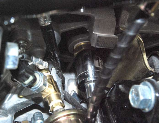
Here's the T fitting and adapters that I plan to use to connect both oil sensors and hopefully avoid any issues.

Broke the brass one off, didn't even feel like i tightened it that much, but now i'll have to order another one.....

It's a tight fit with the water sensor in there too and to try to make it tight and still have access to plug it in.

25th Anniversary Roadster #12 of 25
Gen 3 Coyote
TKO 600 mid-shift
Car
-
10-29-2019, 06:35 PM
#117
Senior Member
Got the engine in today with the help of some friends. Went pretty good, maybe took 30 mins once we started. Everything lined up good.


25th Anniversary Roadster #12 of 25
Gen 3 Coyote
TKO 600 mid-shift
Car
-
Post Thanks / Like - 1 Thanks, 5 Likes
-
10-30-2019, 04:25 PM
#118
Senior Member
With the engine in, I started installing some of the other things. Looks like there is plenty of room to work with the oil/water senders, as long as the headers are not in.
FYI: If you are doing the front battery mount from Breeze, it would be much easier to drill the holes before the engine is in. Doable after but was kinda a pain.
25th Anniversary Roadster #12 of 25
Gen 3 Coyote
TKO 600 mid-shift
Car
-
10-31-2019, 07:20 AM
#119
Senior Member

Delivery
Originally Posted by
delta0014
The car is here! #12 of 25
Delivery day was yesterday. Stewart showed up around noon. No issues unloading, driver was great.
Spent the rest of the day doing inventory (which sucked, but it's over for the most part) and removing the body. Inventory took awhile, some of the stuff is just not labeled well, although I could only find a few things that I'm missing that wasn't on the POL list.
Got the normal badging instead of the 25th anniversary badging...
The POL list was 3 pages long and includes most of the 25th stuff (seats, dash, brakes) and a lot of the bigger items.


This is exciting to see. Congratulations. I am expecting delivery of my 25th anniversary kit on about 11/21. I received brakes last week and put team together. I can't wait for when mine arrives. Good luck with the build.
-
Post Thanks / Like - 0 Thanks, 1 Likes
-
10-31-2019, 02:09 PM
#120
Senior Member
OK, time for questions.....
Hooked up the cold air intake and power steering.

Do I really have all this left over after hooking up the cold air?

Pulled the Coyote wiring harness, says to a 2 drill inch hole, but they give you a grommet for a much smaller hole.... Might have to see about doing something with this. I pulled it out and tried putting it in a smaller hole but the ends wouldn't even come close to fitting through the hole. Anyone get this?

Starter connections on the wiring harness has three connections and another one from the coyote harness. There's 2 big and 1 small connector on the starter... Which one goes where? The blue taped one is the one i'm suppose to cut.

Now to the fuel pressure regulator hookup. They gave me these three braided fuel hoses, but they are long. Is this really what connects the fuel pressure regulator to the fuel line that I ran up the passenger footboy? I assume the smaller one connects to the fuel rail on the engine. Am I missing something? I haven't hooked up the fuel tank/pump since I don't have them but I don't see anything in the instructions for using these.
And the vacuum hose line coming off the pressure regulator, where does that go?

25th Anniversary Roadster #12 of 25
Gen 3 Coyote
TKO 600 mid-shift
Car


 Thanks:
  Likes:


 Reply With Quote


