-
Senior Member

Connecting Vintage Tach to Coyote engine
Coyote with Vintage gauges
For connecting the Vintage gauge Tachometer to a Coyote engine the FF Roadster Coyote Engine installation instructions say to splice the purple COIL->TACH wire from the RF harness into the #4 cylinder coil plug wire.
Is there another ways to hook up the Tach other than tapping into the #4 cylinder coil plug wire as instructed?
Also, if tapping into the coil plug wire is necessary what type of connector is best to use to disconnect this wire if the engine needs to be pulled at any time in the future.
Again, thank you for any assistance.
Tim
Mk4 Complete Kit delivered 5/2019, Gen 2 Coyote, TKO 600, IRS, Wilwood F/R, Power steering, Halibrand 17 X 9 Front 17 X 10.5 Rear, Nitto NT555 G2 F/R
-
Senior Member

That's the only choice. You have to break into one of the coil-on-plug harnesses and tap the signal wire. It doesn't have to be #4. Can be any one of the eight. Pick the one that's most convenient for your wiring layout. You could add an in-line connector I guess if you wanted. I figured if that happened I'd just cut the wire and splice it back. Don't forget also you have to calibrate the tach to the ".5 pulse per rev" setting. Many forget that step and wonder why the tach doesn't work properly.
Be glad you didn't pick Autometer gauges. (Not that they aren't nice gauges...) It too requires you to break into the harness. But in a different location and also requires a $100+ tach adapter.
Build 1: Mk3 Roadster #5125. Sold 11/08/2014.
Build 2: Mk4 Roadster #7750. Sold 04/10/2017.
Build Thread
Build 3: Mk4 Roadster 20th Anniversary #8674. Sold 09/07/2020.
Build Thread and
Video.
Build 4: Gen 3 Type 65 Coupe #59. Gen 3 Coyote. Legal 03/04/2020.
Build Thread and
Video
Build 5: 35 Hot Rod Truck #138. LS3 and 4L65E auto. Rcvd 01/05/2021. Legal 04/20/2023.
Build Thread. Sold 11/9/2023.
-
Post Thanks / Like - 1 Thanks, 1 Likes
-
Senior Member

Originally Posted by
edwardb

That's the only choice. You have to break into one of the coil-on-plug harnesses and tap the signal wire. It doesn't have to be #4. Can be any one of the eight. Pick the one that's most convenient for your wiring layout. You could add an in-line connector I guess if you wanted. I figured if that happened I'd just cut the wire and splice it back. Don't forget also you have to calibrate the tach to the ".5 pulse per rev" setting. Many forget that step and wonder why the tach doesn't work properly.
Be glad you didn't pick Autometer gauges. (Not that they aren't nice gauges...) It too requires you to break into the harness. But in a different location and also requires a $100+ tach adapter.
Thanks for the feedback and confirmation. Always appreciated.
Mk4 Complete Kit delivered 5/2019, Gen 2 Coyote, TKO 600, IRS, Wilwood F/R, Power steering, Halibrand 17 X 9 Front 17 X 10.5 Rear, Nitto NT555 G2 F/R
-
Senior Member

Originally Posted by
edwardb
That's the only choice. You have to break into one of the coil-on-plug harnesses and tap the signal wire. It doesn't have to be #4. Can be any one of the eight. Pick the one that's most convenient for your wiring layout. You could add an in-line connector I guess if you wanted. I figured if that happened I'd just cut the wire and splice it back. Don't forget also you have to calibrate the tach to the ".5 pulse per rev" setting. Many forget that step and wonder why the tach doesn't work properly.
Be glad you didn't pick Autometer gauges. (Not that they aren't nice gauges...) It too requires you to break into the harness. But in a different location and also requires a $100+ tach adapter.
What is the best way to physically make the connection? Am replacing my FFR base AutoMeter tach & gauges with a SpeedHut Cobra 4" tach & gauges.
-
On a roll

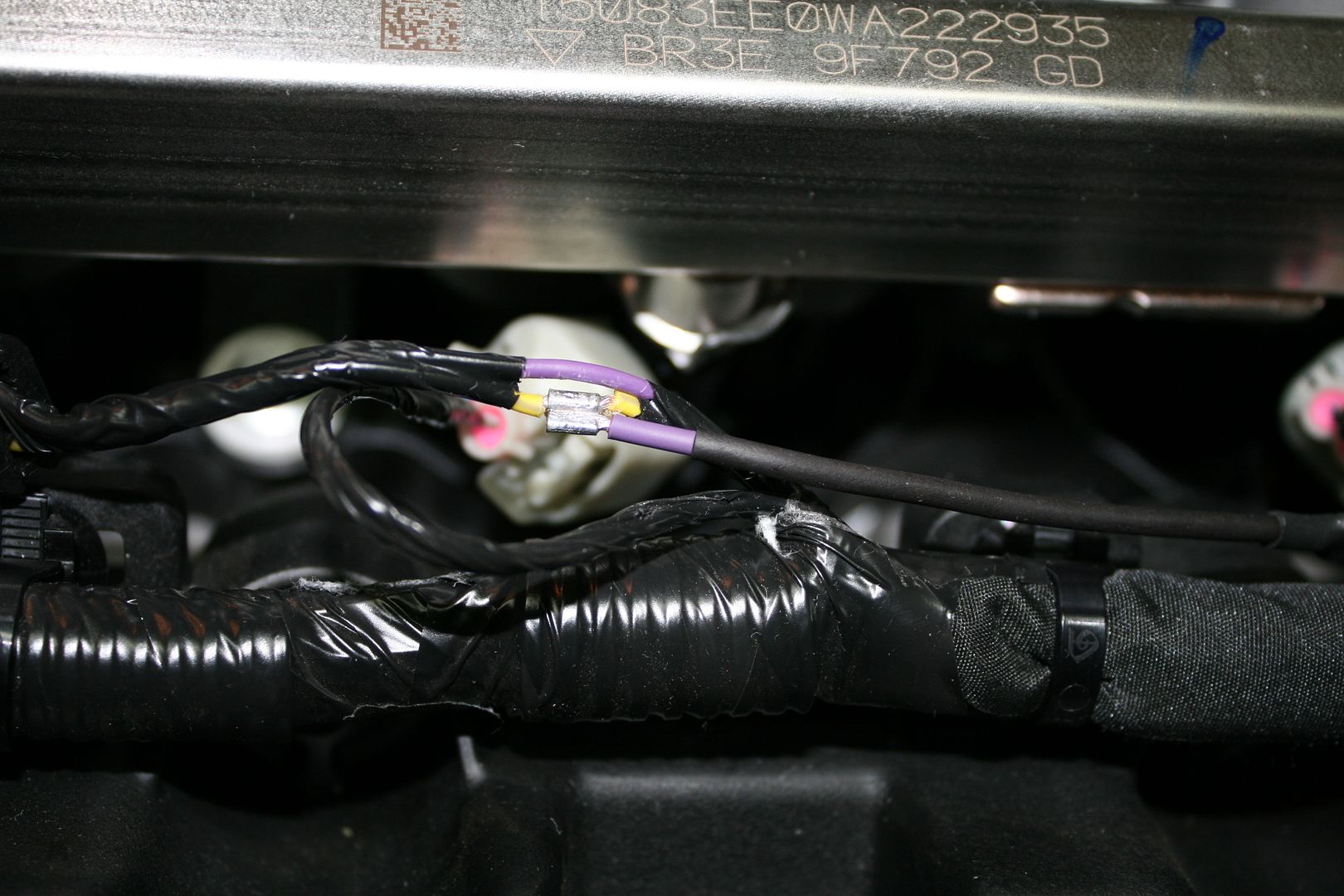
Here's one way:

I used a female spade connector. The engine wire is crimped into one of the "loops".
Mk IV Roadster - #8650 - delivered 7-17-2015 - first start 7-28-2018 - first go-kart 10-13-2018 - licensed and on the road 9-9-19: body/paint completed 3-17-2020.
Complete kit / 2015 Coyote / TKO600 / IRS / Wilwood brakes / Mid-Shift mod / Power Steering / Heater and Seat Heaters / RT turn signal / Breeze radiator shroud and mount
-
Post Thanks / Like - 1 Thanks, 0 Likes
-
Senior Member
Originally Posted by
BEAR-AvHistory
What is the best way to physically make the connection? Am replacing my FFR base AutoMeter tach & gauges with a SpeedHut Cobra 4" tach & gauges.
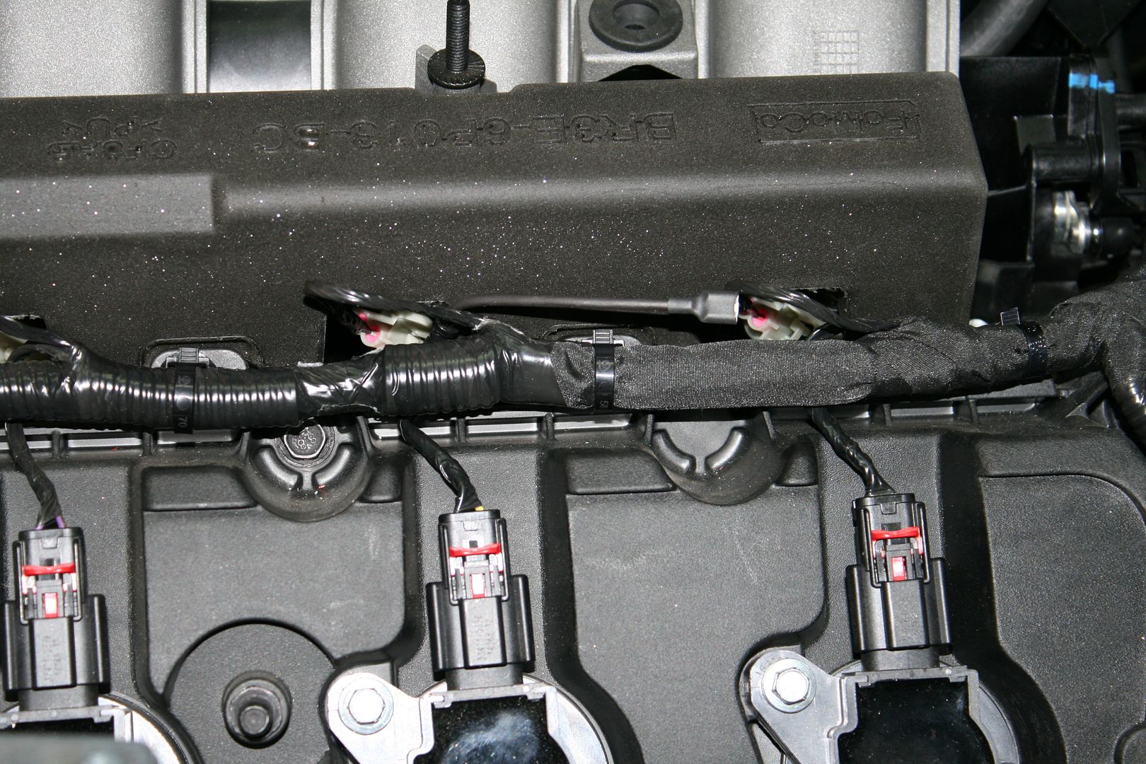
I carefully removed a section of insulation from the Coyote coil pack signal wire. Then wrapped the new wire several times around the exposed wire and lightly soldered. Then wrapped the splice with 3M 33 electrical tape. Then replaced the engine harness insulation with the new wire pulled back and routed through the firewall to the gauge.
Build 1: Mk3 Roadster #5125. Sold 11/08/2014.
Build 2: Mk4 Roadster #7750. Sold 04/10/2017.
Build Thread
Build 3: Mk4 Roadster 20th Anniversary #8674. Sold 09/07/2020.
Build Thread and
Video.
Build 4: Gen 3 Type 65 Coupe #59. Gen 3 Coyote. Legal 03/04/2020.
Build Thread and
Video
Build 5: 35 Hot Rod Truck #138. LS3 and 4L65E auto. Rcvd 01/05/2021. Legal 04/20/2023.
Build Thread. Sold 11/9/2023.
-
Senior Member

--
MKIV Roadster #8641
Complete Kit with IRS, Eaton Detroit Truetrac, 3.55 gears, Wilwood Brakes
Ford Racing Z427 w/ Pro-M Sequential Port EFI System
TKO 600 + McLeod Midshifter; Fast Freddie's Electro-Hydraulic power steering
Miller Customs Bodywork & Paint
-
Post Thanks / Like - 1 Thanks, 1 Likes
-
Senior Member
Last edited by edwardb; 04-12-2020 at 09:42 PM.
Build 1: Mk3 Roadster #5125. Sold 11/08/2014.
Build 2: Mk4 Roadster #7750. Sold 04/10/2017.
Build Thread
Build 3: Mk4 Roadster 20th Anniversary #8674. Sold 09/07/2020.
Build Thread and
Video.
Build 4: Gen 3 Type 65 Coupe #59. Gen 3 Coyote. Legal 03/04/2020.
Build Thread and
Video
Build 5: 35 Hot Rod Truck #138. LS3 and 4L65E auto. Rcvd 01/05/2021. Legal 04/20/2023.
Build Thread. Sold 11/9/2023.
-
Senior Member
Thanks all. That will set me up fine. 
-
Senior Member
Originally Posted by
edwardb
There isn't a lot of space. But that's an interesting approach. Might fit. Dug through my pictures and found I did my 20th Anniversary similar to what Al_C showed. On the Coupe (Gen 3 Coyote, which requires the same kind of connection) I just wrapped and soldered as I described before. Also, back to the OP, when looking at my pictures see that I did put a single spade connector on the wire so it could be removed in case of maintenance, engine removal, whatever. Memory fades after a couple years.
OK cool.. This is what I was planning on doing. Adding the spade lug. I plan on splicing by removing insulation, wrapping the wires, soldering then wrapping with electrical tape.
Thanks again
Tim
Mk4 Complete Kit delivered 5/2019, Gen 2 Coyote, TKO 600, IRS, Wilwood F/R, Power steering, Halibrand 17 X 9 Front 17 X 10.5 Rear, Nitto NT555 G2 F/R
-
Senior Member
Originally Posted by
edwardb
I carefully removed a section of insulation from the Coyote coil pack signal wire. Then wrapped the new wire several times around the exposed wire and lightly soldered. Then wrapped the splice with 3M 33 electrical tape. Then replaced the engine harness insulation with the new wire pulled back and routed through the firewall to the gauge.
I placed the Tach wire in with the Sensor harness leg coming through the fire wall. Will this be ok? Will the Tach wire put any electrical noise on the other sensor wires and cause any interference or problems?
Mk4 Complete Kit delivered 5/2019, Gen 2 Coyote, TKO 600, IRS, Wilwood F/R, Power steering, Halibrand 17 X 9 Front 17 X 10.5 Rear, Nitto NT555 G2 F/R
-
Senior Member
Originally Posted by
tbl100
I placed the Tach wire in with the Sensor harness leg coming through the fire wall. Will this be ok? Will the Tach wire put any electrical noise on the other sensor wires and cause any interference or problems?
Nope, that's fine. Did the same thing on both of my builds.
Build 1: Mk3 Roadster #5125. Sold 11/08/2014.
Build 2: Mk4 Roadster #7750. Sold 04/10/2017.
Build Thread
Build 3: Mk4 Roadster 20th Anniversary #8674. Sold 09/07/2020.
Build Thread and
Video.
Build 4: Gen 3 Type 65 Coupe #59. Gen 3 Coyote. Legal 03/04/2020.
Build Thread and
Video
Build 5: 35 Hot Rod Truck #138. LS3 and 4L65E auto. Rcvd 01/05/2021. Legal 04/20/2023.
Build Thread. Sold 11/9/2023.
-
Senior Member
Originally Posted by
edwardb
Nope, that's fine. Did the same thing on both of my builds.
ok great, Thanks
Mk4 Complete Kit delivered 5/2019, Gen 2 Coyote, TKO 600, IRS, Wilwood F/R, Power steering, Halibrand 17 X 9 Front 17 X 10.5 Rear, Nitto NT555 G2 F/R
-
Senior Member

OMG. My eyes hurt!
There are plenty of 2 into one PROPER connectors out there. Piggyback terminals, scotchlock (put the wires in and click), 3 way bullets. You can do it with a weatherpack. Or if you can solder, a 3 way splice.
-
Senior Member

SCOTCHLOCK, who the h-ll would use a scotchlock on an auto? Turn in your card.
Mrk III, 331 stroker, Borla stack injection, T5, 3:55 IRS, Power steering and brakes. Kleiner body & paint
-
Senior Member
Originally Posted by
Avalanche325
OMG. My eyes hurt!
There are plenty of 2 into one PROPER connectors out there. Piggyback terminals, scotchlock (put the wires in and click), 3 way bullets. You can do it with a weatherpack. Or if you can solder, a 3 way splice.
Look closely at the harness we're breaking into. It's about 1-1/2 inches long and has zero slack. It's also feeding one of the coil-on-plug modules, so obviously critical and you don't want to do anything to disturb that. Tapping a signal off to drive a tach is secondary. So peeling back a short section of insulation -- which doesn't disturb the primary wire -- and attaching the signal wire in as non-invasive way as possible is the primary goal. Any method that would cut the existing coil wire is out IMO. That rules out several of your suggestions. I'm not a fan of Scotchlok taps and haven't ever used them in my car builds. The Posi-Tap product karlos suggested is a possibility. Haven't seen that before. Otherwise, look away I guess. And definitely don't look at the Factory Five instructions.
Last edited by edwardb; 04-13-2020 at 08:57 PM.
Build 1: Mk3 Roadster #5125. Sold 11/08/2014.
Build 2: Mk4 Roadster #7750. Sold 04/10/2017.
Build Thread
Build 3: Mk4 Roadster 20th Anniversary #8674. Sold 09/07/2020.
Build Thread and
Video.
Build 4: Gen 3 Type 65 Coupe #59. Gen 3 Coyote. Legal 03/04/2020.
Build Thread and
Video
Build 5: 35 Hot Rod Truck #138. LS3 and 4L65E auto. Rcvd 01/05/2021. Legal 04/20/2023.
Build Thread. Sold 11/9/2023.
-
Post Thanks / Like - 0 Thanks, 2 Likes
-
Senior Member

Originally Posted by
edwardb
Look closely at the harness we're breaking into. It's about 1-1/2 inches long and has zero slack. It's also feeding one of the coil-on-plug modules, so obviously critical and you don't want to do anything to disturb that. Tapping a signal off to drive a tach is secondary. So peeling back a short section of insulation -- which doesn't disturb the primary wire -- and attaching the signal wire in as non-invasive way as possible is the primary goal. Any method that would cut the existing coil wire is out IMO. That rules out several of your suggestions. I'm not a fan of Scotchlok taps and haven't ever used them in my car builds. The Posi-Tap product karlos suggested is a possibility. Haven't seen that before. Otherwise, look away I guess. And definitely don't look at the Factory Five instructions.
Totally agree. This connection made me a little uncomfortable as the coil is important and the tach less so. I would never use a connector here as it adds weight and complexity to the coil wire. Carefully stripping back the insulation and soldering is the only way I think this should be done. It would have been nice if Ford were to supply the tach signal in a more accessible way, though.
Bradley
Build thread - Mk4, Coyote, IRS, Wilwood brakes, old-style soft top and accessories.
The distance between "finished" and finished is literally infinite.
-
Post Thanks / Like - 0 Thanks, 1 Likes
-
Senior Member
Originally Posted by
GTBradley
...It would have been nice if Ford were to supply the tach signal in a more accessible way, though.
Yeah, I certainly agree and have talked to a couple people at Ford Performance that I've gotten to know. I pointed out that the performance/hobby market they're selling these crate engines and control packs to are all going to have aftermarket tachs and sure would be nice to have a direct connection, like the Gen 1 control pack had. They agreed, but said there's nothing in the PCM/ODB2 for the Gen 2 and Gen 3 that is compatible with the "traditional" tach gauge feeds used by our aftermarket tachs. Which hasn't changed for decades since we pulled the signal off one side of the old style coils. Said we had no choice but to use a tach adapter, required with Autometer (and perhaps others) or go directly to a single coil on plug signal which fortunately the Speedhut gauges support.
Last edited by edwardb; 04-14-2020 at 04:09 PM.
Build 1: Mk3 Roadster #5125. Sold 11/08/2014.
Build 2: Mk4 Roadster #7750. Sold 04/10/2017.
Build Thread
Build 3: Mk4 Roadster 20th Anniversary #8674. Sold 09/07/2020.
Build Thread and
Video.
Build 4: Gen 3 Type 65 Coupe #59. Gen 3 Coyote. Legal 03/04/2020.
Build Thread and
Video
Build 5: 35 Hot Rod Truck #138. LS3 and 4L65E auto. Rcvd 01/05/2021. Legal 04/20/2023.
Build Thread. Sold 11/9/2023.
-
Post Thanks / Like - 0 Thanks, 2 Likes
-
Senior Member
Originally Posted by
rich grsc
SCOTCHLOCK, who the h-ll would use a scotchlock on an auto? Turn in your card.
Rated for automotive and marine. I guess you like the crimped spade lug better?
From 3M: - https://www.anixter.com/content/dam/...nectors-br.pdf
Choose from 35 different Scotchlok IDCs to
meet a variety of uses, including fluorescent ballast
installation and replacement, fixture and appliance wiring,
automotive and marine wiring and control circuit wiring.
There are specific ones just for automotive. 905 and 905N.
edwarb - exactly what these are good for is where you have no slack and you don't cut the main wire.
Last edited by Avalanche325; 04-14-2020 at 04:34 PM.
-
Senior Member
Originally Posted by
Avalanche325
edwarb - exactly what these are good for is where you have no slack and you don't cut the main wire.
Understand. Don't use 'em. Not saying it's right or wrong. We all have our own preferences and that's one of mine. The OP asked questions about how to hook up the tach wire and I showed him how I did it. He can go another way if he wants. His choice. I'm confident with what I did, but not everything will choose the same.
Build 1: Mk3 Roadster #5125. Sold 11/08/2014.
Build 2: Mk4 Roadster #7750. Sold 04/10/2017.
Build Thread
Build 3: Mk4 Roadster 20th Anniversary #8674. Sold 09/07/2020.
Build Thread and
Video.
Build 4: Gen 3 Type 65 Coupe #59. Gen 3 Coyote. Legal 03/04/2020.
Build Thread and
Video
Build 5: 35 Hot Rod Truck #138. LS3 and 4L65E auto. Rcvd 01/05/2021. Legal 04/20/2023.
Build Thread. Sold 11/9/2023.
-
Senior Member
I just wanted to show that there some connectors out there made for that type of thing, while poking a bit of fun. Some guys wouldn't know that some of these things exist.


 Thanks:
  Likes:


 Reply With Quote

