-
Senior Member

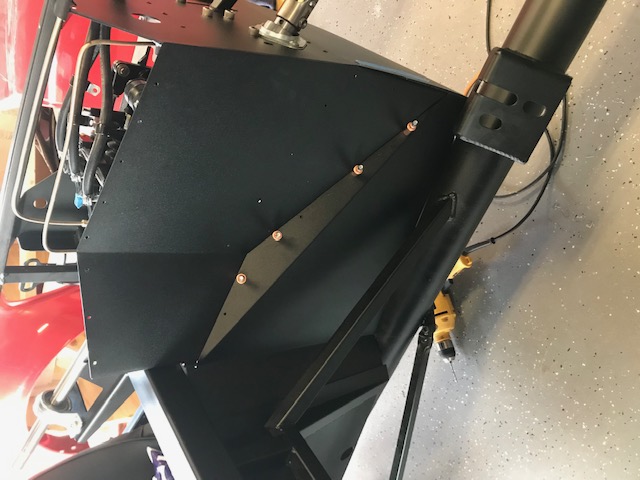
Some more progress to report today. My front lower control arms finally arrived, so I spent some quality time in the garage putting the IFS components together. Everything fit together reasonably well, with a few minor hiccups. The DS front bracket needed quite a bit of work with a spreading tool to get the lower control arm in place. The PS front bracket had the opposite situation – it actually had enough extra space to fit one of the spacers. Although the manual only says to use the spacers in the rear bracket, I assume it is OK to also use them to take space in the front brackets too, if necessary:


If I’m wrong about that, please let me know!
Anyway, here’s how everything looks now (not yet torqued to spec). Please let me know if you see anything wrong. I would not be at all surprised if I did something incorrectly.


I have not tightened anything to spec yet for two reasons. First, my torque wrench only goes up to 80 ft. lbs., nowhere near the 225-250 ft. lbs. needed for the wheel hubs. I was planning on borrowing/renting a big wrench from Auto Zone, but their lending program is apparently suspended because of COVID-19.
The other reason I’m waiting is that I’ve decided to install a power steering rack, and now I’m wondering if I need to trim a bit off the UCA adjusting sleeves. I know a number of threads have discussed this, e.g., https://thefactoryfiveforum.com/show...ter-amp-Camber. As a noobie, I’m really hesitant to take a hack saw to any portion of my front suspension, but I understand it will likely need to be done eventually because of the PS option. My question is: is it better to wait until I’ve actually done a rough alignment to figure out how much (if any) needs to be trimmed? Or go ahead and trim some off now, following the guidance of others who have already done it?
My next step is going to be the power steering rack, so we’ll see how that goes . . .
-
Post Thanks / Like - 0 Thanks, 1 Likes
-
Senior Member
Well, installing the power steering rack was an adventure, but I got it done! To bring the thread up to date, I decided to go with PS a few weeks ago while I was waiting for my LCA’s to arrive. Actually, I had originally wanted to do PS from the beginning, but I talked myself out of it when I ordered my complete kit because I thought it might add too much complexity to my build. Back then, I was trying to adhere to the KISS principle. But the more I researched it, the more I felt it was something I could probably handle.
I ordered an OEM replacement PS rack for a 1989 Mustang from Rock Auto. I also ordered Breeze offset solid aluminum bushings, which many on this forum have praised. I actually got a very nice call from Mark Reynolds from Breeze, who responded to a web query I posted about PS. It was nice of him to spend some time talking to me (a newbie) about how to install power steering on my Roadster.
Everything arrived in short order, and last night I began tackling the project. The first step was to remove the existing bushings, which was fairly easy with some taps of a hammer. The next step was to install the Breeze solid aluminum bushings. Some have said their Breeze bushings slipped in with ease, but mine did not. They were very snug, but I was able to get them in with a rubber mallet:

The next step was to test fit the rack on the frame. Like many have reported, I experienced some difficulty getting the passenger side bolt through the rear bracket. I did a lot of sanding with 100 grit sandpaper wrapped around a dowel, but I still could not get it through:

Eventually, I used a grinding tool to open up the hole enough to get the bolt through, and that worked fine.
The next step was to trim about 3/8 inch off the front rack mounting brackets (AKA rear LCA brackets) to avoid interference with the rubber boots. I used a Dremel cutting wheel and grinder to do this, then I primed and painted the exposed metal. I think it turned out OK:


Last edited by JB in NOVA; 05-13-2020 at 10:43 PM.
-
Senior Member
(Power Steering continued . . .)
I did have a “newbie moment” when I was trying to insert the tie rod ends into the steering arms on the spindles. At first, I could not figure out how this was going to happen given the misalignment of the tie rod end bolt versus the corresponding hole in the steering arm:

I’m sure almost everyone already knows the answer – the tie rod end bolt can swivel into position (which is why it has a zerk fitting and grease boot). But my newbie mind did not grasp that fact right away. So I immediately started wondering what I did wrong. Remembering something I’d read on Patrick’s 427 thread, I wondered whether I’d installed the steering arms on the wrong sides. Sure enough . . . I had. The tapers were pointing the wrong way.
Warning to other first-timers like me: the FFR instructions are somewhat vague on this point. Page 47 of the manual says: “Bolt the steering arms to the spindles so the tie rod end will mount from the bottom.” What it doesn’t tell you is that the steering arm bolt holes are tapered, and you have to put the wide end of the taper down, “so the tie rod end will mount from the bottom.” Effectively, this means there is a right and a left steering arm, and it’s easy to get them switched. There’s a good discussion here: https://thefactoryfiveforum.com/show...per#post361644 (see posts # 91-95).
Of course, even after I switched the arms, I still had the “misalignment” picture above. That’s when I finally realized (Homer Simpson “Doh!”) that the tie rod end bolts can swivel. Problem solved, and finally my power steering rack was fully installed (except for torqueing to spec):

The rubber boots just barely clear the ground-down LCA brackets:


I hope that’s OK because I really don’t want to remove any more metal from those brackets, which support the lower control arms.
As always, if anyone sees anything wrong with my power steering installation, I would be very grateful for your input.
Last edited by JB in NOVA; 05-16-2020 at 11:27 PM.
-
Post Thanks / Like - 1 Thanks, 1 Likes
-
Senior Member

Hi JB, I almost asked you a couple of days ago to make sure you had installed the steering arms correctly but I see you do now. I did the same thing and thanks to this forum it was pointed out and I got it corrected. Did you get the fittings for mounting the hoses to the rack from Mark? I got them and stainless braided line and the -6 AN fittings from him and made up the lines myself after watching a few youtube videos on making up AN fittings. Keep up the good work.
JR
Mk4 complete kit #9059 ordered 1/19/17 delivered 3/23/17, 2015 IRS, Fortes/DART347,TKO 600, hyd clutch, P/S, 12.88 wilwood brakes front and rear, heater/defrost and vintage gauges
First start and go-cart 4/11/18. Taken To Whitby Motorcars Greensboro, N.C. 2/5/21 for body/paint
-
Post Thanks / Like - 0 Thanks, 1 Likes
-
Senior Member

Originally Posted by
jrcuz

Hi JB, I almost asked you a couple of days ago to make sure you had installed the steering arms correctly but I see you do now. I did the same thing and thanks to this forum it was pointed out and I got it corrected. Did you get the fittings for mounting the hoses to the rack from Mark? I got them and stainless braided line and the -6 AN fittings from him and made up the lines myself after watching a few youtube videos on making up AN fittings. Keep up the good work.
JR
Ha! Thanks, JR. I think it's a hidden trap in the FFR instructions just to trip up newbies like me. But thanks to the forum, I figured it out -- no harm, no foul. I think I'll do the same as you and order all the fittings from Breeze and go with stainless braided lines.
-
Senior Member
JB, I'm very pleased with my stainless braided lines if I do say so myself. If you do use AN fittings be warned they do cross thread very easily. I had to get 1 additional fitting from Breeze. Do you have any idea of what p/s pump you will use? Mine is a KRC that Mike Forte put on my eng. I ordered more braided line from Breeze than I needed so had some left over and in my application I used 2 straight fittings and 2 90 degree fittings. Hopefully this COVID-19 will pass soon and you can maybe come and see my build and I can lend you some tools for cutting the stainless line and testing the completed lines for leaks. Also I have the EASTWOOD flaring tool for doing brake line flares Tony has it now. This got longer than I expected so I'll get off now.
JR
Mk4 complete kit #9059 ordered 1/19/17 delivered 3/23/17, 2015 IRS, Fortes/DART347,TKO 600, hyd clutch, P/S, 12.88 wilwood brakes front and rear, heater/defrost and vintage gauges
First start and go-cart 4/11/18. Taken To Whitby Motorcars Greensboro, N.C. 2/5/21 for body/paint
-
Post Thanks / Like - 1 Thanks, 0 Likes
-
Senior Member
So I’m continuing to make progress . . . slowly but surely. I spent a few hours today finishing the front suspension. With everything fastened but not torqued to spec, I attempted to adjust the upper control arms to match the rough alignment recommended in the manual for power steering (high caster):

As many others have reported in this forum, I was not able to get the rear arm adjusted down to 7.375 inches, measured from the center of the pivot bolt to the center of the ball joint. On the passenger’s side, I could only get to 7.75 inches (although there was probably still another ¼ inch of thread left to play with if I re-centered the adjustment sleeve). On the driver’s side, I could only get to 7.4375 inches:


Based on the recommendation of others on this forum, I decided to trim the rear adjustment sleeves to allow more leeway for this alignment. I used a hacksaw to trim about 3/8 inches from one end of each sleeve, and a Dremel sanding tool to clean up the cut:


I used a Dremel cutting wheel to cut the bolts the same amount. On the PS, I found I needed to cut both bolts about 3/8 inches. Once I did this, I was able to get both UCAs into the recommended rough alignment for power steering.
After this, there was just one last thing I needed to get everything in the front suspension torqued to spec. Having struck out trying to rent a large torque wrench from Auto Zone, Sun Belt Rentals, etc., I finally gave in and bought a big-azz torque wrench and a 36mm socket for the hub nuts. With these, I was able to get the hub nuts torqued to 225-250 ft-lbs without too much trouble at all:

It’s amazing what a long lever arm can do! I now have a fully assembled and properly torqued front suspension.
-
Post Thanks / Like - 0 Thanks, 2 Likes
-
Senior Member
The other thing I managed to complete is the bracket for my triple brake/clutch reservoir:

I won’t be going into the bracket-making business anytime soon, but I was happy with the result given that I have no experience working with metal. I formed the bracket from 16-guage plate steel (Home Depot), and I used some angle stock (Home Depot) and my bench vise as a makeshift sheet-metal brake. I watched some Youtube videos to figure out how to do it. I cut a groove on the inside of the bend to reduce the bend radius. I used a template to drill the mounting holes (this was the hardest part – It was amazingly difficult to get everything to line up, even with a template – I suspect drilling drift was the culprit). Finally, I sanded, primed, and painted the bracket. Here’s the result:

Last edited by JB in NOVA; 05-16-2020 at 11:31 PM.
-
Post Thanks / Like - 0 Thanks, 2 Likes
-
Senior Member
Today I installed the front rotors and brakes:

I also attempted to center the power steering rack using the Breeze offset bushings. Per the Breeze instructions, I used a carpenter’s square to measure from the tip of each tie rod to a reference point on the frame with the rack rotated hard left and hard right. I was relieved to see I was only 1/16” off from center. I used two ¼” flathead screwdrivers, per the Breeze instructions, to try to rotate the bushings a tiny bit toward the driver’s side. Because my bushings had gone in very tight, I was wondering whether this would make centering the rack difficult. The answer is YES! Unless I’m missing some magic technique, there is no way those bushings are going to rotate using two screwdrivers. And I was getting kind of nervous putting that much muscle into it while I was lying underneath the car on jacks. So, for now, I’m going to have to live with the 1/16” offset unless I figure out some other way to correct it.
On that note, I carefully centered the rack at 1.5 turns (it came with helpful center markings) and made sure the wheels were both straight by measuring the front and back of the rotors from the frame with a carpenter’s square. In that configuration, there were approximately 3 “threads” of difference between the right and left tie rod ends. In other words, the left tie rod end had to screw in 3 extra revolutions compared to the right tie rod end to mate with the steering arms. To me (a newbie), that seems like it should be OK, but I would appreciate any different opinions others may have. Here’s the assembled front end, with the power steering rack still only wrench tight (in case I need further adjustments).

If anyone sees anything wrong with my setup, or has some advice about how to make the Breeze offset bushings rotate despite being tightly inserted into the housings, I would really appreciate it.
Last edited by JB in NOVA; 05-17-2020 at 06:11 AM.
-
Senior Member
Next I moved on to the steering assembly. Everything was going perfectly . . . almost TOO perfectly, until I got to the final step of inserting the upper steering shaft into the lower steering shaft. The two were close, but not close enough, and I did not want to force them together:

I was sure I was in for hours of frustration and searching the forum for answers, but first I decided to loosen all the set screws and fittings to see if I could isolate the problem. Once everything was loosened, the whole setup seemed to slip into place nicely. I’m not sure what the culprit was, but the lesson I learned was don’t tighten the set crews until the whole steering assembly is in place. I suppose this is just common sense, but it took me a “newbie iteration” to figure it out.
Once I did this, everything aligned very nicely, and I now have smooth movement from hard left to hard right with no binding or interference.

I tightened everything down, except I have not yet pushed the upper steering shaft all the way into the lower steering shaft, since that seems like a fairly permanent interference fit. Before I do that, I wanted to make sure there are no obvious problems with my steering setup. If anyone sees any problems, please let me know.
I do want to confirm one other thing with the forum. The FFR manual says: “Use thread locker on all the steering shaft screws that do not have jam nuts and the adapter screws.” (p. 152). As far as I can tell, the only screws that meet this definition are the set screws before and after the flange bearing:


Are there any other screws that require thread blocker? And what are the “adapter screws”? I don’t see anything in this section of the manual described as “adapter screws.” I just want to make sure I’m not missing something.
[As an aside, I don't love having "CHINA" stamped on any part of my steering assembly. But I guess it is what it is . . .]
-
Post Thanks / Like - 0 Thanks, 1 Likes
-
Senior Member
JB good progress. I'm with you on the China thing seems like everything I touch anymore has China on it. I spent several hours yesterday putting in heat/sound matting in the cockpit only got the rear bulkhead finished, maybe more today.
JR
Mk4 complete kit #9059 ordered 1/19/17 delivered 3/23/17, 2015 IRS, Fortes/DART347,TKO 600, hyd clutch, P/S, 12.88 wilwood brakes front and rear, heater/defrost and vintage gauges
First start and go-cart 4/11/18. Taken To Whitby Motorcars Greensboro, N.C. 2/5/21 for body/paint
-
Post Thanks / Like - 0 Thanks, 1 Likes
-
Senior Member
Still chipping away at the project, slowly but surely. It’s been nice having my son home helping me with the Roadster project for the past few days. Unfortunately, he was furloughed by his company up in PA due to COVID-19 (they say temporarily . . . but we’ll see). Regardless, he always has a home here.
The last couple days have been focused on the fuel tank. By way of background, I am using the FFR in-tank fuel pump/EFI option. So, I followed the Mk4 manual for the basic tank install and the more specific pump/hanger instructions that came with the FFR in-tank pump/EFI kit.
The fuel pump instructions were relatively clear, EXCEPT for the seemingly simple task of “3) install the lead wires onto the pump terminals.” That one step – deceptively easy as it sounds – ended up taking me well over an hour and a few choice words to complete. There are two wires for the in-tank pump: red and black. Each has a different sized connector—the red connector is clearly larger than the black connector. This would be a no-brainer if the terminals in the pump were similarly differentiated in size. But the terminals appear to be the same size (although it is difficult to tell because they are recessed within a housing). To be fair, I use reading glasses, so this might be clearer to others, but it was not to me. The red connector easily slips onto either terminal, but the black connector doesn’t “easily” fit onto either terminal. The instructions say nothing about this, except to warn about “making sure that proper polarity is maintained.” Gee, thanks.
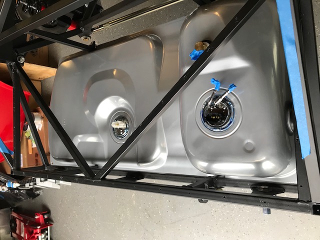
Long story short, I was finally able to discern that one terminal is slightly narrower than the other (I think). And after many attempts, I was able to coax the black connector onto what is hopefully the narrower of the two terminals. I note that Patrick’s 427 thread reported a similar problem with these connectors: https://thefactoryfiveforum.com/show...27-Build/page4 (see posts 131-136). Only time will tell whether I got it right. With that frustrating step completed, I was able to get the pump and hanger assembled and everything installed in the tank without any further problems:

Next I lifted the tank in place for mounting:

As many on this forum have reported, the PS fuel tank strap is a bear to get into place. I bent the tank flange down at the strap locations, as recommended, which helped get the DS strap in place, but I was still about half an inch away from getting the PS strap within “bolt range.” So rather than fight a losing battle with a bolt that is basically too short, I opted to do what others on this forum have suggested: I bought longer bolts. I went with 5/8” x 3” stainless-steel bolts:


I assume this is OK. It certainly made installation a lot easier because the nut could make engagement at a lower angle yet still tighten up to where it would have been with the FFR-supplied 2” bolts. But if anyone thinks this is ill-advised for some reason, please let me know. I realize there can be hidden issues that might not be apparent during the install phase, so I am very wary about each deviation from the FFR instructions. But this one seemed like a no-brainer.
Anyway, I got the tank installed, and I think it looks good:

Next I’ll be tackling the fuel lines and the other components of the fuel delivery/return system . . .
Last edited by JB in NOVA; 05-18-2020 at 11:22 PM.
-
Post Thanks / Like - 0 Thanks, 1 Likes
-
Looks great, following your build and keep posting the pictures for reference. in the stage of fitting and drilling panels.
-
Post Thanks / Like - 0 Thanks, 1 Likes
-
Senior Member

Originally Posted by
jrcuz
JB, I'm very pleased with my stainless braided lines if I do say so myself. If you do use AN fittings be warned they do cross thread very easily. I had to get 1 additional fitting from Breeze. Do you have any idea of what p/s pump you will use? Mine is a KRC that Mike Forte put on my eng. I ordered more braided line from Breeze than I needed so had some left over and in my application I used 2 straight fittings and 2 90 degree fittings. Hopefully this COVID-19 will pass soon and you can maybe come and see my build and I can lend you some tools for cutting the stainless line and testing the completed lines for leaks. Also I have the EASTWOOD flaring tool for doing brake line flares Tony has it now. This got longer than I expected so I'll get off now.
JR
That Eastwood professional flaring tool is great. JB/JR happy to pass it along.
JR, getting ready to cut and fix up my braided fuel lines. Sending you a PM.
MKIV Complete Kit #9494 l Delivered 1/5/19 l First Start
11/28/20 l First Go-kart
4/11/21 l Carb'd 347 l Mid-shift TKO600 l 3.55 IRS l P/S l Forte Mechanical Throttle Linkage l RT Turn Signal, Drop Trunk l Breeze Upper/Lower Radiator Support, Fan Shroud l Boig Upper/Lower Cool Tubes & Quiet Pipes l 18" FFR Gasser Wheels l
Build Thread
-
Senior Member
Originally Posted by
VAHokie
That Eastwood professional flaring tool is great. JB/JR happy to pass it along.
Thanks! I might take you up on that. At least I'll have a good answer for my wife when she asks, "you bought another tool?"
-
Senior Member
Hi JB, when Tony passes the Eastwood flaring tool to you I would suggest you watch the video for using it on the Eastwood site it helped me a lot.
JR
Mk4 complete kit #9059 ordered 1/19/17 delivered 3/23/17, 2015 IRS, Fortes/DART347,TKO 600, hyd clutch, P/S, 12.88 wilwood brakes front and rear, heater/defrost and vintage gauges
First start and go-cart 4/11/18. Taken To Whitby Motorcars Greensboro, N.C. 2/5/21 for body/paint
-
Post Thanks / Like - 1 Thanks, 0 Likes
-
Senior Member
Real work has been keeping me busy, so not a lot of progress to report. I decided to mock-up my EFI/fuel delivery system, just to make sure I understand all the fittings and have a reasonable plan for placement of the components. Almost immediately, I ran into a “newbie roadblock” when I went to mock-up the send line from the tank to the fuel filter.
The FFR EFI kit instructions (https://www.factoryfive.com/wp-conte...l-system-1.pdf) say: “Use the 5/16” hose and hose clamps from the kit along with the 5/16” fuel line connector from the EFI components and 3/8” to 5/16” fuel line connector from the OEM fuel tank components to run the fuel line from the fuel tank to the fuel filter.”
Being short of attention span, my brain immediately went to the prefabricated assembly that the MK4 kit provides for the tank-to-filter connection, which is described at p. 186 of the FFR manual. It looks like this:

This assembly has 3/8” quick-disconnects on each end, but a 3/8” quick connect will not fit the 5/16” fuel tank sender line in the EFI setup. And I could not see any easy way to replace that connection in this pre-fab assembly with the 5/16 to 3/8 connector provided in the EFI kit. My brain just did not grasp that there could be another 5/16” hose in the Mk4 kit for the tank-to-filter connection, since this pre-fab assembly already seemed to serve that purpose. (Spoiler alert: I was wrong).
I sheepishly sent Dave at FFR an email, explaining my confusion. He responded quickly (and graciously), informing me that I’m supposed to use the #14504 connector from the OEM fuel tank components, #80281 connector from the EFI fuel system and #16914 5/16” hose and #11138 clamps from #14652 fuel line components to make the hose whatever length I require.
Yep, those parts were all in the kits as described. Thanks Dave! With that hiccup behind me, I was able to complete my mock-up. I would be very grateful if someone could let me know if this plan looks acceptable. Starting from the fuel tank sender (I will shorten this line appropriately):

I plan to mount the fuel filter on the cross bar in front of the trunk area:
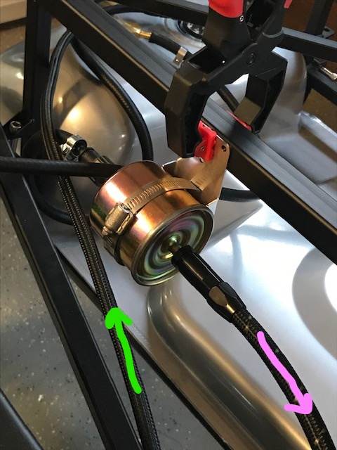
I plan to run the supply and return lines over the axle, around the corner, and down the left side of the transmission tunnel:


Finally, I plan to mount the fuel pressure regulator on the left side of the firewall, down low, near the DS footbox. (I wanted to mount on the right side to keep all fuel on that side, but I’m afraid I won’t have room after I mount my heater). Ignore the temporary hanger – I just used it mock-up the regulator at the desired height.

So that’s the plan. If anyone sees any problems with this plan (accessibility, interference, sheer stupidity, etc.) please let me know. I really value the wisdom of this forum.
Last edited by JB in NOVA; 05-20-2020 at 08:35 PM.
-
Post Thanks / Like - 0 Thanks, 1 Likes
-
Make sure you can get to the fuel filter after the alum, suspension and body are on the car. Then make sure the clamp screw head is accessible and not on the back side of the filter.
My F5 black quick disconnects leaked. Depending on where you use them, you may want to run the pump and check for leaks, easily accessible.
20th Anniversary Mk IV, A50XS Coyote, TKO 600, Trunk Drop Box, Trunk Battery Box, Cubby Hole, Seat Heaters, Radiator hanger and shroud.
-
Senior Member

Hi JB,
Most builds keep the fuel lines on the outside of the passenger side 4" side tube. What you have will probably work but I do know that for accessibility, avoiding heat build up and visual inspection it's best to keep fuel lines elsewhere.
Just my .02
Mk IV Roadster #9749, Kit received Jan 2, 2020, Blueprint SBF 347 TKO600 Holley Sniper EFI, Dual roll bars, IRS, 17" Halibrand, Nitto 555 G2 245, 315 Road legal Oct 20, 2020
-
Post Thanks / Like - 1 Thanks, 0 Likes
-
I have seen lots of heated discussion about this. Most of the experienced builders would discourage running the fuel lines through the transmission tunnel. I think its a safety issue. As Caddy Dad said the rec is to run them outside the passenger side 4", further, most also recommend using hard lines when underneath the car, however, I'm pretty sure high quality braided will be just fine.
-
Post Thanks / Like - 1 Thanks, 0 Likes
-
Senior Member
Thanks for the comments, everyone! I'm currently rethinking my entire fuel system. In addition to the excellent comments you have provided, I also realized that I don't need an external regulator at all. I confirmed with Blueprint that the sniper EFI on the engine I ordered will self-regulate. So I'll be adding the external regulator to the growing pile of FFR components that I've purchased but will not be using. I plan to run hard lines along the outside of the PS 4" tube, as recommended.
-
Post Thanks / Like - 0 Thanks, 1 Likes
-
Originally Posted by
JB in NOVA
Thanks for the comments, everyone! I'm currently rethinking my entire fuel system. In addition to the excellent comments you have provided, I also realized that I don't need an external regulator at all. I confirmed with Blueprint that the sniper EFI on the engine I ordered will self-regulate. So I'll be adding the external regulator to the growing pile of FFR components that I've purchased but will not be using. I plan to run hard lines along the outside of the PS 4" tube, as recommended.
Food for thought...the Sniper internal regulator is prone to failure so some folks remove it and use an external. Since you've got it, that's an option.
-
Post Thanks / Like - 1 Thanks, 1 Likes
-
Senior Member
After a few days off to enjoy the Memorial Day weekend, I got back to the Roadster project today. I think I’ve finally got my fuel system figured out, but it will involve some additional components, so I’m going to put that aside for a while. I decided to move on to the brake system.
The first thing I had to decide is how to route my three reservoir lines through the DS footbox front wall. I found some great suggestions in this thread: https://thefactoryfiveforum.com/show...rough-firewall Of those, the one I liked best was Straversi’s setup, where he routed all three hoses through the unused manual-clutch opening using a custom cover with grommets. I’m not sure how he did his, but I found the hole is not quite big enough to squeeze in three full grommets. After some experimentation, I was able to make something similar to his, although maybe not as pretty.
First, I fabricated this Mickey Mouse looking thing:

I smoothed out all the sharp edges with a Dremel. After priming and painting, I cut three rubber grommets into arcs to cover all the inside edges:

Here’s the final result:

I like this approach because it re-purposes a hole I would have had to cover anyway. Finally, I hooked up the hoses to the master cylinders inside the footbox (the green wire is my mock-up for the front brake line):

I also installed the flexible lines to the front brakes:


Next I’ll be trying my hand at installing hard brake lines. I’m sure that will be interesting . . .
-
Post Thanks / Like - 0 Thanks, 2 Likes
-
Senior Member
-
Senior Member
Rear Brake Hard Lines
For the rear brakes, I know a lot of people run a line from the MC down the inside front corner of the DS footbox and out the bottom to the 4” tube. But for a variety of reasons (including my lack of confidence that I won’t someday have a leak), I decided to keep the brake lines entirely out of the cockpit. I also did not like the routing recommended in the manual, i.e., down the outside front of the DS footbox. Kind of unsightly.
I saw on the "other" forum that a few people have routed their rear brake line forward and then down to the 4” tube near the front control arms. Does anyone have any experience with this approach? I know it will add length to the rear brake line run, but since I’m using coiled NiCopp, I’m not quite as worried about that. Anyway, for the time being, this is what I’ve mocked up for the long rear brake line run. From the inside master cylinder:

Through the slot in the front DS footbox panel to the lower ¾” frame rail:

Along the lower rail, beneath the T-connection for the front brakes, to the vertical frame rail near the control arms:

From there, I plan to do an in-line connection to a long tube that goes all the way back to the left rear brake T-connection. I’ve mocked it up, but I’m waiting for some gravel guard that I ordered before I complete this connection:

In the meantime, I would be grateful for any comments or constructive criticism about my proposed rear brake line routing. If there is something ill-advised about it, the only thing I'm out right now is about $20 worth of NiCopp tubing. I'd rather know about potential problems now, rather than "down the road." Thanks!
-
Senior Member
Hi JB, everything looks pretty good. One thing I did was any place I had a brake line going through an aluminum panel I used a short piece of of small I.D. rubber hose to protect the line. I secured the hose with zip ties.
JR
Mk4 complete kit #9059 ordered 1/19/17 delivered 3/23/17, 2015 IRS, Fortes/DART347,TKO 600, hyd clutch, P/S, 12.88 wilwood brakes front and rear, heater/defrost and vintage gauges
First start and go-cart 4/11/18. Taken To Whitby Motorcars Greensboro, N.C. 2/5/21 for body/paint
-
Post Thanks / Like - 1 Thanks, 0 Likes
-
Senior Member
Originally Posted by
JB in NOVA
I tightened everything down, except I have not yet pushed the upper steering shaft all the way into the lower steering shaft, since that seems like a fairly permanent interference fit. Before I do that, I wanted to make sure there are no obvious problems with my steering setup. If anyone sees any problems, please let me know.
I'm still waiting for my gravel guard from Inline Tube to finish up the brake lines, but in the meantime I did resolve this issue with the upper steering shaft. As I explained earlier, the upper shaft did not want to slide into the lower shaft (without brute force), and I did not want to force it. After checking with FFR to make sure it was OK to sand it down, thats what I did. It took quite a bit of sanding of the upper shaft, as well as sanding inside the lower shaft to remove what felt like a small burr. I finished with 150 grit sandpaper and then a Scotch-Brite pad, then I coated everything with machine oil. After that, I was able to get the upper shaft to slide in fairly easily. With the spring washers in place, it took some light tapping with a rubber mallet, but everything snugged up very nicely:

My goal for this weekend is to finish the brake lines and fill and bleed the system. I'm looking forward to this step, but I must admit I'm nervous. I've never bled brakes in my life. After a lot of reading on the forum and watching several Youtube videos, my current plan is to (1) gravity fill the system by filling the reservoirs with the caliper bleed valves open and adding fluid until I get flow (or at least drips) from all four bleed valves; and (2) working with both front and rear brakes on each side at the same time, bleed the lines by pumping the brake pedal. I am hoping to be able to prime the master cylinders using this technique: https://www.youtube.com/watch?v=HBYaV7nOynE (multiple small 1/2" pumps of the brake pedal). Then I plan to use this technique to feed the bleed lines back into the reservoirs to create a "closed system" during the bleed process: https://www.youtube.com/watch?v=oi4BnNA3Ep4
If anyone thinks that's a bad plan, please let me know. If that plan fails, I will move on to one of the other techniques discussed in the forum, such as pressure bleeding. But I'd like to try something simple first.
Last edited by JB in NOVA; 06-03-2020 at 07:21 PM.
-
I used the same method without issue. I have the Wilwood master cyl and brake calipers.
I opened all the top bleeders and kept working on something else. Soon I had a drip from one then all.
With the help of someone, we bleed all corners and never looked back.
Not for sure I understand working on 2 brakes at the same time.
Bleed the brake, farthest from the master cylinder, individually.
I did not bleed the master cylinders prior to bleeding the system. Filled the reservoirs and let gravity work, until you get ready to pump the pedal.
Probably not necessary to say, sounds like you have done your homework, but pump slow.
2 very important items, master cyl push rods must be loose, keep reservoirs topped off.
Last edited by Railroad; 06-04-2020 at 08:59 AM.
20th Anniversary Mk IV, A50XS Coyote, TKO 600, Trunk Drop Box, Trunk Battery Box, Cubby Hole, Seat Heaters, Radiator hanger and shroud.
-
Senior Member
Railroad, thanks for the confirmation. Good to know the simple method works. Regarding this comment:
Originally Posted by
Railroad
Not for sure I understand working on 2 brakes at the same time.
Not sure I completely understand it, either. From what I can tell from various comments, the balance bar can sometimes cause problems if you try to bleed one wheel at a time. But again, I'm not in a position to answer the question of why . . . or even if it's actually true. I'm just a newbie reading forum posts and hoping to get it right the first time.
-
Senior Member
Well, another rookie mistake to report. Because I’m preparing to fill and bleed the brake system, I decided to go back through each step of the instructions that I followed and take a new look with fresh eyes. When I re-read the instructions for the 11.65” rear brakes, I realized I had installed them on the wrong sides (i.e., upside down).
The instructions say: “When installing the caliper make sure that the brake fluid bleed screw is on the top side of the caliper.” When I originally read this instruction several weeks ago, I misinterpreted it to mean ensure the bleed screw is on the top side of the rotor, which of course it will always be because of how the caliper is positioned on the rotor. But when I thought about this more, I realized my rear brakes were upside down. I had the bleed valve on the bottom half of the caliper (i.e., below the silver coil), instead of on the top half of the caliper. You can see this from my old post:
Originally Posted by
JB in NOVA
Here’s how they look:


Easy enough to fix by swapping the rear calipers so the bleed valve is above the silver coil.

Actually, I’m glad I caught this mistake for more reasons than one. Once I got the calipers on the correct sides, the inside edges of the calipers were even closer to the rotor than they were before – something I was already concerned about. That’s when I re-read the instructions and figured out how to solve this problem.
The instructions say: “Make sure the caliper bracket is centered over the rotor then check to see if a spacer is needed between the caliper bracket and the caliper mount or between the two brackets.” Doh! I honestly don’t know how I overlooked that last little bit before. I removed the outer caliper bracket on each side, installed a washer between the two mounting brackets on each of the four mounting bolts, and now the rotors are very nicely centered in the calipers:


The axle turns much easier now, and I feel much better about the whole rear brake set up. Whew! It’s amazing how easy it is to miss little things that are right there in the instructions. It's like you see them, but you don't "see" them.
As always, if anyone sees anything wrong with my setup, please let me know.
-
Post Thanks / Like - 0 Thanks, 1 Likes
-
Good job. I had an old guy, once tell me, if you catch it yourself, it is not an error.
Might put a rag or something under each brake, while waiting on the gravity feed drip. Do not want to mess up that nice floor finish.
20th Anniversary Mk IV, A50XS Coyote, TKO 600, Trunk Drop Box, Trunk Battery Box, Cubby Hole, Seat Heaters, Radiator hanger and shroud.
-
Post Thanks / Like - 0 Thanks, 1 Likes
-
I do not know if this will apply to your build,,,,, on the steering shaft pillar bearing,,,,I had to put 2 or 3 washers under each side. As I rotated the steering wheel, I could feel the joints go through a notch feeling. I think my foot box support bearing is mounted on the outside of the foot box.
If your steering wheel turns without change in the resistance, please ignore.
20th Anniversary Mk IV, A50XS Coyote, TKO 600, Trunk Drop Box, Trunk Battery Box, Cubby Hole, Seat Heaters, Radiator hanger and shroud.
-
Senior Member
Brake Line Finishing Touches
I spent the last few days finishing up the brake system, and I think I’m finally done! First, I took care of some odds and ends with the brake lines themselves.
For the run from the MC to the front left front brake along the top frame rail, I was worried about having the brake line flush against the rail because I thought it might interfere with the body when installed. From what I can tell, the fiberglass body rests on top of and along the inside edge of the top rail in the engine compartment. To avoid any interference, I made a couple brackets to push the brake line away from the rail:

I widened the notch in the front footbox wall where the front brake line passes through. For now, I’m using some tubing to protect the brake line in that area. I’ll probably cut a longer piece and zip tie on either end, as jrcuz suggested.

I fashioned a pass-through plate to block off the horizontal slot in the front footbox wall where I brought the rear brake line forward along the lower rail:

Finally, I installed stainless steel gravel guard on the long run along the 4” tube and up toward the rear T-junction:


I know some folks have said gravel guard traps salt and grime and could do more harm than good. But since I’m using NiCopp, which is corrosion resistant, I’m not quite as worried about that. And having the gravel guard gives me peace of mind that something won’t jump up and dent the soft NiCopp line on the bottom of the car.
With all the brake lines installed and tightened down, I was ready to fill and bleed the system . . .
-
Post Thanks / Like - 0 Thanks, 1 Likes
-
Senior Member
Brake System Fill and Bleed
My original plan was to gravity feed the system, but I quickly realized that wouldn’t work because I have a portion of the front brake lines that is almost level with the top of the reservoirs. I filled the reservoirs and allowed them to fill the master cylinders. Immediately, I had leaks from the plastic inlet adapters on both master cylinders. I removed the adapters and found the culprit:


The O-ring was sitting on top of the inlet port, instead of around the indentation in the middle of the inlet port body. Because the plastic adapter is constrained with a circular clamp, having the O-ring at the top of the body does nothing at all. As I recall, these plastic adapters were already installed on the master cylinders when they arrived in the kit, and I had left them in place assuming they were installed correctly. I was wrong!
For any future newbies like me, take heed when you read page 132 of the FFR instruction manual. It simply says: “Put the plastic angled inlet adapter with hose clamp on the master cylinders. Use a 6mm socket and ratchet to tighten the hose clamp.” It mentions nothing about an O-ring, and it certainly mentions nothing about the O-ring being in the wrong place in the kit, as shipped. You have to remove the plastic adapter, put that O-ring around the indention in the middle, and then reattach the adapter.
Once I did that, the MC leaks magically stopped. Next, I worked my way around to each caliper, attached a nylon hose to the bleed valve with the other end submerged in some brake fluid in a plastic bottle, and pumped the brakes until I got flow. I didn’t worry about air bubbles at this point – I just wanted to get the system basically filled. My tiny reservoirs made this process a little tedious. They empty out in just four pumps of the brake pedal, so I had to constantly refill to make sure I didn’t air-lock the master cylinders. Anyway, this process went reasonably well, and I soon had filled brake lines.
To my surprise, I had only one leak (from the rear T-junction), which I easily fixed by tightening the compression nut. Honestly, with all the bending and flaring, and fitting and refitting, etc., I expected much worse.
With my system now filled and leak-free, I did the final bleed process. Because I was working alone, I followed this technique: https://www.youtube.com/watch?v=oi4BnNA3Ep4. Basically, as I bled each brake, I ran a length of clear nylon tubing from the bleeder into the reservoir. Doing that from the rear brakes required several feet of tubing. Then I just pumped the brakes repeatedly until there were no more air bubbles. This method is especially good for very small reservoirs like mine. Instead of having to constantly worry about the reservoir running dry, the fluid just recirculates from the brake to the reservoir, and you can pump the brakes as much as you want until you are convinced there is no air in the system.
After that, my brakes were firm and felt great – no sponginess whatsoever. I confirmed by hand that they are stopping the rotors. So, for now, it looks like I have brakes!
-
Post Thanks / Like - 0 Thanks, 2 Likes
-
Senior Member
Mk4 complete kit #9059 ordered 1/19/17 delivered 3/23/17, 2015 IRS, Fortes/DART347,TKO 600, hyd clutch, P/S, 12.88 wilwood brakes front and rear, heater/defrost and vintage gauges
First start and go-cart 4/11/18. Taken To Whitby Motorcars Greensboro, N.C. 2/5/21 for body/paint
-
Post Thanks / Like - 1 Thanks, 0 Likes
-
Senior Member
Just one small detail to report today. As much as I felt great about finishing my brake system, I was still bothered by this one question that I never received an answer to:
Originally Posted by
JB in NOVA
The 2013 instructions that I followed for the 11.65” FFR rear brake assembly did not mention installing anti-chatter clips. But the box with the brake pads included two pairs of clips, which I assume are anti-chatter clips:
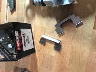
I could not figure out an obvious way that these would fit into the FFR 11.65” rear brake calipers, so I left them out, consistent with the 2013 instructions that I am following. IS THIS OKAY?
I scoured the forums and found answers on both sides. Some posts said the anti-rattle clips are not needed for the FFR-supplied 11.65" rear brakes, but others said the opposite. Finally, a friend of mine (much more experienced with building cars than me) read my build thread and said, oh yeah, you definitely need those anti-rattle clips. So, I sent Dave at FFR an email inquiry, and, as always, he replied quickly and graciously. Here was his response: "The anti rattle clips should be in the box with the rear pads and they install as shown [see below]. They don’t fit our bracket the best so you may want to bend the spring part of the shim so it puts less tension on the bracket."

The statement that “they don’t fit our bracket the best” is an understatement. They don’t fit worth a damn! The picture above is somewhat artificial because you can’t install the brake pads on just the upper half the caliper before it is installed on the lower half. And once you remove the brake pads, the anti-rattle clips simply fall out. Basically, there is nothing holding them in place, other than the brake pads themselves.
Not complaining here, just pointing out to other newbies like me that there’s more to story than the FFR instructions indicate. Per Dave’s suggestion, I put the clips in a vice and I bent the upper portion way back to better contour to the caliper body. Even then, the clips were basically just floating in place, with nothing to grab on to. I solved this problem by zip-tying the clips to the calipers while I installed the inside brake pad (which secures the clips in place) and then cutting the zip ties to install the outside brake pad:


While I was at it, I added some anti-squeal compound to the back of the pads and re-lubricated all the moving parts.
I'm pretty sure there's some better technique than what I employed. In fact, I apologize if this discussion is “old hat” to more experienced builders, but this is the type of thing that trips up newbies like me and causes needless stress, especially when it concerns the brakes.
Anyway, my brake system is now buttoned up, I'm sleeping well at night, and my next step will be the fuel system . . .
-
Post Thanks / Like - 1 Thanks, 0 Likes
-
Senior Member
All my fuel line components have arrived, so I plan to start that project tomorrow. In the meantime, I fitted up the DS footbox floor and inside wall. I have a quick question about the inside wall. Here’s the basic fit-up:
I think I’ve got this fitted properly, but the interface between the inside vertical wall and the transmission tunnel vertical wall seems a bit out of whack. There’s about a 1/2” gap between the two panels that I don’t remember when they were originally assembled:

To be clear, I ‘m sure I can force these two together and rivet in place, but before I do that, I want to make sure I don’t have these panels positioned incorrectly. Here’s a shot inside the footbox, with the DS inside vertical wall dropping down forward of the tab on the DS cockpit floor:

Is that right, or should it go inside the footbox? Also, any advice on the gap between the vertical wall and the transmission tunnel vertical wall.
Last edited by JB in NOVA; 06-12-2020 at 06:23 AM.
MKIV Complete Kit #9822 l BluePrint 347 EFI l TKO600 l Power Steering l Heater/Defrost l
Build Thread
-
Originally Posted by
JB in NOVA
All my fuel line components have arrived, so I plan to start that project tomorrow. In the meantime, I fitted up the DS footbox floor and inside wall. I have a quick question about the inside wall. Heres the basic fit-up:
I think Ive got this fitted properly, but the interface between the inside vertical wall and the transmission tunnel vertical wall seems a bit out of whack. Theres about a 1/2 gap between the two panels that I dont remember when they were originally assembled:
To be clear, I m sure I can force these two together and rivet in place, but before I do that, I want to make sure I dont have these panels positioned incorrectly. Heres a shot inside the footbox, with the DS inside vertical wall dropping down forward of the tab on the DS cockpit floor:
Is that right, or should it go inside the footbox? Also, any advice on the gap between the vertical wall and the transmission tunnel vertical wall.
JB, I too have that same gap, I am thinking of using a tool from Harbor freight that looks like a flat vise grip, time number #98728 (from EdwardBs post) to bend the trans vertical tunnel wall a bit. but not sure yet. ill finish the Front suspension when my pats arrive this weekend.
Ill follow since you are a bit ahead of my build.
-
Post Thanks / Like - 1 Thanks, 0 Likes
-
Senior Member
Originally Posted by
jiriza84641
JB, I too have that same gap, I am thinking of using a tool from Harbor freight that looks like a flat vise grip, time number #98728 (from EdwardBs post) to bend the trans vertical tunnel wall a bit. but not sure yet. ill finish the Front suspension when my pats arrive this weekend.
Ill follow since you are a bit ahead of my build.
jiriza, thanks for the tip. It looks like I'll be purchasing that tool since I have not come up with any other solution or explanation for this gap. In the scheme of things, it's not that big a deal, but most of the other MK4 panels have lined up perfectly, so I'm a little hesitant to bend this panel into place unless it's absolutely necessary. Unfortunately, it's looking like it's necessary.
MKIV Complete Kit #9822 l BluePrint 347 EFI l TKO600 l Power Steering l Heater/Defrost l
Build Thread
-
Post Thanks / Like - 0 Thanks, 1 Likes
-
Senior Member
Fuel lines
After abandoning the idea of running braided fuel lines through the transmission tunnel (per FFR EFI kit instructions), I decided to run 3/8 NiCopp supply and return hard lines along the PS 4 tube. Thanks again, FFR forum, for all your advice on this topic! As with everything else in this build, running the fuel lines was a learning experience, but I got it done.
First, although 3/8 NiCopp is easy to bend compared to steel, it is still (obviously) not as easy to bend as the 3/16 brake lines I had gotten used to working with. So there was a learning curve in figuring out what radiuses I could use with the thicker material. Once I got that figured out, the installation went relatively smoothly, with one minor hiccup.
I had originally planned to run the supply and return lines horizontally side-by-side, similar to what is shown in the FFR manual (see p. 189):

My plan was to secure the inside line using the FFR-supplied clamps, then use these separators from ESpeeder: https://www.amazon.com/gp/product/B0...?ie=UTF8&psc=1 to separate the lines, and then to secure the outside line at the beginning and end of the run to keep everything horizontal. To put it mildly, that plan failed miserably. It looked terrible, and the outside line did not want to stay horizontal.
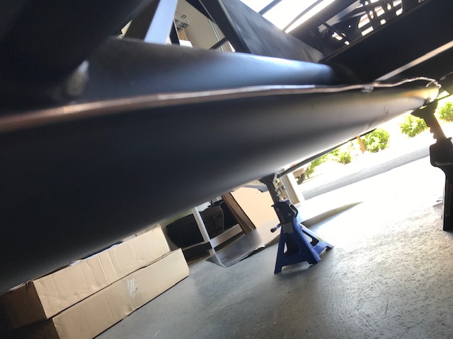
So I changed plans. I aligned the supply and return lines vertically (as many others have done) and used the same ESpeeder clamps to keep them separated. The clamps contoured very nicely with the round 4 tube, but I needed a way to secure them. I drilled the clamps with a ¼ hole, and then tapped the 4 tube to receive a ¼ screw. I used ¼ X 1 stainless steel socket cap screws to tighten the clamps to the 4 tube. They snugged up very nicely. These pictures show the 3/8 NiCopp lines covered by stainless steel gravel guard and secured with the ESpeeder clamps:


MKIV Complete Kit #9822 l BluePrint 347 EFI l TKO600 l Power Steering l Heater/Defrost l
Build Thread


 Thanks:
  Likes:


 Reply With Quote


