-
Senior Member

I may very well be missing something, but is there a reason the inertia switch is upside down?

Originally Posted by
bldr.rob

While we are waiting on the second batch of aluminum to be powder coated as well as waiting on delivery of several others parts to wrap up the brake lines we decided to get started on what, to me and as many others have admitted, the most intimidating part of the build - the wiring. Started laying everything out and got the first piece done before we had to call it a day. I'll call this a win. :-) Unfortunately we are under quarantine until Monday due to my son getting Covid a couple of weeks ago so I'll have to wait until then to get over to the hardware store to get the 1-1/4" bit to drill the 2 holes in the firewall. After that we'll get the wiring fed through the firewall.
Lots of connections to make!

Inertia switch mounted

-
-
Originally Posted by
MSumners
I may very well be missing something, but is there a reason the inertia switch is upside down?
Thanks for double checking me. Before we installed this I looked at the instructions and at another build and I'd swear it showed that it was mounted button down. Should have asked the question. We'll get it flipped. Thanks!
Mark IV Complete kit delivered 7/7/20
Blueprint 427 ordered 11/23/20
-
Senior Member

Looking good, Rob, you're starting in on the part I'll have to face next ... I laid the harness out in the car, then decided to work on the dash before tackling the wiring. I'll be looking for updates as you go through the wiring process and I appreciate the detail you've included.
Cheers,
-- John
MK4 #7838: IRS 3.55 TrueTrac T5z Dart 347
The drawing is from ~7th grade, mid-1970s
Meandering, leisurely build thread is
here
-
Post Thanks / Like - 1 Thanks, 0 Likes
-
A couple observations. 1st, the reason some like to do the corkscrew look is to use up excess rather than cutting and doing the double flair. Some say it is for "vibration" either way, it will work. I found that rather than using a "tubing bending tool" I just use a large socket, say 1-1/16 or so... Just bend the tubing around the socket as needed and you will get nice bends or corkscrews if that is what you want. You can use a smaller socket for a tighter bend, but be careful you don't kink it by going too small.
Some examples, these bends were all done using a socket.
IMG_1482.jpg Rear Brake T fitting.jpg IMG_2338.JPG
-
Post Thanks / Like - 0 Thanks, 1 Likes
-
Originally Posted by
BadAsp427
A couple observations. 1st, the reason some like to do the corkscrew look is to use up excess rather than cutting and doing the double flair. Some say it is for "vibration" either way, it will work. I found that rather than using a "tubing bending tool" I just use a large socket, say 1-1/16 or so... Just bend the tubing around the socket as needed and you will get nice bends or corkscrews if that is what you want. You can use a smaller socket for a tighter bend, but be careful you don't kink it by going too small.
Some examples, these bends were all done using a socket.
IMG_1482.jpg Rear Brake T fitting.jpg IMG_2338.JPG
BADASP427:
I've followed your thread quite a bit. Thanks for all of the great tips and sharing your experience and knowledge, your car looks awesome! What a great idea to use a large socket! I'm not very happy with the bends I have using the tubing bender. Seems like the tubing kept slipping away from me. I have a piece of hard brake line that I've been practicing on - I'll do a test run with the socket and see how it goes. We still have to run the front brake hard lines so hopefully those bends will come out better.
Mark IV Complete kit delivered 7/7/20
Blueprint 427 ordered 11/23/20
-
Post Thanks / Like - 0 Thanks, 1 Likes
-
Originally Posted by
rthomas98
Quick question as I have noticed a few people doing this on the brake lines; is there a reason for the "corkscrew" effect as opposed to cutting and re-flaring. Noticed a few people doing this now and I am about to start the brake lines myself.
rthomas98 - as BadAsp427 noted, I coiled my lines because I didn't want to cut them and re-flare them. It's not difficult but does require a bit of patience(doesn't each area require that?) One helpful tip would be to try to practice on a wire hanger or an extra piece of hard line if you have it. I also used the wire hanger to trace out the path I wanted before working with the hard lines. Good luck and keep us posted on your progress!
Mark IV Complete kit delivered 7/7/20
Blueprint 427 ordered 11/23/20
-
Originally Posted by
John Ibele
Looking good, Rob, you're starting in on the part I'll have to face next ... I laid the harness out in the car, then decided to work on the dash before tackling the wiring. I'll be looking for updates as you go through the wiring process and I appreciate the detail you've included.
Cheers,
-- John
Thanks John. It's slowly coming together. So far, and I don't want to curse myself here, but the harness connections haven't been as difficult as I had gotten myself all worked up over. I know I'm just starting on it and have a long way to go but so far, so good. I was quite overwhelmed when I first started reading through the directions from RF and thought I had a different harness, not enough wires, too many wires, you name it and I was thinking it. I stepped away several times to re-group and took it one step at a time. You'll get there too.
I hit a milestone today! Lit up the gauges on the work bench for the first time! Very exciting!

Mark IV Complete kit delivered 7/7/20
Blueprint 427 ordered 11/23/20
-
Post Thanks / Like - 0 Thanks, 1 Likes
-
Originally Posted by
bldr.rob
While we are waiting on the second batch of aluminum to be powder coated as well as waiting on delivery of several others parts to wrap up the brake lines we decided to get started on what, to me and as many others have admitted, the most intimidating part of the build - the wiring. Started laying everything out and got the first piece done before we had to call it a day. I'll call this a win. :-) Unfortunately we are under quarantine until Monday due to my son getting Covid a couple of weeks ago so I'll have to wait until then to get over to the hardware store to get the 1-1/4" bit to drill the 2 holes in the firewall. After that we'll get the wiring fed through the firewall.
Lots of connections to make!
Inertia switch mounted
Maybe someone has already mentioned this, but I think that inertia switch is supposed to mounted red side up.
-
erstanl - thanks for catching that! we did get it flipped over.
Mark IV Complete kit delivered 7/7/20
Blueprint 427 ordered 11/23/20
-
Post Thanks / Like - 0 Thanks, 1 Likes
-
Factory Five Reservoirs
Had a good day in the garage yesterday. For months I've been trying to figure out how to install the FF reservoirs for the brakes and hydraulic clutch. I wanted to add a reservoir, for 3 total, so that we would have one for the front brakes, one for rear brakes and one for the clutch. However, if we installed all 3 reservoirs with the brackets mounted side by side it would have been about 14-1/2" in total length and from what I understand, the front end of the reservoirs cannot be more than 12" from the front of the DS footbox to be sure they don't interfere with the hoot struts. So, after much forum research and sitting and pondering the predicament, I started working with a piece of sheetmetal to see what I could come up with. The first attempt was just a flat piece bent to support 2 of the reservoirs and 1 was mounted to the front of the footbox per the FF instructions above the accelerator cable. That didn't quite work because in order to keep the 2 reservoirs close enough to the footbox they made it near impossible to open the reservoir that was mounted to the footbox already. Next attempt I dismantled everything and started over. I really wanted to keep all 3 reservoirs together and mounted to the frame rail. But how to do that...... well I decided to offset and overlap the brackets. Hmmm. That might just work. If I did that I could actually get them to fit in the 12" space. So, here we go... A cut here, a snip there, measure, remeasure, clamp, measure, hmm this may work.... let's try a few rivets. So, what I ended up with is a piece that is 1-1/2" wide at the top where it will secure to the underside of the frame rail. It will stand out from the frame 3/4". My understanding is that this should help provide clearance for access to the tops of the reservoirs when they need to be accessed. PLEASE let me know if you don't think this will work. I also added pieces on the ends to help make it more stable. For the piece next to the footbox I will drill it and secure to the footbox panel with a small bolt. So far while clamped in place it seems to be pretty sturdy. I also leveled the brackets and tops of the reservoirs with the ground. The top of the reservoir at the front is about 1/2" below the top of the frame and then the others were set level with that one. Also, I'll cut the lines to the master cylinders down once this is set in final position. Let me know your thoughts if you think I need to add any other support. If everyone thinks this will work I'll get this sent out and powder coated. Thanks for checking it out!


I have more pix in my album if I need to post more to help answer questions.
Thanks!
Mark IV Complete kit delivered 7/7/20
Blueprint 427 ordered 11/23/20
-
Post Thanks / Like - 0 Thanks, 1 Likes
-
Looks like no issues from what I can tell.
-
Post Thanks / Like - 1 Thanks, 0 Likes
-
Senior Member

Looks good... as long as the caps aren't "proud" of the frame-rail, and level to the world you're OK.
John D. - Minneapolis 'Burbs
1965 El Camino - LT-1, 4L60e, 4wh discs, SC&C susp.
2013 F-150 Platinum - Twin Turbo 3.5
2018 Mk4 Roadster w/ Coyote - #9365 - Build Thread Delivery 7/3/18, 1st Start 1/4/19, 1st Road Mile 5/5/19, Legal 6/18/19, In Paint 2/25/21, Done (?) 4/2021
-
Post Thanks / Like - 1 Thanks, 0 Likes
-
Senior Member

Rob, FWIW...
What gauge sheet metal are you using for the bracket? That looks pretty thin, not that it would not work but it might flex quite a bit and vibrate when engine is running. I was less than 8" from the bracket with a CNC setup using a single piece of 1/8" aluminum which is solid and does not flex. If you wanted to have another option you could go with a Jamar that is more compact than your current setup. I might consider something a little more stout to hold the reservoirs. Just my .02 I am definitely no expert on this and I might overkill stuff.
https://www.kartek.com/parts/jamar-p...nd-clutch.html

Last edited by Fman; 01-24-2021 at 10:07 PM.
-
Post Thanks / Like - 1 Thanks, 0 Likes
-
Originally Posted by
Fixit
Looks good... as long as the caps aren't "proud" of the frame-rail, and level to the world you're OK.
Thanks John. There is actually 3/4" space between the vertical face of the frame rail and the vertical face of the bracket where the reservoirs mount to. Do you think that will work? Kind of hard to tell from the pictures but maybe you can see the offset here.
Mark IV Complete kit delivered 7/7/20
Blueprint 427 ordered 11/23/20
-
Fman - thanks! The metal is 26 gauge galvanized. I was thinking if I could get it secured to the footbox it may be sturdy enough to work. With that gauge metal do you think it may not be thick enough to keep things from vibrating? I was hoping to use the FF reservoirs though since I have them. I really like those CNC ones though!! Thanks for looking at it for me!
Originally Posted by
Fman
Rob, FWIW...
What gauge sheet metal are you using for the bracket? That looks pretty thin, not that it would not work but it might flex quite a bit and vibrate when engine is running. I was less than 8" from the bracket with a CNC setup using a single piece of .090 aluminum which is solid and does not flex. If you wanted to have another option you could go with a Jamar that is more compact than your current setup. I might consider something a little more stout to hold the reservoirs. Just my .02 I am definitely no expert on this and I might overkill stuff.
https://www.kartek.com/parts/jamar-p...nd-clutch.html
Mark IV Complete kit delivered 7/7/20
Blueprint 427 ordered 11/23/20
-
Senior Member
Rob, personally IMO I would go with a .090 or 1/8" piece of aluminum and never have to worry about it.
-
Fman - ok, thanks. I'll pick up something a little more stout. Appreciate it!
Originally Posted by
Fman
Rob, personally IMO I would go with a .090 or 1/8" piece of aluminum and never have to worry about it.
Mark IV Complete kit delivered 7/7/20
Blueprint 427 ordered 11/23/20
-
Post Thanks / Like - 0 Thanks, 1 Likes
 Fman
Fman liked this post
-
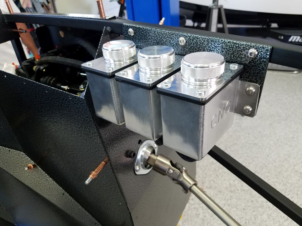
Factory Five Reservoirs - Bracket V2
Second times the charm? I took Fman's advice and found a local sheetmetal shop to cut a piece of 1/8" metal for me so I could try version 2 of the bracket for the reservoirs. This thing is STOUT! 1/8" is definitely the way to go. The shop was also able to include a 90 degree bend at the top so that I can mount it to the underside of the 3/4" frame rail. I've drilled and installed the brackets and reservoirs and have it clamped in place now. The vertical face of the bracket is 1/2" proud of the vertical face of the 3/4" frame rail. I did this to provide better accessibility to remove/ replace the caps. Please let me know if you think this might cause interference elsewhere. Reservoirs are set in place and leveled with the ground. The reservoir brackets are also set level with the ground. I'll cut the tubing and adjust the height of the reservoirs once I mount the bracket for the final time. Right now the forward reservoir is 1/2" above the bottom of the 3/4" frame rail. The wiring harness will also be secured to the 3/4" frame rail once this piece is finalized. If the forum thinks this will work I'll send it out to be powder coated. Thank you!
All leveled up

Back of bracket

Front end of the bracket is 11-3/4" from the front of the footbox

Mark IV Complete kit delivered 7/7/20
Blueprint 427 ordered 11/23/20
-
-
Post Thanks / Like - 0 Thanks, 2 Likes


 Thanks:
  Likes:


 Reply With Quote
