Hmm.... Hadn't thought about the heat right there. Thanks for pointing that out. First build... followed the recommended path from FFR for the most part. The top 3/4" tube will have the reservoir bracket, and the hood gas strut I think. Maybe it would be too crowded to re-run the front brake line up there?
I will now reverse-rationalize my approach, which is what I usually do when I realize I could have made a better decision . Bear with me: I do this to make myself feel better!
- I'm in Canada. Overheating is usually not a problem. Hahaha.
- Brake fluid boils at 400°F, correct? Engine bay temps, generally, may reach 250°F at most (?). Yes, it may be hotter above the exhaust headers on the drivers side. The car will be a cruiser and not tracked, so I think (hope?) that the heat output of the engine won't be consistently hot to the point that brake fluid will boil.
- I ran the line along the top outside corner of the 3/4" tube, so hopefully the tube it self will provide some shielding.
- I have an infrared temperature gun. During go-kart I'll measure the temps in that area and if I'm really worried, maybe I can install some heat-shielding. I think there is some heatshield foil tape that is made for this purpose. It won't look pretty, but I knew going in that I would not be building a show car. I'm not an experienced fabricator by any means.
I'll have to think about this some more. Are there reports of guys actually boiling their brake fluid to the point of brake failure? I would think FFR would have heard about that by now and they would have recommended an alternate routing in their manual
Hmm.... Hadn't thought about the heat right there. Thanks for pointing that out. First build... followed the recommended path from FFR for the most part. The top 3/4" tube will have the reservoir bracket, and the hood gas strut I think. Maybe it would be too crowded to re-run the front brake line up there?
I will now reverse-rationalize my approach, which is what I usually do when I realize I could have made a better decision . Bear with me: I do this to make myself feel better!
- I'm in Canada. Overheating is usually not a problem. Hahaha.
- Brake fluid boils at 400°F, correct? Engine bay temps, generally, may 250°F. Yes, it may be hotter above the exhaust headers on the drivers side. The car will be a cruiser and not tracked, so I think (hope?) that the heat output of the engine wont' be consistently hot to the point that brake fluid will boil.
- I ran the line along the top outside corner of the 3/4" tube, so hopefully the tube it self will provide some shielding.
- I have an infrared temperature gun. During go-kart I'll measure the temps in that area and if I'm really worried, maybe I can install some heat-shielding.
I'll have to think about this some more. Are there reports of guys actually boiling their brake fluid to the point of brake failure? I would think FFR would heard about that by now and I would have recommended an alternate routing.
Thanks!
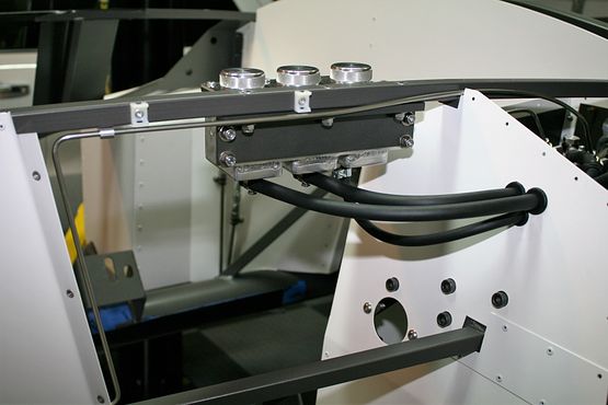
Given the choice, I do run my front brake lines on the outside of the top 3/4" tube. If on the outside, doesn't interfere with either the reservoirs or the hood gas struts. I can't say that heat would be a problem on the lower tube. But it's an easy decision IMO to keep the line further away. FWIW. The clips showing in this picture are for the front harness. Also run along the outside of the top tube.
Build 1: Mk3 Roadster #5125. Sold 11/08/2014. Build 2: Mk4 Roadster #7750. Sold 04/10/2017. Build Thread Build 3: Mk4 Roadster 20th Anniversary #8674. Sold 09/07/2020. Build Thread and Video. Build 4: Gen 3 Type 65 Coupe #59. Gen 3 Coyote. Legal 03/04/2020. Build Thread and Video Build 5: 35 Hot Rod Truck #138. LS3 and 4L65E auto. Rcvd 01/05/2021. Legal 04/20/2023. Build Thread. Sold 11/9/2023.
I decided to try ceramic coating the exhaust headers and side pipes myself. Going with Cerakote C-7600 Glacier Black (air cure). Step one is to burn-off any residue or oils from manufacturing or shipping. Not a full bake, but a step in the right direction.
I had the tiger torch on each piece for about a minute, but surface temps only got up to 120-130°F or so. Maybe the emissivity setting on my infrared temperature gun is off. Or, it would take much, much longer for the heat to soak through all the metal. I repeated the process 3 more times. At any rate, I saw some smoke so I'm confident I at least did some good! Next step will be to degrease, sandblast (headers) or sand by hand (side pipes). The side pipes won't fit in my sandblast cabinet. I'll then degrease and heat one more time before applying the ceramic. Wish me luck!
Headers and Ball Joints
After my first round of burning / heating with the tiger torch, I then sprayed the headers and ball joints with brake cleaner. This is because I don't want to contaminate the glass bead in my sandblast cabinet with any oils. Set the pressure for about 90 psi at the cabinet. I think I got a pretty good rough surface (felt like medium (200) grit emery cloth), and anything I wasn't able to reach or get properly, I finished by hand with some medium grit emery cloth. You can see the before and after in this photo:
Using chain and steel wire, I hung up the headers. The optimum point is high enough that you can kneel down and spray up, but also low enough that you can spray down. Also leave plenty of room to walk around the part completely with the spray gun. I then soaked again with brake cleaner, and let it evaporate for a couple of hours. I then hit the parts with the tiger torch one more time, to get rid of any final contaminants. Let it cool overnight.
Next morning I hit them with the air gun to blow off any dust or glass bead, then masked off the gasket surfaces. Then coated with the C-7600 Glacier Black following the Cerakote instructions. Here are some pics roughly 30 minutes after coating (still wet):
I'll let parts air cure through Boxing Day. Next week, I'll coat the side pipes.
UPDATE: There was some flaking on two of the tubes of one of the headers. Not sure if I didn't blast that area properly, or was it wasn't properly cleaned, or maybe the coating wasn't sufficiently shaken / mixed. I had to re-blast the defective areas. I then took a blowtorch to the bad areas, and after it cooled down, a bit more flaked. So, I blasted those areas clean. I then re-coated. We'll see if it lasts.
Side Pipes
Sure wish I had more room to apply the coating. Shooting from all directions is important. And good lighting! (Or good eyesight.) I think I missed a bit of the mounting on one pipe, but otherwise I think they came out okay.
Wheels
Had my wheels powder coated a satin black. Here is before and after: IMG_9669.jpgIMG_9825.jpg
Tires
Went with Nitto NT555 G2s, 255/40R17 fronts and 315/35R17 rears. The most balance was on one of the larger rear wheels, at 3.0 Oz.
Mounting
I temporarily mounted the wheels without the lug nut covers, tri-wings and adapters. I still need to get some anti-seize for the adapters. I'm also trying to figure out the best way to secure the adapters to the back of the wheel so that it doesn't spin in the bore when you're trying to spin the tri-wings on. Do most guys just use RTV?
IRS Axle Nuts to 45° Past Torque
Dropped the car onto dollies, and locked the dollies from rolling so that I can finish tightening the IRS axle nuts. With just the e-brake engaged, I was able to over-tighten about 20-25° past torque spec, but then the wheel and axle started turning. Now with the wheels on and the car sitting on the ground (dollies), I tried again. Must have put 300 ft-lb on the breaker bar, both sides, and the axle nuts would still not turn any more. I think I'll try again after go-kart testing, to see if anything loosens up a bit. But as it stands now, I was only able to rotate the IRS axle nuts about 20-25° past torque spec.
Being in Canada, some DIY bed liner options are limited. The Dupli-Color kit in town was $170, whereas the same kit by Dominion Seal (Canadian Co), called EZ Liner was $120. Good for fiberglass.
1) Sanded the entire underside with 80 grit paper
2) Vacuum
3) Air Gun
4) Wipe down with clean water
5) Air Gun
6) Wipe down with Wax & Grease remover and let dry for a couple of hours.
7) First coat of EZ Liner.
8) Let coat sit 24 hours (at 70F, if possible)
9) Air gun
10) Second coat EZ Liner.
I did NOT put the accelerator chemical into the mix for the first coat. I knew I'd be putting on a second coat, and I didn't want the liner to set-up in the can overnight. The mixture with the polymer/rubber was noticeably thicker the next day, but still easy to apply. I used 2, 2" paint brushes from the dollar store. I didn't bother with the roller because of those glorious curves in the body!
The motor package from Fortes finally arrived. Haven't done much on the build while it was coming, because I was waiting for upgraded fuel pump in the motor package, so that I could install the tank and get on with the fuel lines, cockpit tins, and the heat and noise insulation.
I didn't know what I would get with the Holly Sniper 12-345 fuel pump. As it turns out... not much! All the 5/16 stuff in the base kit is not useable. Going with 3/8 copper nickle hard line and -6 AN PTFE braided hoses. Just waiting for quotes from a few vendors.
I wanted to at least install the starter on the motor, but the shipping bracket is in the way. I'll have to hoist the motor up before I can complete any motor bits. I had to drive to 3 hardware stores before I could find the M14-2.0mm bolts for the lift points on the motor casing. The lift brackets from TDMotion wiould cost me $130+ Canadian, so I'll make my own brackets. I have plenty of 10mm thick aluminum plate in the shop. 30ksi shear and 40ksi yield... plenty strong enough.
Well, there's 6 hours I wish I had back. A lot of cutting, grinding, and filing. A lot of test fits. A lot of trigonometry. A lot of butter. I seriously think this was the most frustrating part of the build thus far (other than waiting for parts).
There are already a few posts on this topic. I hope someone from FFR takes some of these mods into consideration, as they may save future customers some aggravation and time.
My novice advice for those about to modify the Coyote accelerator pedal and FFR supplied mounting bracket:
Follow the initial instructions on modifying the pedal.
Bolt the pedal to the mounting bracket, then grind the pedal 'ears' to match the profile of the bracket ears. An angle grinder with a flapper disc works fast, so be careful and then finish the final strokes with a rasp file.
Grind the right side of the top tab of the mounting bracket, so that you can push the bracket as close as possible to the inboard footbox panel.
Grind the right side of the mounting bracket where it touches the 3/4" square tube in the foot box, again, this is to allow you push the mounting bracket to the right.
On the right side of the pedal, grind off any unneeded webbing where it would touch with 3/4" square tube in the foot box.
On the mounting bracket, grind or file the left-side of the top mounting hole, essentially to slot the hole (perhaps 1/32 to 3/32)
On the mounting bracket, grind or file the top-side of the bottom mounting hole, to slot the hole (perhaps 1/32 to 1/16)
The purpose of all this is to shift the mounting bracket to the right, and also turn it slightly clockwise, in order to increase the clearance between the top bolt ear of the pedal with the steering shaft. And because the steering shaft comes up at an angle, you may find that you'll also have to file the front-side of the pedal ear, around the periphery of the bolt hole.
You'll also find that in order to do test fits, you'll have to get the pedal up and into place first, and then get the mounting plate up and into place. Unless the inboard footbox panel is off, you won't be able to get the pedal into place if the mounting bracket is bolted in.
2) The Chassis Wiring Harness instruction booklet says to cut 3 holes if using an EFI harness. It also says to 'check the hole size needed for the EFI harness grommet before drilling any holes.' I thought this note was referring to the Coyote Fitment instructions, above!
3) The actual Gen 3 Coyote Gen 3 Controls Pack Harness grommet is only 1 1/2" diameter!
So, if you're about to install a Gen 3 wiring harness, open the pack, cut the zip ties and unfurl the harness, and measure the grommet.
And if Factory Five Tech is reading this, it would be BETTER to just eliminate the 2" hole size instruction from the harness booklet. Just tell people to measure the grommet on the harness and then cut the hole to suit.
I have some spare aluminum to patch the hole and then re-bore the hole.
UPDATE: The Coyote EFI controls pack harness has a Kennard 720 Grommet for the firewall, which requires a 1.5" bore hole.
Okay, I admit I haven't been keeping up with the build posts. One of these days I'll sort through my photos and log book and post some info that may be of help to others.
But today is a great day: first start! Made a short video:
Learnings on Coyote Gen 3 first start:
1) There is divided opinion on whether or not the oil circuit of a crate Coyote from Ford needs to be primed. Mine was assembled to the Tremec TKX by Mike Forte, and all the fluids were drained. I erred on the side of caution and did the garden pump sprayer method, through the OEM oil pressure sensor port, to prime the oil circuit. It took about 800 mL (almost a full quart). I used a stethoscope on the valve cover to listen for the gurgling oil.
2) At first start (no memory in the ECU, I suppose), with the key on the ON/RUN position, there is no constant 12V to the fuel pump. The fuel pump won't turn until you turn the key to START. (Well, at least when you wire the according to the Ford Coyote EFI fitment to the Ron Francis harness.)
3) Takes an agonizing (for a newbie) ~10 seconds or multiple cranks to fill the fuel lines and fuel rail with fuel. I had to tap the accelerator before it finally fired up.


 Thanks:
  Likes:


. Bear with me: I do this to make myself feel better!


 Reply With Quote