-
Senior Member


Originally Posted by
wallace18

Super job on the wheels!

Thanks
-
Senior Member
-
Senior Member
Rear-End unpacked and Differential Alum Cap with End-Cap support
I uncrated the Moser Rear-End and hosted up and out with my engine crane. I bought an attachment for my engine stand that held the rear-end horizontal (see pic 1 below).

After mounted on the stand, I rotated it to have the chrome diff cover that came with the rear-end point up for easy removal. The cover was surprisingly pretty heavy stamped steel (which was nice to see). Anyway, the gasket under the cover also had RTV silicon used on both sides of the gasket. So, I scraped it all off, cleaned up some of the powder coating that blead over to the face of the machined matting surface so all was smooth and flat. I cleaned the surface with Acetone and then applied my black RTV under and on top of the gasket (pic 2 below). If anyone does this, make sure your RTV bead is on the inside of the bolt holes.

In the next pic below, I have the new Moser heavy aluminum cover mounted with snugged down mounting bolts. Before mounting the new cover, I backed out the End-Cap bearing support lugs all the way out and applied pipe sealer to the threads per the instructions to help eliminate and gear oil seepage.

Then I torqued down the Moser cover to 25 ft/lbs per the instructions.

Lastly, after torquing all the mounting bolts, I then torqued down the bearing end-cap lugs (i.e., load bolts) against the end caps to 5 ft/lbs. Once that was completed, I then installed the jam nuts on the bearing cap lugs and torqued to 10 ft/lbs.

With the new cover in place and every nut and bolt torqued down to specifications, I then added 4oz of Ford's Posi-Traction friction modifier followed by ~2.5 gts of Lucas HD High Perf 80W-90 gear oil (non-synthetic oil). I'll break-in the rear-end per Moser's instructions then after ~500 miles, I'll change oil to a synthetic gear oil.
Thanks all,
Mark
-
Senior Member
-
Senior Member
Very good news for me.... Factory Five Dan Golub contacted me to confirm my order and pickup for 3 Apr. I contacted Stewart Transport for pickup/delivery.... so fingers crossed I receive my '35 extended cab truck in the 1st or 2nd week of April
Mark
-
Senior Member
Alt and pulley install
I pre-ordered some FF parts before the actual '35 kit delivery, i.e., Diff, front and rear WilWood brakes, Gen 3 Coyote install kit, and the A/C kit. I'm really glad I did... since I ordered them back in Nov 2022 and I'm still waiting on the rear brake kit and several missing parts, e.g., brackets, A/C compressor, A/C dryer, hoses, etc.
The first picture is the Alternator bracket. I first cleaned the bracket to remove all oils, then prepped it with phosphoric acid to etch it (it also leaves behind a Phosphorous/Zinc coating that helps prevent rust and acts as a great base for primer/paint. Then I primed with an acid etching primer (3 coats) followed by a metallic silver top coat (3 coats).

For the aluminum spacers to stand0off the alt bracket from the engine's timing cover I cleaned and etched as above, then coated with several layers of clearcoat.

In pic 3 and 4, the 160amp alternator is installed


The kit also included a new pulley that replaced the Ford OEM pulley (top one) and a new belt tensioner (bottom)

Up next I'll be installing the WilWood front hubs to the rotors and safety wiring them.... more on that later.
Stay tune.... much more to follow now with the '35 truck kit arrival in early April.
Mark
-
Senior Member
Front WilWood big brake kit received and some assembly
Another mile stone reached yesterday...... Sally from Factory Five requested final payment for the Apr 1 order ready date. It's now paid and I can't wait for the delivery from Stewart Transport.
Also, as I stated earlier, I preordered last Nov 2022 some items, i.e., Moser diff, front and rear Wilwood big brake kits, etc. Well, I did receive the front WilWoods and have assembled the front hub caps to the rotors. Not the most fun job adding the safety wire to the bolts.... but it's now done. Prior to the safety wire, per WilWood directions, I added a drop of LocTite 271 and torqued each bolt to 155 inch lb. They were very specific to use a 1/4" drive torque wench..... and I see why as 155 inch lb is = to 12.9 ft lb which is a little over hand tight (well maybe a little more that hand tight, but not much!)
Mark


-
Originally Posted by
mkassab
Well, I pulled the trigger and made a really big Summit Racing order, $21k+ to purchase the Coyote, Tremex T56 six speed manual trans, Engine control module, QuickTime bell housing, Tilton billet Dual dick clutch, Tilton Billet fly wheel, Tilton Hydraulic Throw-out bearing electric, starter, 304 SS exhaust parts to have the exhaust exit the rear of the truck bed, 304 SS "H" pipe for the exhaust, electric emergency brake (I'll delete the hand e-brake) and lots of misc. things. I'll report out on all that when it starts to come in. My WiseGuy leather bucket seats should be here soon and I'm still waiting on the wheels. I also order some parts from Factory Five that should be hear soon, e.g., Coyote A/C package, Moser rear end, Wilwood Brakes, Coyote engine install kit, etc.
Pic 1 below shows the garage door opener I'll install. I'll fabricate an upper front roof panel to hold the opener, clock and a few more items (e.g., switches, gauges) to help keep the dash cleaner. More on all that later.
Pic 2 below SS Tie-Down loops.

Pic 2 shows the polished stainless steel (marine grade) tie down loops. I'll attached one to each corner of the wood bed. My wood bed will be fabricated in such a way so I can lift it out of the bed after I release some attachment points. I also want to try to have the gas fill cap located on the right rear bed side panel to keep the wood bed "whole" and without anything attached to it except the SS tie downs.

Stay tuned,
Mark
Mark
You may want to check this out. Not me but a build I have been checking out while making plans
https://www.youtube.com/watch?v=IkKe...ndex=64&t=603s
-
Senior Member

Lots of interesting things going on with this build. Very nice. The seats from WiseGuys look great. I'm really happy with mine but they do take up a little extra space in the standard cab. Yours should be perfect with the new extended cab. Since I'm going through paint right now with mine, I had to laugh a little (to myself of course) at the added colors and pinstriping you're planning for your final paint. My painter is not happy about all the details and amount of hand work to sand and polish. I've been helping so he's been a little less grouchy. 
Build 1: Mk3 Roadster #5125. Sold 11/08/2014.
Build 2: Mk4 Roadster #7750. Sold 04/10/2017.
Build Thread
Build 3: Mk4 Roadster 20th Anniversary #8674. Sold 09/07/2020.
Build Thread and
Video.
Build 4: Gen 3 Type 65 Coupe #59. Gen 3 Coyote. Legal 03/04/2020.
Build Thread and
Video
Build 5: 35 Hot Rod Truck #138. LS3 and 4L65E auto. Rcvd 01/05/2021. Legal 04/20/2023.
Build Thread. Sold 11/9/2023.
-
Senior Member
Originally Posted by
THUNDERSTRUCK
Thanks Thunderstruck..... I was planning to do a truck side install for the gas fill.... I'll have to look for the flex gas filler hose.
Mark
-
Post Thanks / Like - 1 Thanks, 0 Likes
-
Senior Member
Originally Posted by
edwardb
Lots of interesting things going on with this build. Very nice. The seats from WiseGuys look great. I'm really happy with mine but they do take up a little extra space in the standard cab. Yours should be perfect with the new extended cab. Since I'm going through paint right now with mine, I had to laugh a little (to myself of course) at the added colors and pinstriping you're planning for your final paint. My painter is not happy about all the details and amount of hand work to sand and polish. I've been helping so he's been a little less grouchy.
Thanks Paul.... I know the extra details with paint will be a lot of extra work, however, I only plan to do this once (promised the wife) and I want to go the extra mile to make my '35 truck unique.
Mark
-
Looking forward to build.
-
Senior Member
-
Senior Member
WilWood Rear Brakes installed
Today, FedEx delivered my rear WilWood brake kit. I installed them on the Moser rear end.


But, I do have a question on the emergency brake setup I posted in the '35 truck "non-build section".... link: https://thefactoryfiveforum.com/show...cy-cable-setup
Hopefully someone can help me out with your thoughts/direction.
Thx Mark
Last edited by mkassab; 03-27-2023 at 02:38 PM.
-
Originally Posted by
mkassab
Today, FedEx delivered my rear WilWood brake kit. I installed them on the Moser rear end.
But, I do have a question on the emergency brake setup I posted in the '35 truck "non-build section".... link:
https://thefactoryfiveforum.com/show...cy-cable-setup
Hopefully someone can help me out with your thoughts/direction.
Thx Mark
Those look like they take up less space than the Mustang brakes. My Mustang brakes hit the inside of my wheel. I had to use spacers. I hate spacers.
-
Senior Member
Originally Posted by
RuffShod
Those look like they take up less space than the Mustang brakes. My Mustang brakes hit the inside of my wheel. I had to use spacers. I hate spacers.
RuffShod, from my understanding all '35 trucks, regardless of brake brand, needs 1"+ wheel spacers for the front and rear. I can't verify that until I get enough of my suspension built to mount my wheels for fitment and clearance. Once I can actually try the wheel mounting, I can then determine the the thickness of needed wheel spacers. I'll post my findings in this build thread.
Mark
-
Post Thanks / Like - 1 Thanks, 0 Likes
-
Senior Member
Rotated Emergency brake leavers
Well, while I was looking into the rotation of the WilWood emergency brake leavers I did figure out that they can be rotated. (Ref previous post above)
I just removed the 13mm nut from the stud holding the moveable leaver and used a small prybar to gently pry off the emergency brake leaver. The stud has the male side of a splines with the leaver having the female splines as the picture below clearly shows.

So, since I did had the left side apart, I went ahead and rotated the left side emergency brake leaver and cable standoff counterclockwise two screw holes. As you can see, a two hole rotation moved the emergency cable from the 6 o:clock to the ~5 o:clock position. Once I have the rear-end and truck bed sides installed, I'll rotate further is needed. By doing this, the cable sweeping bend will be less then 90* and less likely to lay on the control arms.

I finished up by rotating the right side clockwise two screw holes to match the left side.
Lastly, I received another item I ordered last August 2022..... i.e., my Dakota Digital main speedo, tach, fuel, oil, water temp and volt main instrument cluster I ref'd early on in this post on page 1.
So with many pieces of the "build" puzzle coming together, all I need is the main '35 truck kit.... hopefully next week. I'm just waiting to hear a firmer date from Stewart Transport.
Stay tune.... so much more coming soon.
Thx Mark
-
Mark, my truck is scheduled for completion April 8. Maybe we’ll be on the same delivery truck. Can’t wait to get started. DonS
-
Senior Member
Originally Posted by
mkassab
Well, while I was looking into the rotation of the WilWood emergency brake leavers I did figure out that they can be rotated. (Ref previous post above)
I just removed the 13mm nut from the stud holding the moveable leaver and used a small prybar to gently pry off the emergency brake leaver. The stud has the male side of a splines with the leaver having the female splines as the picture below clearly shows.
So, since I did had the left side apart, I went ahead and rotated the left side emergency brake leaver and cable standoff counterclockwise two screw holes. As you can see, a two hole rotation moved the emergency cable from the 6 o:clock to the ~5 o:clock position. Once I have the rear-end and truck bed sides installed, I'll rotate further is needed. By doing this, the cable sweeping bend will be less then 90* and less likely to lay on the control arms.
I finished up by rotating the right side clockwise two screw holes to match the left side.
Lastly, I received another item I ordered last August 2022..... i.e., my Dakota Digital main speedo, tach, fuel, oil, water temp and volt main instrument cluster I ref'd early on in this post on page 1.
So with many pieces of the "build" puzzle coming together, all I need is the main '35 truck kit.... hopefully next week. I'm just waiting to hear a firmer date from Stewart Transport.
Stay tune.... so much more coming soon.
Thx Mark
Good find on the Wilwood e-brake adjustment. Thanks for posting the details. I played with mine some today. Bored waiting for the last few parts to be back from the painter I guess. It works exactly as you described. With the locking screw and nut removed, was able to pry mine off and try softening the 90 degree angle my cables are at. As it turns out, since I have the cables routed and tied down, wouldn't naturally rotate without putting additional strain on the cables and I really didn't want to re-do the whole setup. Had I noticed the adjustment possibility before (or you posted this about a year ago  ) I might have done it a bit differently. But mine work fine as is, so put it back the way it was. For the record, even at the angle mine are at, they aren't close to the lower control arms. So that's not an issue. Regardless of angle, you may find they interfere a bit with the bed sides. I relieved the bottom of the bed sides a bit on mine so they weren't rubbing hard against them. Not noticeable because it's on the underside plus I have fenders.
Build 1: Mk3 Roadster #5125. Sold 11/08/2014.
Build 2: Mk4 Roadster #7750. Sold 04/10/2017.
Build Thread
Build 3: Mk4 Roadster 20th Anniversary #8674. Sold 09/07/2020.
Build Thread and
Video.
Build 4: Gen 3 Type 65 Coupe #59. Gen 3 Coyote. Legal 03/04/2020.
Build Thread and
Video
Build 5: 35 Hot Rod Truck #138. LS3 and 4L65E auto. Rcvd 01/05/2021. Legal 04/20/2023.
Build Thread. Sold 11/9/2023.
-
Post Thanks / Like - 1 Thanks, 0 Likes
-
Senior Member
-
Senior Member
-
Post Thanks / Like - 0 Thanks, 3 Likes
-
Senior Member
Inventory
Here's a quick update. I've completed the inventory of all the parts, pieces, nuts and bolts.... there's a lot of "stuff" here. My POL list isn't as bad as I thought it would be. I think FF owns stock in paper and cardboard as they pack this all very well. I'll be making a dump run this morning.
Here's a few pics of some of the "inventory".


I'll get the fiberglass body parts washed today. I also have plastic bins and shelves I'll place many of the parts you see.
Now, I need to plan better the order I want to do the build in taking into account all the modifications and additions I want to make. Better planning now will save a lot of headaches later.
My wife and I have a planned week in Pensacola, FL area next week. In some of my downtime, I'll work the priority list, read the install manual in detail, take notes, etc. I also want to add to Factory Fives wire diagrams for all my additions to the diagram. I do a lot of extra electrical "sub (fuse) panels" like Paul B does. Keep the wires as neat as possible and remove or shorten what's not needed. All along the way, keeping in mind future needs, changes, maintenance, trouble shotting, and access if the need arises.
Lastly, now that I have good measurements for the bed, I'll be contacting BedWood ( https://bedwood.com/ )to order the wood and metal needed. I've decided on Black Walnut lumber.... it will be a nice contrast with the light green body paint I'm going with.
Stay tuned,
Mark
-
Post Thanks / Like - 0 Thanks, 1 Likes
-
Put everything back in the box it came in.
You will thank me later.
Have fun!!!
-
Senior Member
"Put everything back in the box it came in.
You will thank me later.
Have fun!!!"
Too late.... all boxes were broken down and I just returned from the dump.
However, I labeled each bag/part with the box #.... e.g., everything from box 5 has a 5 on it and all group/stored together.
So I won't have any trouble fining anything and without the room being taken up by boxes.
Thx Mark
-
Post Thanks / Like - 0 Thanks, 1 Likes
-
Senior Member
Starting the Build
Now that the inventory is complete and my detailed MIK (Missing parts List) is itemized and sent off to FF, I'm starting the chassis build. I plan to add/fabricate some options that will require welding, etc. to the frame. I'll document all that as I do it.
First up I laid out the floor panels, starting with the bottom ones. Used some hand clamps to hold in place.

Then, from inside the cab, I traced out the frame on to the bottom panels

I then proceeded to remove the bottom panels and do the top panels the same way.
Next, I started to prep the rear end so I can get it mounted and installed for some of my mods. First, the adaptor plate. Before install, I primed with acid etching primer. Following the instructions, added some blue LocTite.

Then torqued to 41 ft lbs. To hold the flange adaptor in place to torque, I installed the 4 remaining bolts that will be used to attach the drive shift that allowed me to use a lever and torque wrench at the same time. This worked well.

Then, my first issue. My next step was to mount the lower and upper control arms. On the lower control arms (LCA), the bushings and sleeve were preinstalled at FF. Problem is, the sleeve inside diameter is 12mm but the mounting bolt and bracket are 14mm. Based on other threads, this is a repeating problem and not unique to my LCAs. So I added new 14mm bushings and sleeve to my MIK list and notified FF. I'll have a temp fix for my mockup and use some 7/16" bolts to attached the LCAs to the rear end brackets.

Two of the mods I'll work on next will be relocating the attachment points for the Panhard bar... I have to move the Panhard bar towards the rear to allow clearance for the Moser diff cap I installed and I have to mockup/weld the airbags to the axels and frame.
more coming up soon,
Mark
-
They make an adaptor to move the panhard bar.
I will find it.
-
-
Senior Member
Originally Posted by
RuffShod
They make an adaptor to move the panhard bar.
I will find it.
Thanks.... I'll check it out..... but may not needed it.
Mark
-
Senior Member
Misc update
Quick update....
Yesterday was an "Odds and ends" day. First, I tapped the bushing cylinders for the grease fittings. All were pre-drilled by FF. According to FF, you just use the grease fitting to thread them in?? I didn't like that.... so I determined the zerk grease fittings were metric M7 x 1.0 thread. So, I tapped each one.

Another thing I do for any build is use a product like Eastwoods Internal Frame coating rust preventer. This stuff is great. Each can comes with an 18" spray tube with a brass 360* spray fitting at the end. So any access (hole, opening, etc) you can feed the spray tube into it, press the spray button and slowly pull the tube out.... thus coating the internals with with "green" rust preventer. I will say FF didn't leave open many access holes to the frame.

The rear part of the frame has four vertical down 1" sq tubes I coated the inside with the coating. Any holes I create in the frame, like drill holes for wire or hangers/fasteners, etc, I'll apply this coating.

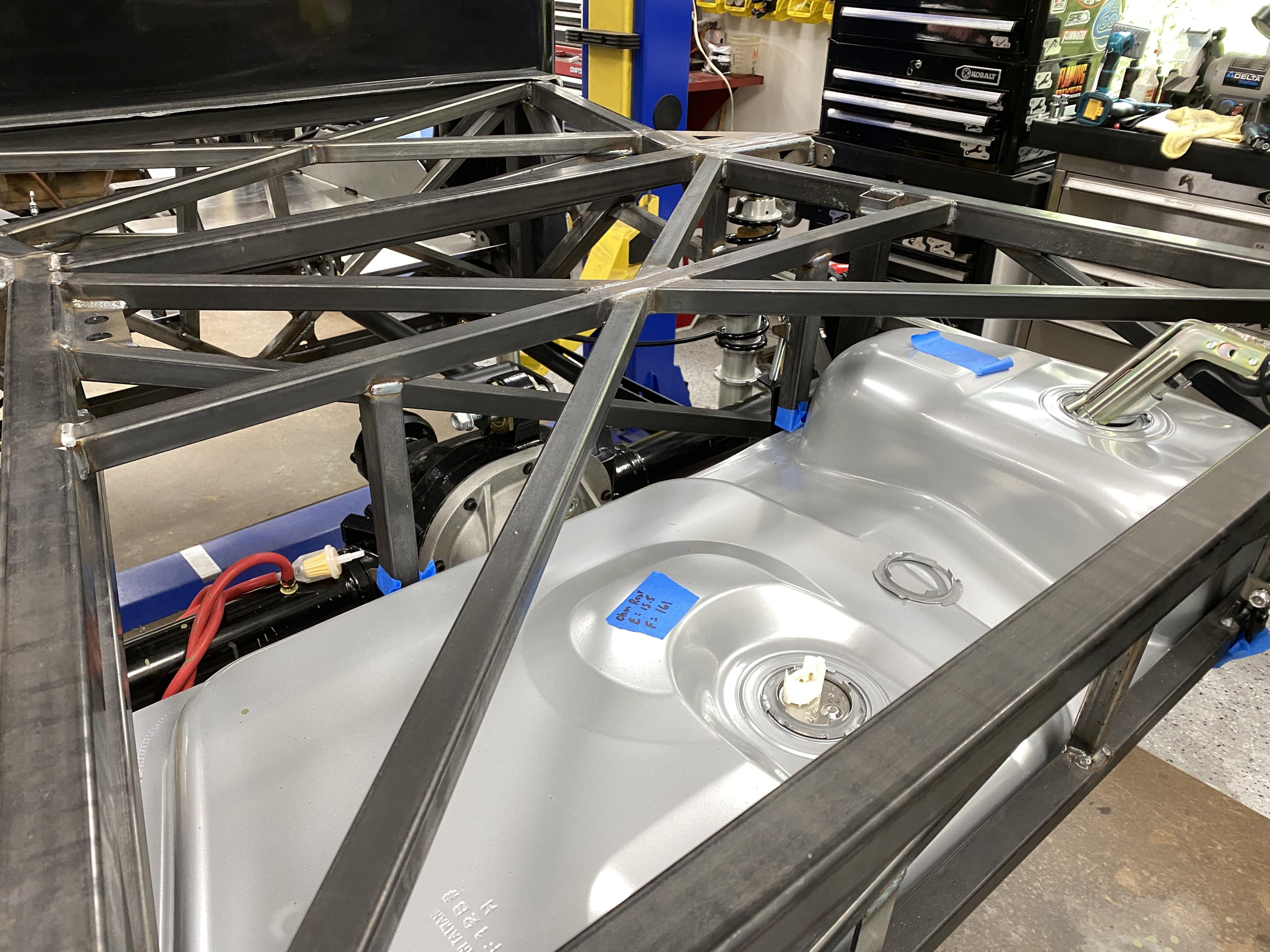
I finished mocking up the rear end and gas tank in preparation to fabricate my air bag base/top plates to the axle (base) and frame (top plate). I'm targeting this install just behind the shocks.... weld the base plate to the axel tube and then fab the upper top plate to the frame.

In this shot, the gas tank "loosely" in place. I took an ohm reading of the FF supplied fuel tank level sender and got 15.5 ohm empty and 161 ohm full readings. I can then use these reading for my Dakota Digital gauge setup to have actuate fuel level readings. Paul (aka edwardb) confirmed for me that FF uses a Mustang standard sender at a 16-158 ohms range.... so I'm good to go.
Lastly, note the red breather tube on the Diff/rear end axle tube and the gas filter stuck in its end. I always do this gas filter addition to prevent any debris/bugs getting in there. On the final build, I'll mount this to the frame above with the filter pointing down.
I'm also looking at a stainless steel battery drop down box vs the FF battery location. This way I can use the FF location for something else and have very easy access to the battery without having to remove the bed or cut access holes in the bed.... although the access would be from below the truck which wouldn't be a big deal. I'll take my time here to further consider what I'll do with the exhaust, etc. to avoid and interference issues down the road.
Stay tuned.... busy day ahead.
Thx Mark
-
Post Thanks / Like - 0 Thanks, 2 Likes
-
Senior Member
Fuel Pump and Air Bag placement?
Yesterday was another misc day..... I spent a lot of time cleaning steel, grinding weld spatter from the FF parts (not too much of that at all), installing the Pro-M Racing Fuel Pump assembly and determining where and how to mount the Air Bags.
Referring to the last picture above in the previous post to this thread, you'll note the fuel pump assembly leaning out of the fuel tank hole where the pump is to be installed. The reason is the return fuel line pipe has a flare out (slight bend out) from the pump body preventing the assembly installation (look closely and you'll clearly see it). I want to point out this is not the pump hanger supplied by FF as it's an aftermarket unit from Pro-M Racing that allows better fuel flow, has AN fittings, and prevents issues the stock Mustang hanger supplied by FF has, namely aeration of the gas. Pro-M have video on this.... here's the link: https://www.youtube.com/watch?v=3osqtEtIEig Pro-M instructions would have you modify the tank opening to allow installation. I didn't want to do that if possible. The picture below shows a closeup of the pipe interference.

What I did was remove the 4 screws that attached the pump hanger from the top assembly. This allowed me to swing the pump body enough to allow the return pipe to enter the tank. Once the return pipe was inside the tank I simply reattached the pump body back to the top assembly. Here's a closeup of the bracket/top assembly without the screws.

Once this was done, everything fell in place for final installation.
The last part of this post is documenting the possible placement locations of the air bags. All the parts for the air bag systems I bought separately, i.e., short air bags, universal mounting plates I can cut/modify as needed, air pump, hoses, etc. The picture below shows a location just behind the shock and under the chassis frame with the base place only. This would be a good location except once the weight is on the suspension, it would be too short (i.e., not high enough for all the parts).
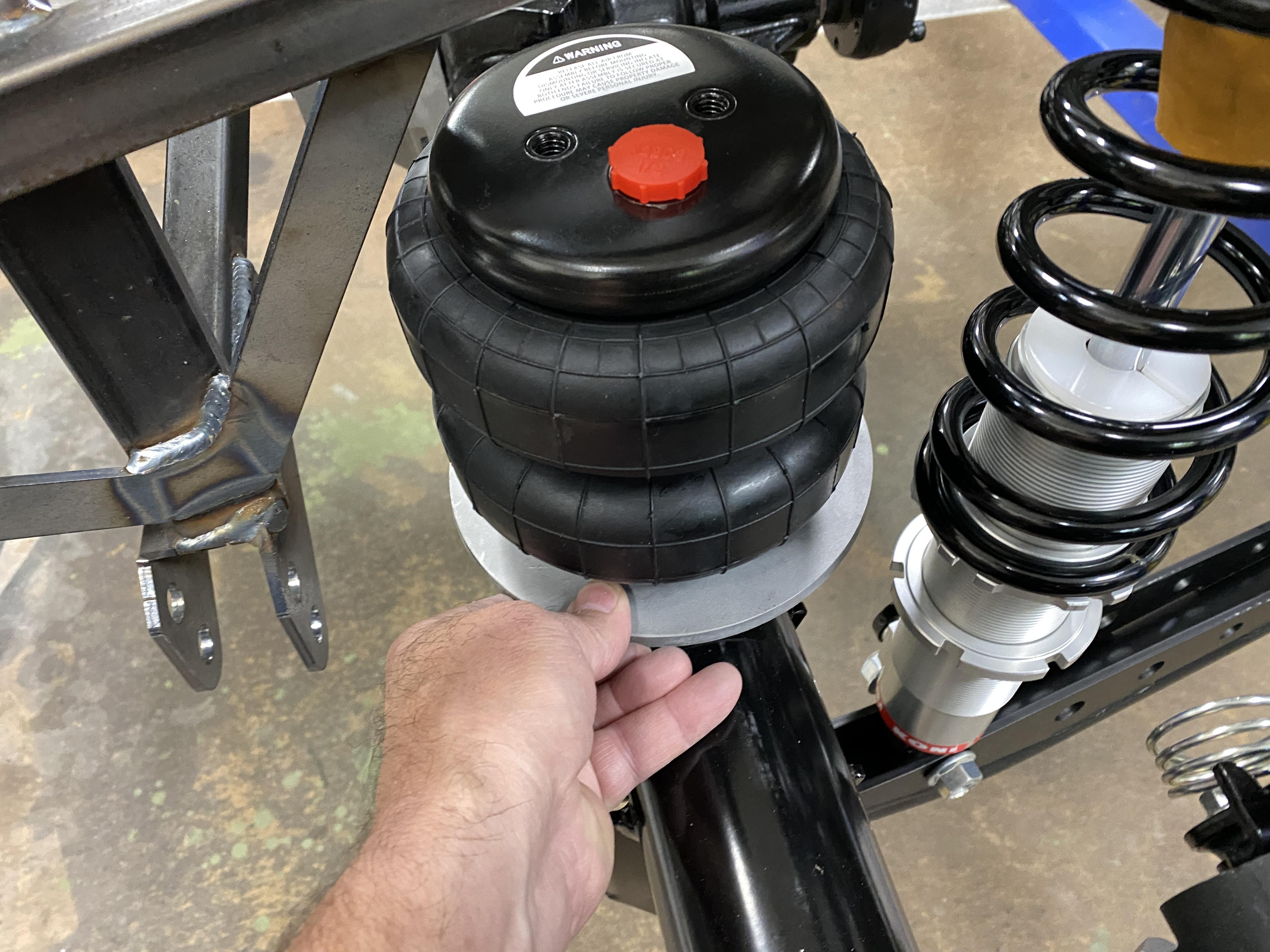
This picture add the top plate to the mix

The only other two location would by inboard of the frame or outboard of the frame. Inboard concerns I considered were possible interference of the exhaust (I want to have options for the exhaust.... more on that later). Moving outboard, the concern was the truck side bed room with the bed side and the frame and how to add the top plate and how it would be attached to the frame. The picture below shows if I mount the base plate to the rear of the axel tube I had room in all the areas of concern and I could fabricate the mounting brackets easily. I'll get the base mocked up and welded in place, but will have to wait to fabricate the top sections until I have the weight on the suspension. This outboard location is also optimal for the weight distribution, i.e.,. the closer to the hub the better.

I'm still determining the mounting location for the air compressor. I was thinking inside the cab under the seat, but with all the room above the gas tank I'm rethinking it. Above the tank has other possibilities too, e.g., cooling radiator/fan, storage, tool box, etc under the bed.
So much to do, but I have time... stay tuned.
Any thoughts on the air bag mounting options most welcome.
Thx Mark
-
Senior Member
Parts cleaning and paint
This is a bit of a boring update, but, an update non the less. And, Yes, I know this one is pretty basic.... but I've had some PMs asking for this sort of thing so newbie beginners to the "Built, Not Bought" get a full picture of what all may be needed.
I haven't installed the front suspension yet because all my steel parts and frame are bare metal (no powder coating) and I didn't want to install bushings, etc. before prep and painting. Therefore, yesterday I spent getting these parts painted so I can move on.
First, using angle grinders, 3M scuff pads and some minor filing, I cleaned up the parts the best I could. I'm not concerned with perfection for two key reasons.... 1) this is a daily driver for me and not a trailer queen show truck and 2) since I'm installing fenders, running board, hood and engine sides most of these parts won't be that viewable.
The next steps were to wash the parts to degrease using POR-15 Cleaner Degreaser. Once that was done, I rinsed with water and blew dry with compressed air. Follow this step, I then used POR-15 Metal Prep. This step is very important and useful. POR-15 (like Eastwood's After Blast) is an acid base product (phosphoric acid) that preforms two key benefits... 1) it etches metal to give paint something to grab hold of and 2) maybe most important, the process leave a phosphorous/zinc coating on the metal that further promotes paint adhesion and helps prevent any rust/oxidation. The picture below shows some parts hanging ready for paint that just went through all these steps (look closely as many parts are lost in the background. I just raised my frame on the lift and hung the parts from the frame).

Next, using POR-15 Rust Preventative permanent coating, I applied two coats per the instructions. I used a disposal brush... but this product flows out pretty smooth. Again, good enough for my purposes. Note: this product is not UV safe and needs a top coat after a few hours of drying. This pic below shows the results of this step.

Lastly, I topped coated the POR-15 with Rust-oleum rattle can Hammered Dark Bronze. I applied several coats. Here's the finished product.

Today, I'll install the bushings & sleeves, grease fittings and install to the frame. I don't have my Koni Dbl Adj shocks yet from FF, so I'll have to devise a way to hold the front struts up until I receive them. From there, I think I'll move on to the firewall and engine/trans install for mockup purposes.
Again, any lessons learned from any of you would be most welcome as I'm just doing what I think best. If there's a better way that would allow "less" rework later I'm all ears.
Thx Mark
-
Post Thanks / Like - 0 Thanks, 1 Likes
-
Senior Member
Front suspension, big brakes and battery
Honey do list prevented any significant work in the past day or so.... but here's a quick update.
I have the front suspension built, e.g., bearings/sleeves installed and greased, hubs and spindles and all installed on the frame. I got a little tickled when it came time to mount the hub to the spindle and the spindle nut holding the hub on is a 1 7/16" socket size @ ~225 ft lbs. I was thinking the ad from FF saying the average garage tools guy could build a car.... well, I don't think many have a socket that size and a torque wrench that can go high enough to torque properly. I suspect most have to take their spindle and hub to a shop mechanic to have this done for them??? Anyway, I'm fortunate to have the socket size and a 3/4" drive Torque wrench that goes past 500 ft lbs..... the picture below shows the torque being applied to the spindle nut.... I mean this torque wrench is ~3+' long.

Anyway, I only call this out for those that may not have the tools needed and a possible solution.
A pic of the finished front suspension

I then installed the WilWood front big brakes, calipers and rotors.


Lastly, I bought a large Odyssey battery and drop down battery box I'll install under the bed, passenger side.

Over the coming days, I'll focus on the air bag & compressor install, engine and trans install.
Thx Mark
-
Senior Member
Engine in, steering rack in, firewall in, Pwr Steer in, Headers on
I'm making some very visual progress with significant "dry fit" mockup, i.e., Coyote engine installed, Trans installed, Rack & Pinion rack steering installed, fire wall installed, elec power steering installed, and headers installed.
First, I setup the engine crane/hoist with the leveler and 4 ratchet straps connected to the front and rear header bolts on both sides. With the Coyote's tight fit in the chassis and against the firewall, this was the best solution I could think of for easy connections and disconnect..... especially with only one person, i.e., me, doing this alone. I took my time and all went fine. I ended up having to remove the cleco clips on the firewall directly behind the engine for lack of room. I also removed the elec power steering unit and reinstalled after the engine was in place. You'll also notice I mounted the rack & pinion steering... no interference there.

Engine & trans mounts now supporting the full weight of the the installed engine.


Shot of the bottom of the engine bay. Oil pan is the lowest object. Elec Power Steering unit reinstalled.

Here's a pic of the left side header. Both the left and right headers were easily installed, after the engine was installed, from the bottom, up through the chassis. I intend to wrap the headers during final build to help control heat. I also want to state.... I don't know who builds these headers, but they are a work of art!

Now that all this is mocked up, I can start laying out the exhaust, electric emergency brake, drop down battery box, air compressor, steering linkage, Brake and Fuel lines, "stuff" that mounts to the firewall, etc.
Stay tuned,
Thx Mark
-
Post Thanks / Like - 0 Thanks, 1 Likes
-
Senior Member
Exhaust mockup, H Pipe, Resonator & Mufflers 1 of 2
Yesterday, I made good progress on the exhaust system. With the Coyote engine and headers installed in the chassis this is a great time to mockup the layout. I plan to weld all and avoid clamps where possible. Since I'm adding resonators, "H"-Pipe crossover pipe and pushing the mufflers out under the bed I'll use and cut up a lot of what FF supplied. I also bought additional SS exhaust pipe sections (e.g., straight, U, 90* and 45*) to use as I need to accomplish my goal.... so what is my goal? Well, I do want my truck to be a bit quieter then just the FF mufflers would provide and I want to eliminate/reduce any possible drone, move as mush exhaust sound out the back of the truck vs under the cab, move as much exhaust heat out the back of the truck as I can and have a system I can unbolt in a few locations and drop the entire exhaust system if I ever need to.
I decided on an H-Pipe crossover vs the X-Pipe. The H-pipe crossover provides three key benefits (based on my past experience and lots of research):
1) equalization of exhaust pressures, performance and flow, 2) better low end torque and 3) better low frequency exhaust notes.
My entire exhaust system is stainless steel, including the MIG weld wire. In a few pics below, you'll see two clamps.... I only used them to help hold some parts in place until I tack weld them. I also used two hoist safety jack stands as extra "hands" to hold up the mufflers. My welds are a little rough in spots. I'll clean them up towards the end of the build.
The first few pictures below show a good side and end views of the mockup from the headers to the resonators with the H-pipe. When installing resonators, you want them as close to the front as possible to better control/eliminate any drone exhaust noise. Also, in this shot, I only used a small section of the supplied FF pipe, i.e., the header to exhaust coupler. I then cut the FF pipe a few inches past the square/4-bolt flange to weld to the "T" for the H-pipe. Following the "T", the resonators are zip tied in place until I can tack weld in place.


Coming out of the rear of the resonators, is a straight pipe from my kit and then I transitioned into the FF pipe after cutting off the flange it had to get past the lower cab frame section.

Once past the back cab frame, I placed the FF supplied mufflers using those jack stands.

The next thread will continue this topic since I maxed out with 5 pictures here.... continue to next thread
Last edited by mkassab; 05-04-2023 at 06:59 AM.
-
Senior Member
2 of 2 continued for the exhaust
Continued from post above.
In this next pic, you'll see the end of the muffler under the truck bed with a U exhaust pipe laying on the rear axle. I plan to run the exhaust out the back.... but I need to consider the rear fiberglass valance under the gas tank. Paul provided me some pics of his.... but I think I'll wait to complete my exhaust until I have my fiberglass on. If I don't or can't run the exhaust out the back, I'll most likely run out the side under the the bed sides behind the tires.

In the next shot, after I tach welded the exhaust system, I remove it to finish all the welding. As you can clearly see, the exhaust pops out very easily for future removal.

Stay tuned.... more to come. Up next, move mods and fabrication.
Thx Mark
-
Post Thanks / Like - 0 Thanks, 2 Likes
-
Senior Member
Panhard Bar, Air Compressor & Battery box mounted in alt location
Well, I got lucky on the Panhard Bar. I thought with the new diff cover I installed it would have extended out too much and interfere with the Panhard Bar.... thereby, I'd have to fabricate new mounting brackets for the Panhard Bar. As you can see in the photo below, that's not the case.

I picked a good location for the Air Compressor... using a void above the gas tank. I simply welded the mounting bracket to the bed frame. This unit has both a remote and an iPhone app to run it and allows me to set up to 3 pressure settings for the rear air bags I'll install later.


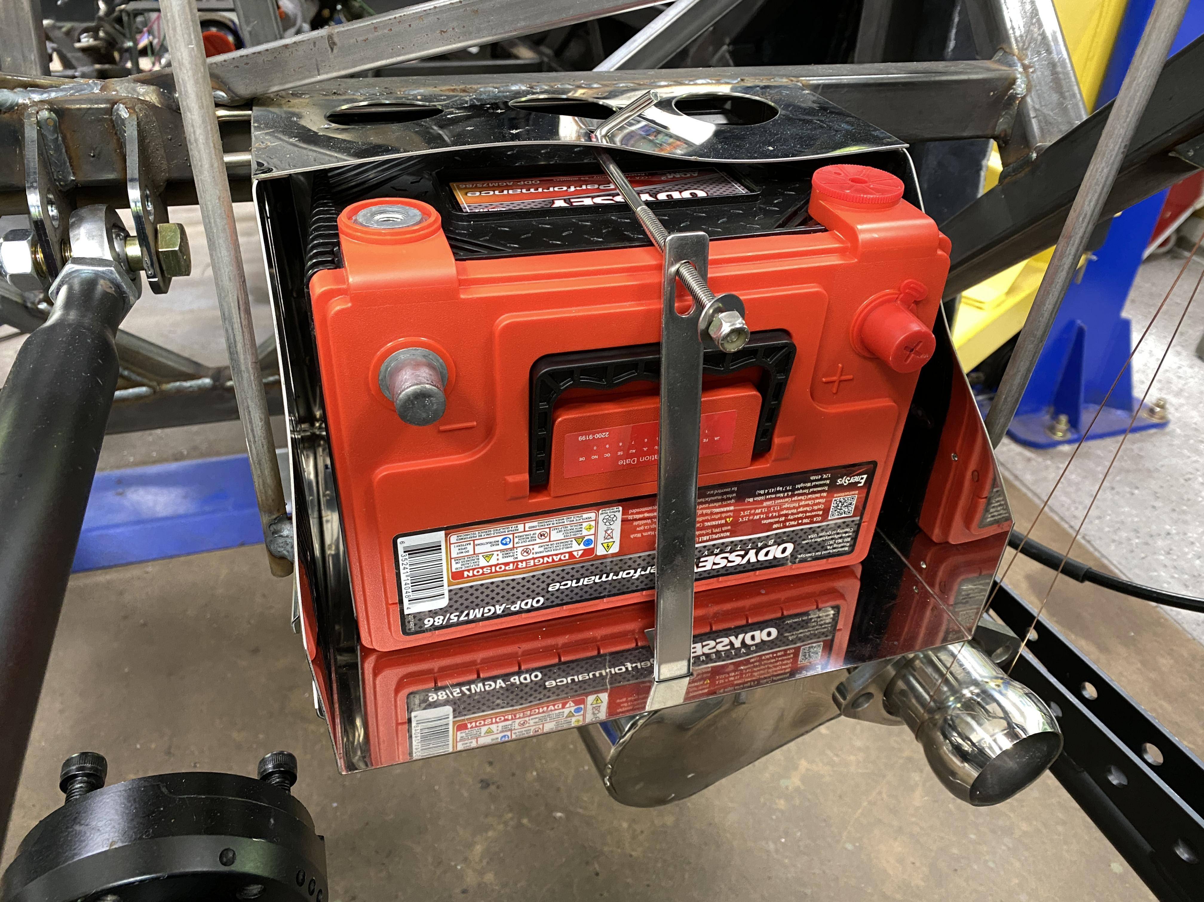
Lastly, I mounted a remote battery box in location above the right rear muffler, passenger side. It will hold a larger AGM battery that has two sets of connection terminals. Also, being an AGM style battery, I can lay it on it's side. I can get the battery in and out of the box from the bottom under the truck and the top if I remove the bed... so good to go. I'll add insulation between the muffler and the battery box. Regardless, heat won't be an issue as this location is a lot cooler then most cars today that have the battery location in the engine compartment. I welded the battery box to the frame and added extra support braces.

I'll continue with further mockup and fabrication. I'll also add an engine oil cooler/radiator & fan above the gas tank. I'm waiting for a few parts from Summit Racing before I can proceed. The entire oil system will include the remote oil filter, an oil thermostat valve that will open when the oil reached a set temp to divert oil to the cooler. This way, the oil isn't being cooled when it shouldn't be, i.e., the oil temp is below the setting in the thermostat valve.
Stay tuned.
Thx Mark
-
Post Thanks / Like - 0 Thanks, 2 Likes
-
Senior Member
Charcoal gas vapor canister installed
A quick simple update here today. I started the brake/clutch pedal and master cylinders yesterday... nothing much there to report or take pictures of.
Regarding the gas vapor canister I made and documented earlier in this thread.... I got it installed. I had this old bracket from a previous build for some other canister that fit the vapor canister perfectly. So I made two mounting tabs and welded the tabs to the frame by the battery box. This vapor canister will be connected to the gas tank's vapor vent and should prevent any gas smell in the garage.


I'll continue working the brake systems.... brake lines, clutch line, brake bias valve, electric emergency brake, etc. I'll document all as I can.
More to come:
thx Mark
-
Post Thanks / Like - 0 Thanks, 1 Likes
-
Senior Member

Dropping dimes with the wire feed! Very nice! Subscribed!
Higgy
MK4 #11012 picked up 04/16/24
351W, 3 link, single roll bar
MK4 #10616 picked up 4/10/23
302w, 4 link, 17's, dual roll bar SOLD
MK4 #9759 picked up on 4/3/19
351C, 3 link, 17's, dual roll bars SOLD
-
Post Thanks / Like - 1 Thanks, 0 Likes
-
Senior Member
Help needed on Coyote clutch switch!
OK, need some advise/help on the Coyote clutch switch that comes with the Coyote ECU pack and the FF Coyote install kit.
In the attached picture below, I added a yellow arrow pointing to the Coyote clutch switch and the FF mounting bracket for the clutch switch. The FF manual shows how to install as I have pictured, but nothing I can see on what engages the Coyote clutch switch.
So, I'm looking for any thoughts or direction on how does it work?
Thx Mark

-
Senior Member
Originally Posted by
mkassab
OK, need some advise/help on the Coyote clutch switch that comes with the Coyote ECU pack and the FF Coyote install kit.
In the attached picture below, I added a yellow arrow pointing to the Coyote clutch switch and the FF mounting bracket for the clutch switch. The FF manual shows how to install as I have pictured, but nothing I can see on what engages the Coyote clutch switch.
So, I'm looking for any thoughts or direction on how does it work?
Thx Mark
I found out what I needed.... I'll document what I did soon
Thx Mark


 Thanks:
  Likes:


 Reply With Quote


