-
Member

-
Post Thanks / Like - 1 Thanks, 4 Likes
-
Member
-
Post Thanks / Like - 0 Thanks, 1 Likes
-
Member
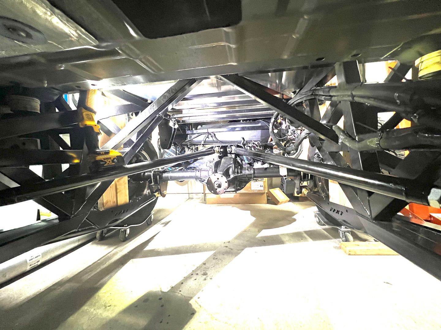
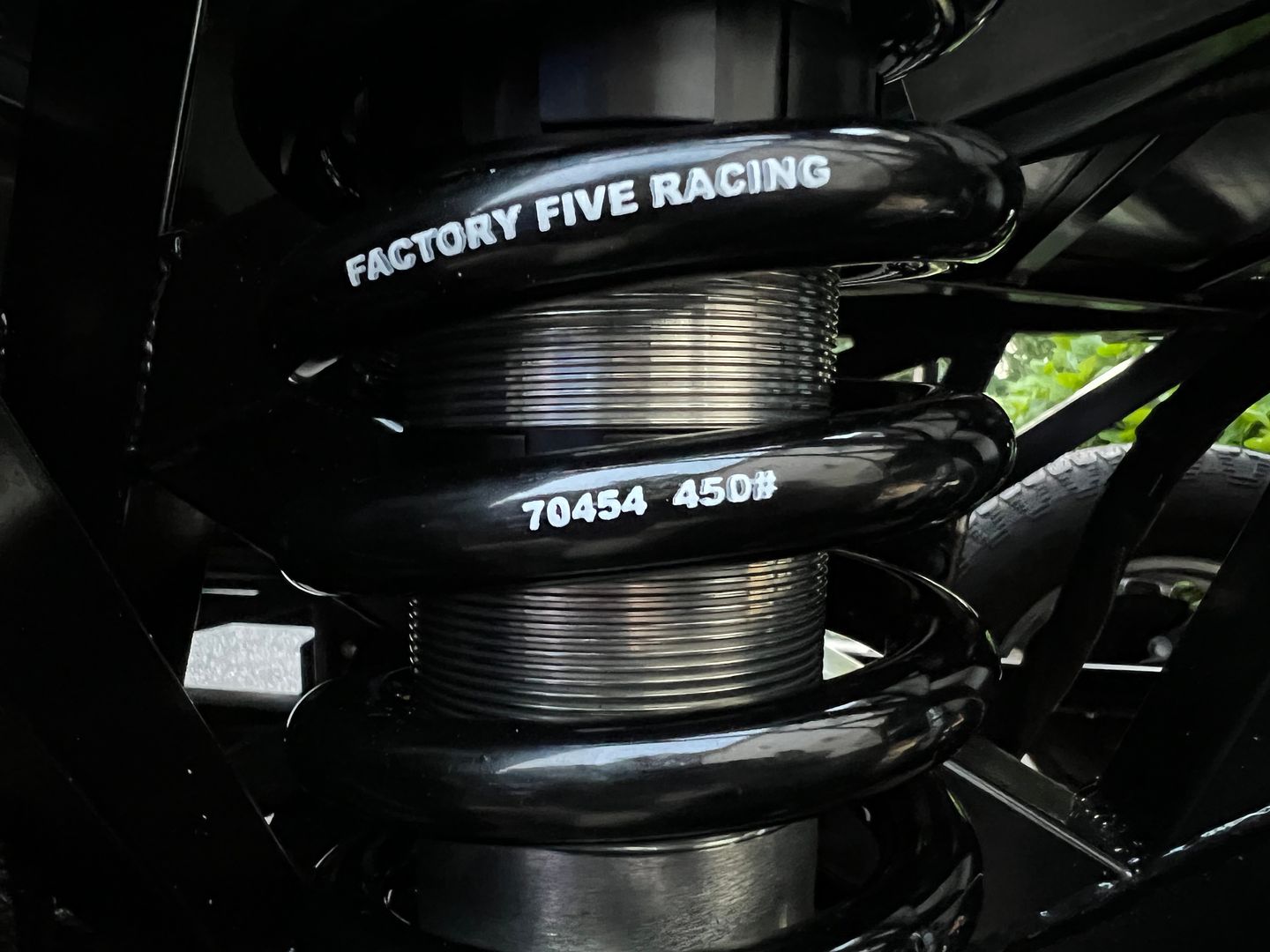
In order to build a more capable truck than anything you get from a major manufacturer, it’s necessary to start over with a new frame. The frame needs to prioritize articulation as well as have the ability to take advantage of a race quality off road suspension.
One feature that takes the truck to the next level is a second shock called a bypass shock. Here is an example
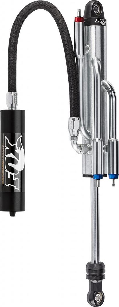
Using a shock like this you can tune each portion of the travel of the shock.
Each section of the travel has its own damping adjustment that is completely unrelated to the travel before or after.
Many traditional mono tube shocks are limited by a common set of valves that limit how drastically you can adjust travel throughout the stroke. Especially without physically opening the damper and changing valve packs. Using both a standard mono tube shock and a bypass shock at the same time it’s possible to blend the best of both worlds. The mono tube provides a fixed damping curve and the bypass shock provides a stepped curve where it’s possible to tune each section of the stroke. The bypass shocks allows adjustment of each portion of the stroke with adjustment knobs outside the shock. Changes can be made quickly on the fly for each step of the travel.
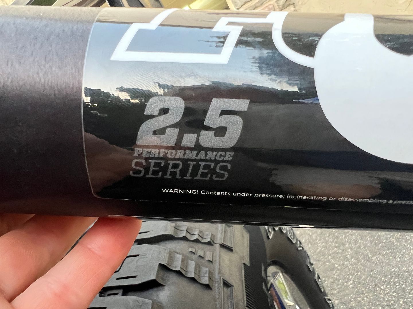
Of course if you go this route ( as I will) it’s necessary to re tune the shock sent with the basic kit. Since the bypass shock will do part of the damping work, it’s necessary to remove some damping from the stock factory five tuned Fox Shock. Luckily the Fox 2.5 dual compression adjustable shock is fully rebuildable and tune able using basic hand tools and a compressed nitrogen cylinder to recharge the shock.
I plan to both test the performance of the standard kit built on the Gen 14 F150 as well as build and test the next level performance afforded by a bypass shock.
Finally the frame will accept air bump stops as well.
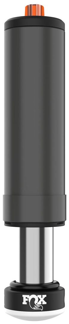
Air bump stops are yet another shock to help you control that last bit of travel before the shock hits bottom.
The great thing is no matter where you want this truck to be from a performance standpoint the frame is already built to accept the upgrade.
I can’t wait to start testing!
Last edited by kabacj; 07-28-2023 at 09:17 AM.
Reason: Clarification
XTF #2
build start date June 19 2023
GTM # 344
Build Start December 2010
First track day April 2013
-
Post Thanks / Like - 0 Thanks, 1 Likes
-
Member
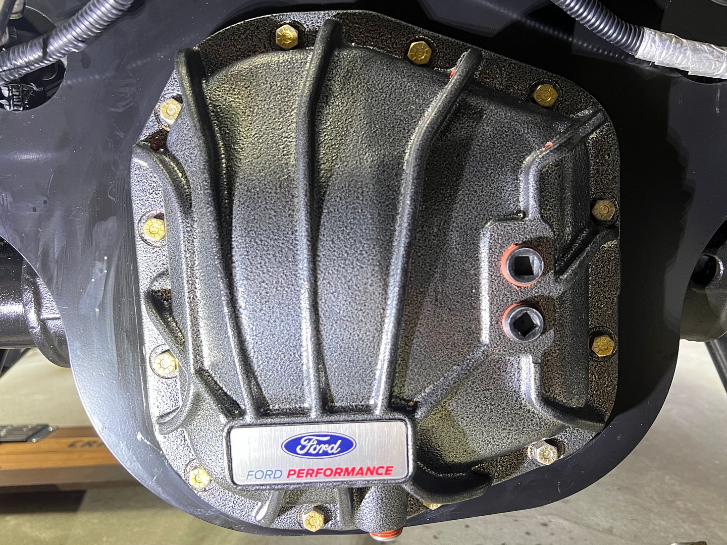
I solved a mystery from a few weeks ago. I was looking for an M9-1 bolt for the Ford 9.75 inch differential housing. Using my tap and die set I sized the bolt to be 9mm but I could not find a thread pitch that matched and I guessed the thread pitch was 1MM. Of course there are no 9M-1 bolts to be had anywhere except a few titanium bolts listed on Amazon.
Turns out my problem was I didnt have the tap and die that matched the bolt.
Somehow I have survived using my tap and die method of sizing nuts and bolts for many years, but this project has stumped me a few times.
I found a good solution.
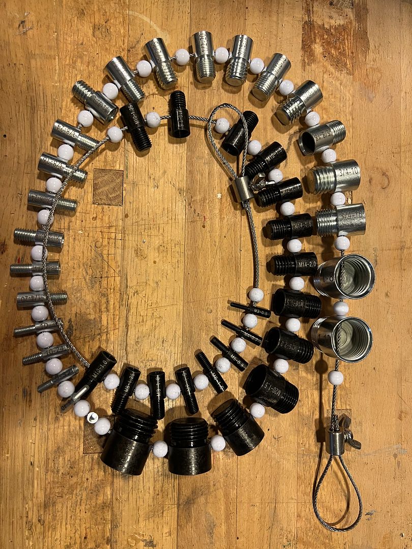
I thought I had every tool under the sun, but this one really helps. Now I know the size of the bolts that go into the Ford 9.75 differential cover.
5/16 - 18.. That was easy!

XTF #2
build start date June 19 2023
GTM # 344
Build Start December 2010
First track day April 2013
-
Post Thanks / Like - 0 Thanks, 2 Likes
-
Member
-
Post Thanks / Like - 0 Thanks, 1 Likes
-
Member
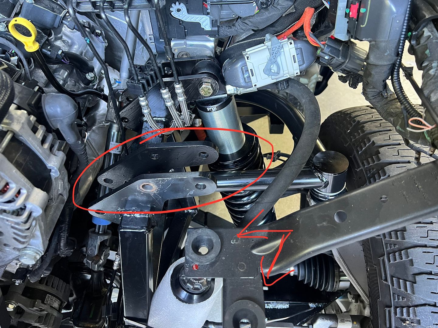
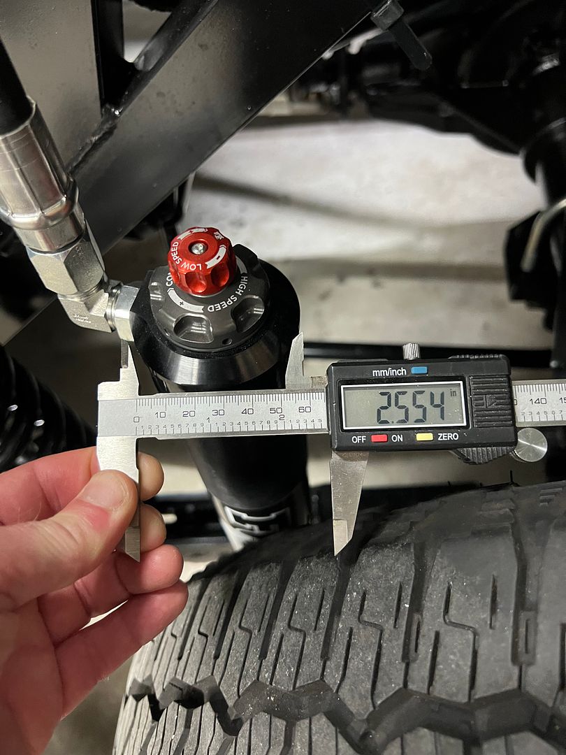
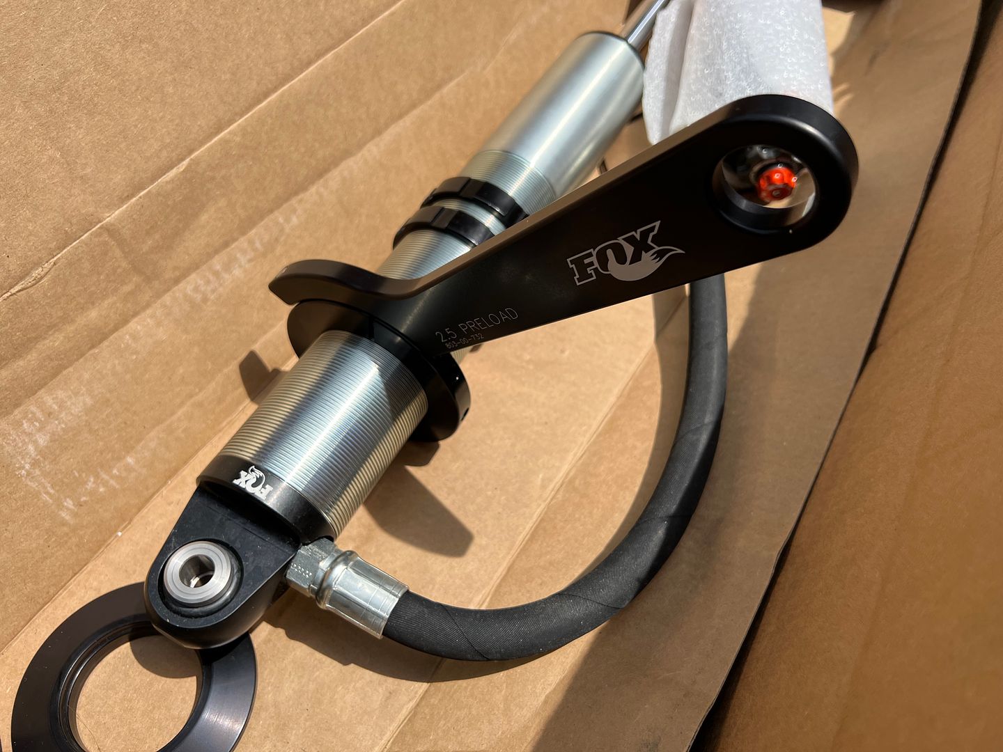
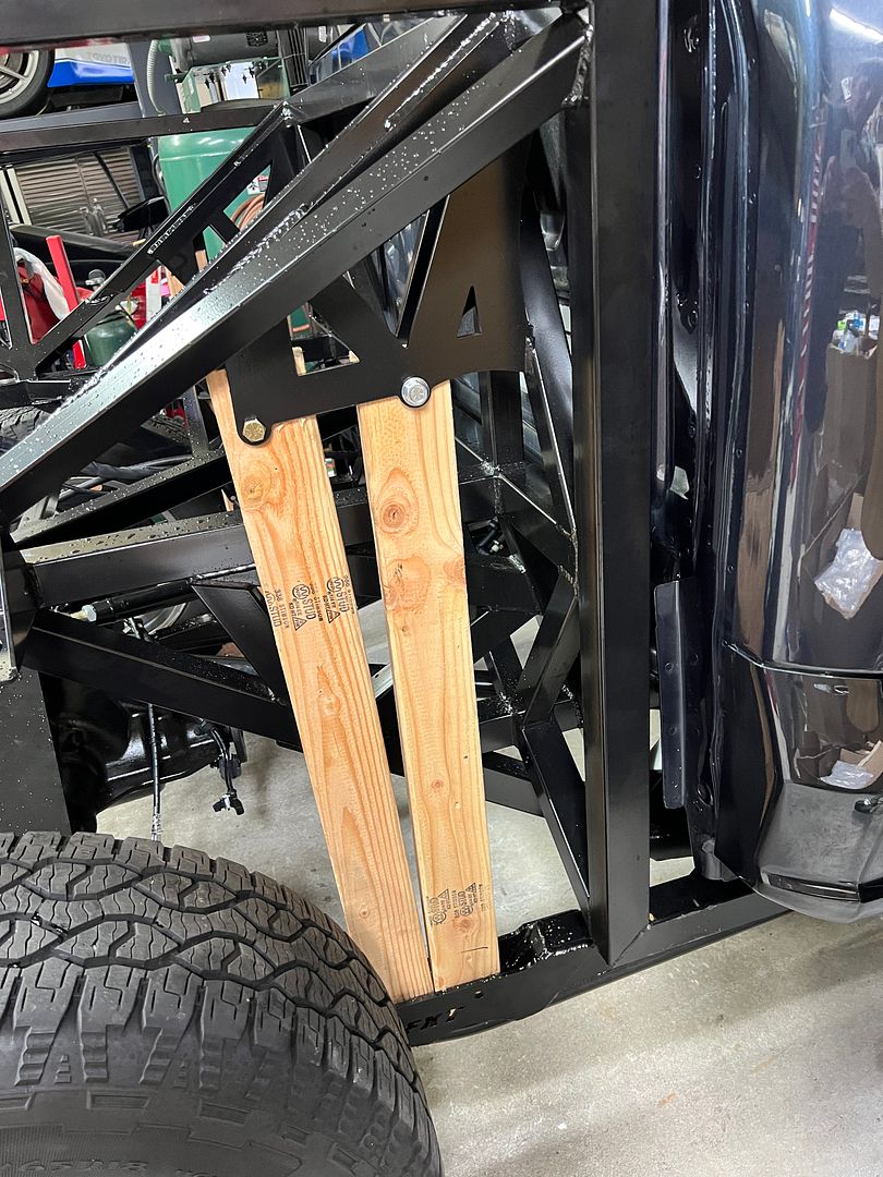
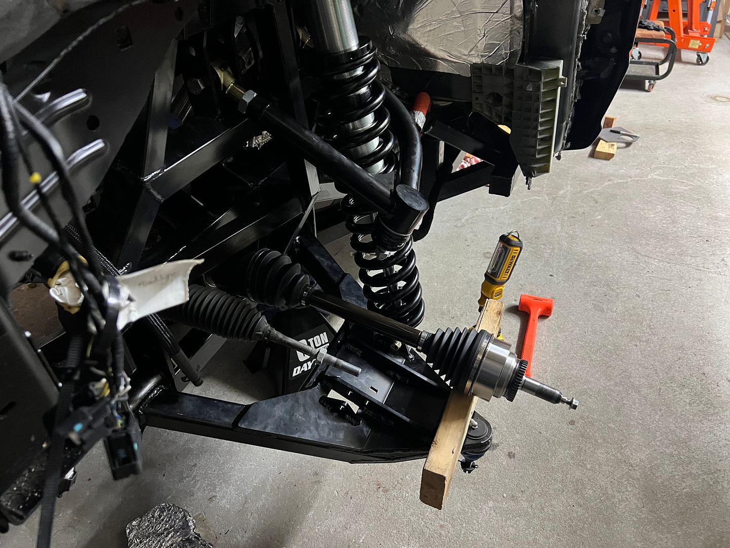
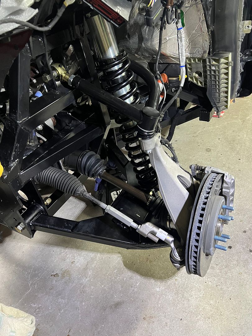
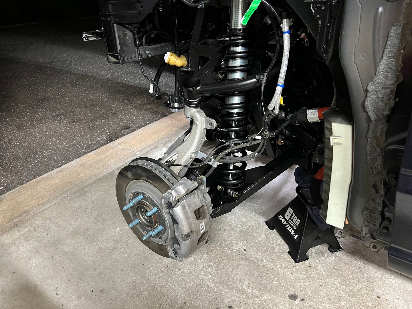
Since I plan to do lots of testing and adjusting of the suspension I figured i need to outfit myself with the proper tools. One tool thats very helpful is a preload adjuster.
Here is the preload adjuster aka spanner wrench from FOX. Note the part number. 803-00-832 this preload adjuster fits the Fox 2.5 DSC damper included with the kit.

The adjuster attaches to the top collar on the shock like this allowing you to crank down on the spring increasing or decreasing the static ride height. Right now I just have the adjustments at zero pre load to see where everything ends up.
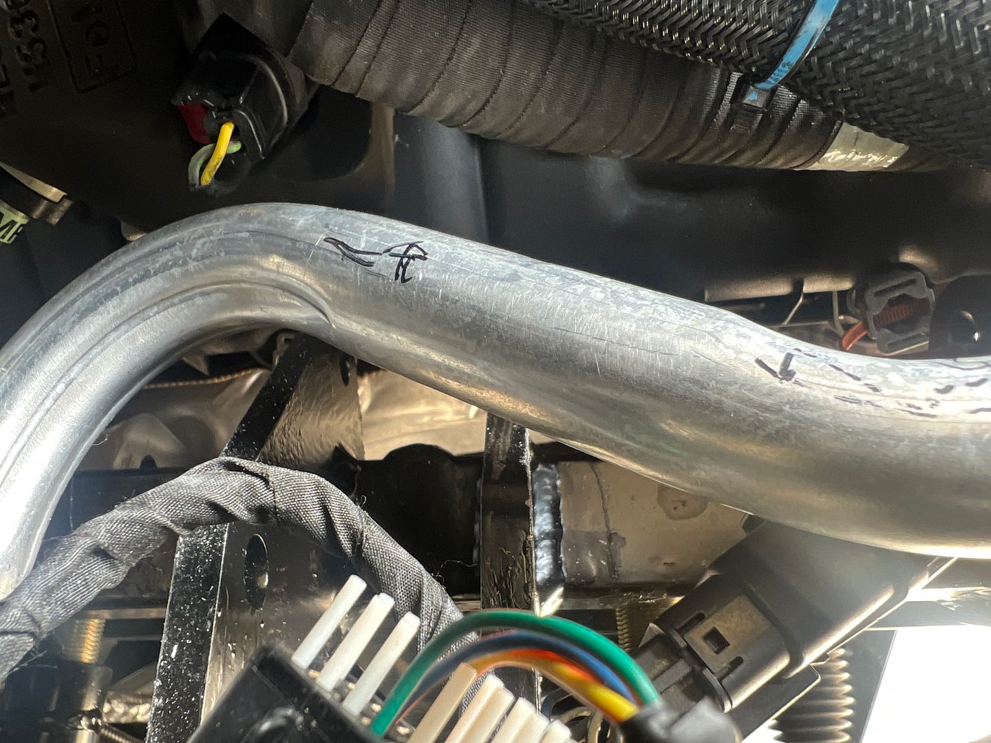
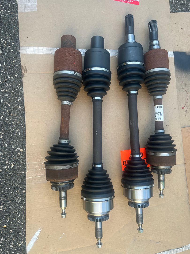
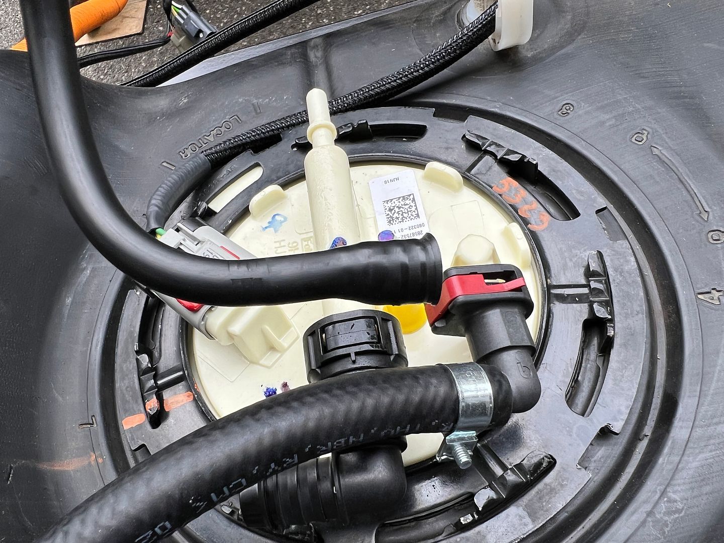
The other thing needed for the next step is the CV axles. Factory Five had longer CV axles made to allow for both wider track as well as more travel. You can see the increase in length on the Factory Five CV axle compared to the ones removed from the stock F150.
Last edited by kabacj; 07-31-2023 at 07:11 AM.
Reason: Typo
XTF #2
build start date June 19 2023
GTM # 344
Build Start December 2010
First track day April 2013
-
Post Thanks / Like - 0 Thanks, 1 Likes
-
East Coast Speed Machines

You will need to crank down on the fronts at least to have 4-5 inches at the top (like you have it) with the front spring installed
FFR 1879, Blown DSS 306,REDLINE management, VeryCoolParts Tuned 460RWHP
FFR 818S, The Flash, Chassis #5, 2.0L, LSD, Electromotive TEC-S, VCP Tuned, 278RWHP 265 RWTQ
FFR 6651, Green Lantern, 408W Crate, Hellion 66mm Turbo, JGS Waste gate / Blowoff valve, Tec-GT management, VCP Tuned, 575 RWHP, 690 RWTQ
FFR 8335, Black Mamba, 289 FIA CSX 2001 tribute car, 347, 48 IDA webers, VCP Tuned, 311 RWHP 386 RWTQ, 3-link, Trigo's
FFR 0004, Gen 3 , Hawk Coupe, Coyote twin turbo, 683 RWHP 559 RWTQ, IRS, VCP Tuned. "not too shabby"
US ARMY Maintenance Test Pilot (CW4 Retired)
-
Post Thanks / Like - 2 Thanks, 1 Likes
-
Member
Thanks for the info Erik.
Your videos are also helpful as I can see how things are setup in the GEN 13 F150 vs Gen 14. That of course and a lesson on how to fit two turbos into barely enough space.
XTF #2
build start date June 19 2023
GTM # 344
Build Start December 2010
First track day April 2013
-
Member
-
Member
-
Post Thanks / Like - 1 Thanks, 0 Likes
-
Member
-
I'm enjoying following along with your and Erik's builds. As you identify these differences, is Factory Five making any changes to the parts they supply with the kits, or is that left to the builder?
-
Senior Member

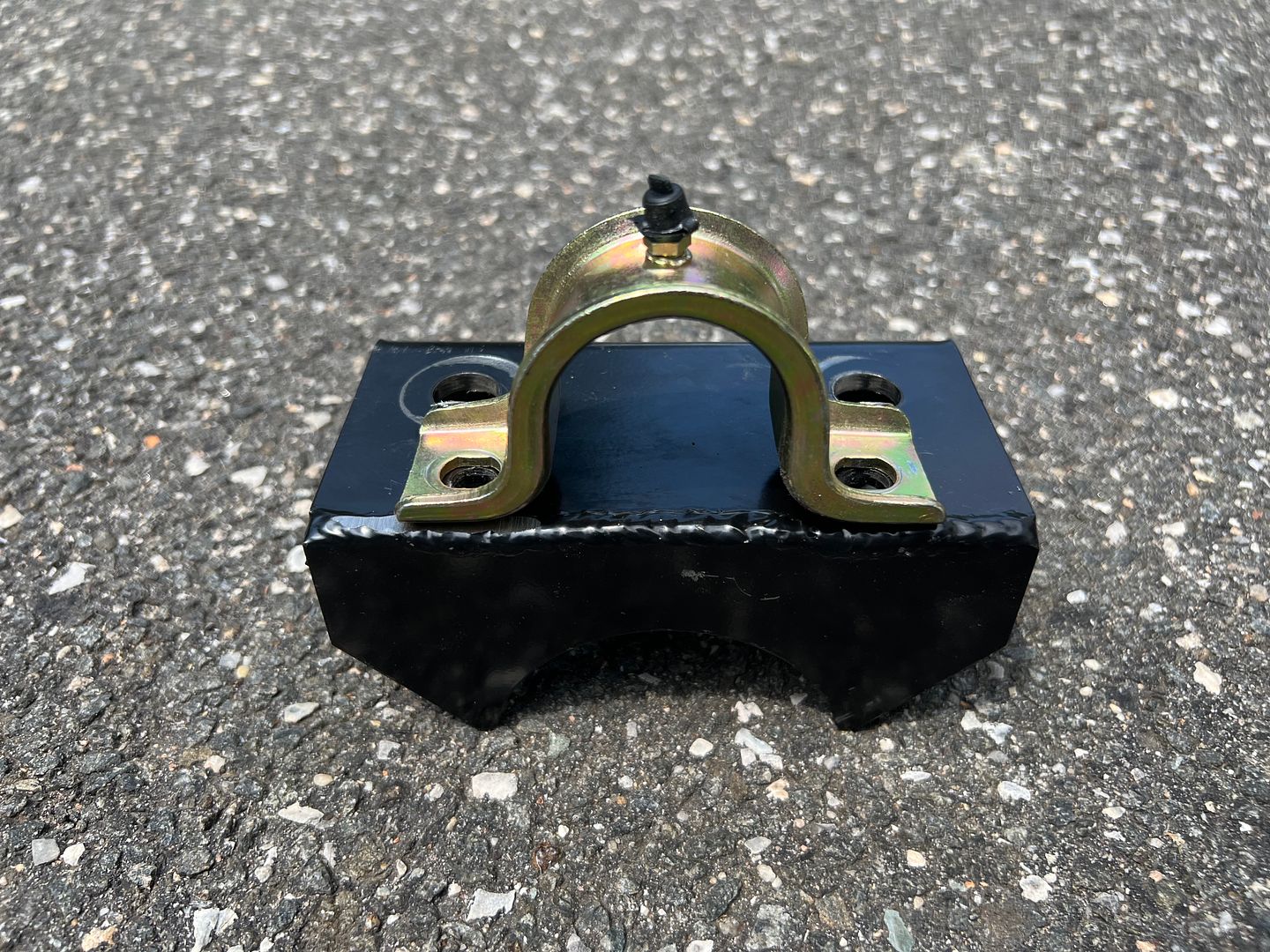
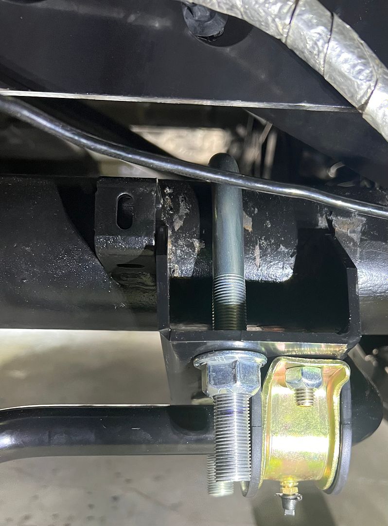
Is there anything that prevents the anti-rollbar brackets from rotating around the axle other than U-bolt tension and friction? It looks like there is no physical geometry that would stop this behavior - but I don't know if it's even a concern based on the loading of the anti-rollbar. Are there any shear forces on it during activation that would cause it to want to twist around the axle, or is it strictly "vertical" in line with the axle?
Thanks for the great build thread!
818C chassis #546. Ordered 8/14/18, picked up 10/6/18. First start 01/16/2021!
Donor: 2006 WRX wagon, 108k miles.
Options: Chassis powder coat, CF street splitter, rockers, diffuser, and spoiler, polished shift knob, adjustable rear lower lateral control arms, vinyl padded dash/door, complete carpet set, battery cut-off switch, wiper kit, aluminum shifter assembly, complete CV axles, harness bar mount, matte gunmetal wheels.
-
Member

Originally Posted by
Papa

I'm enjoying following along with your and Erik's builds. As you identify these differences, is Factory Five making any changes to the parts they supply with the kits, or is that left to the builder?
Hey Papa.
Yes Factory Five are making changes to the kit to accommodate the GEN 14 F150. The idea is the builder will have a list if items to purchase from FORD or from a junk yard to accommodate things like the body lines and trim pieces. Bottom line you as a builder will know exactly what is different when you compare the cost and effort of building the XTF starting from a Gen 13 or Gen 14 F150.
Thanks for following along and asking questions!
XTF #2
build start date June 19 2023
GTM # 344
Build Start December 2010
First track day April 2013
-
Member
Originally Posted by
octobersknight
Is there anything that prevents the anti-rollbar brackets from rotating around the axle other than U-bolt tension and friction? It looks like there is no physical geometry that would stop this behavior - but I don't know if it's even a concern based on the loading of the anti-rollbar. Are there any shear forces on it during activation that would cause it to want to twist around the axle, or is it strictly "vertical" in line with the axle?
Thanks for the great build thread!
Hey Octobersknight
The forces on the bushings are longitudinal twisting.imagine the anti roll bar is not bent around the differential but simply a squared off U shape. As one perpendicular arm of the square U goes up up it twists the longitudinal bar. The bar that goes width wise across the truck experiences spiral twisting forces

There is little force attempting to move the anti roll bar brackets around the axle. Sure there is some but those U bolts clamp down pretty well.
Theory is one thing, testing is another. We are going to really run this truck through its paces to see what happens.
Last edited by kabacj; 08-03-2023 at 08:22 AM.
Reason: Typo
XTF #2
build start date June 19 2023
GTM # 344
Build Start December 2010
First track day April 2013
-
Member
The other big difference between Gen 13 (2015 to 2020) and Gen 14 (2021 to 2023) is the headlights and taillights.
I am torn between keeping the gen 13 look and changing the truck to look like a gen 14.
There are two major concerns. First is the wiring and integration with the computer systems in the truck. The tail lights have the blind spot detection system built into the taillight housing as well as possibly some integration into the trailer backup assist gizmos. The headlights are LED and have the computer controls and low amperage wiring associated with those.
Of course the headlights and taillights are a different shape on the gen 14 compared to the gen 13 the XTF was based on.
I have a few ideas on how i can solve the bodywork. I took some 3d scans of the headlights and tail lights

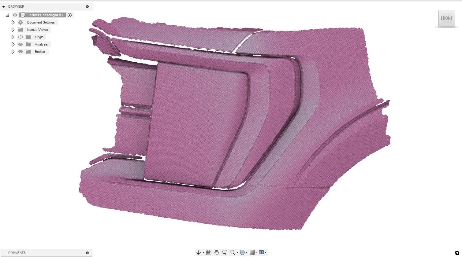
I could mill out or 3D print a mould that looks like the gen 14 bodywork, make a fiberglass part and then graft it into the factory five bodywork. Im not sure what will be fastest and most accurate.
XTF #2
build start date June 19 2023
GTM # 344
Build Start December 2010
First track day April 2013
-
The Gen14 BCM and completely different from the Gen13, I suspect you will have a headache if you try to use Gen13 lights, although you could probably reach out to one of the companies that makes lights and confirm (morimoto, diode dynamics). If your mill is big enough I would cut a mold from sheets of 2" pink foam sheets glued together. It is much easier to sand smooth the foam than 3D prints to get out the layer lines. Also a print that big and uniquely shaped will require quite a bit of supports.
-
Member
Originally Posted by
Ajzride
The Gen14 BCM and completely different from the Gen13, I suspect you will have a headache if you try to use Gen13 lights, although you could probably reach out to one of the companies that makes lights and confirm (morimoto, diode dynamics). If your mill is big enough I would cut a mold from sheets of 2" pink foam sheets glued together. It is much easier to sand smooth the foam than 3D prints to get out the layer lines. Also a print that big and uniquely shaped will require quite a bit of supports.
Hi Ajzride, I suspect that you are right about the lights. I tried a set of cheaper replacement gen 13 tail lights
and both the plugs, pinout, and wiring were different. Here is the Gen 14 pinout.
_IMG_9912.png?width=1920&height=1080&fit=bounds)
and this is the gen 13 pinout with the Blind spot detection module plug as well.
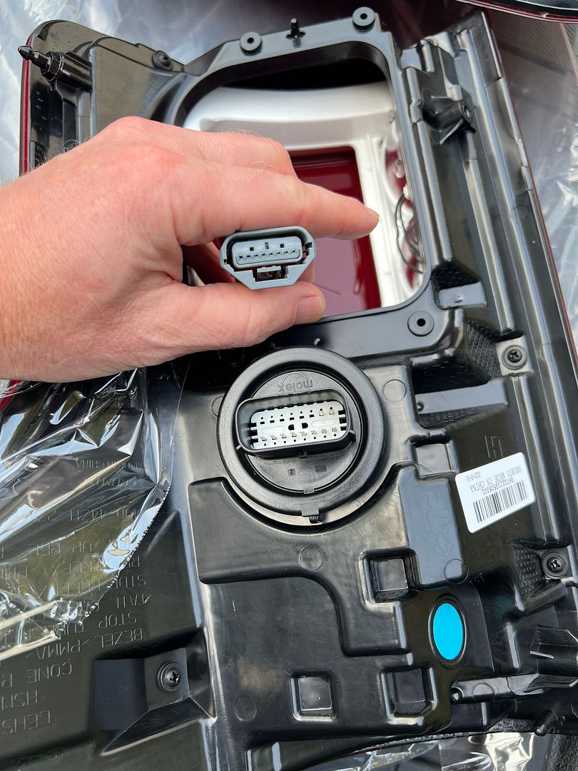
If i go with gen 13 lights, i will probably need to disassemble the gen 14 lights and rebuild them in the gen 13 housings. Seems like a lot of work.
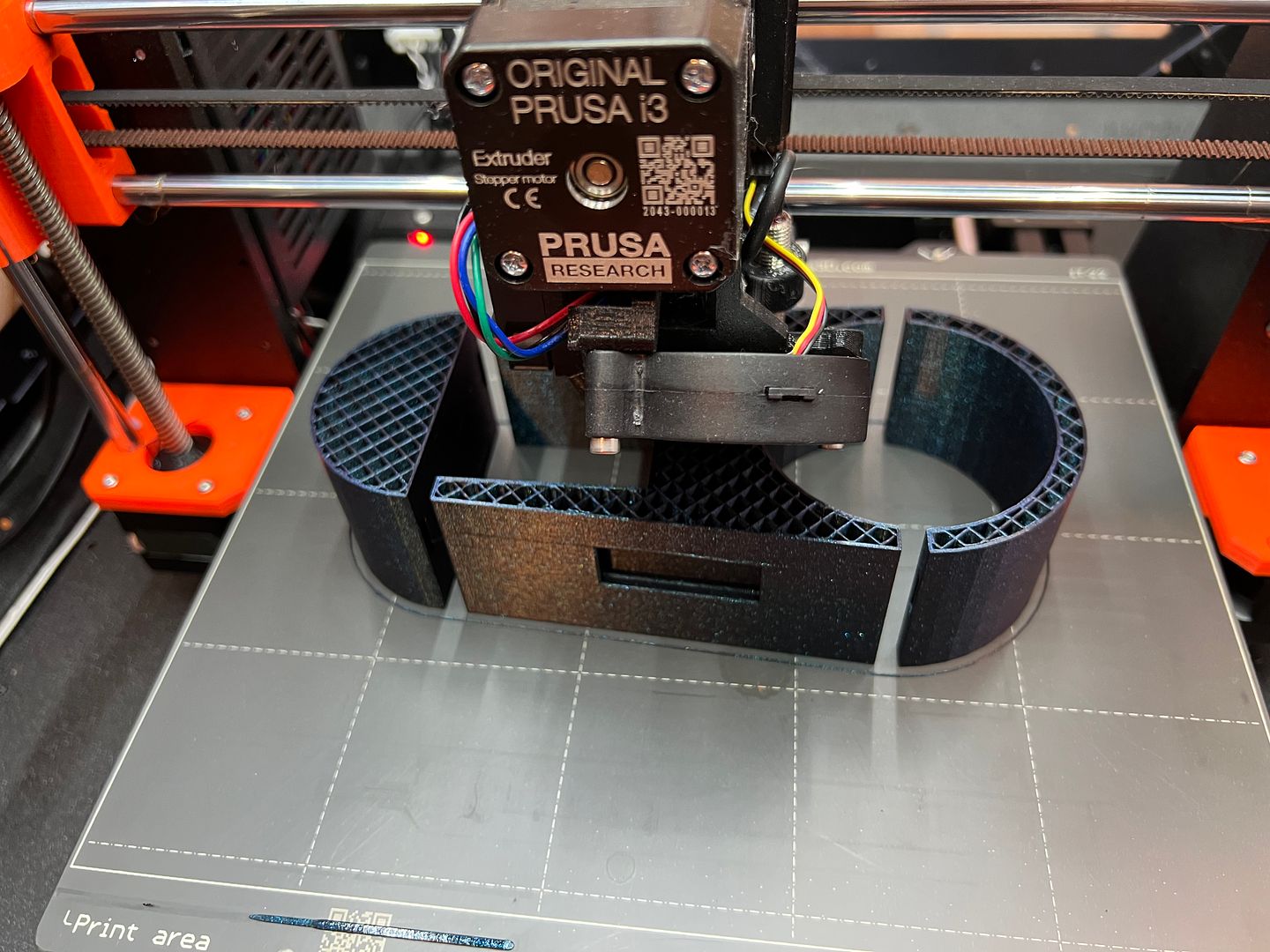
Regarding the 3d print vs pink foam. I was considering a multi piece 3d print to make a mold for the fiberglass and yes its going to be a complex print with lots of supports, but printing is usually easer to setup than milling although the prints will take a long time.
I even thought about making a pink foam positive mold where the foam would be a very slightly smaller scaled version of the finished part. Cover that foam with fiberglass and epoxy resin as polyester resin will melt it, Then mill the cured fiberglass to the finished shape. maybe that's more work than its worth, but i will not need to worry about draft angles so the part will release from a negative mold.
Thank you for the feedback and ideas.
XTF #2
build start date June 19 2023
GTM # 344
Build Start December 2010
First track day April 2013
-
Member
MAJOR mile stones this weekend.
First start and the truck moved under its own power and stopped!!
Of course I press the start button for the first start and the battery is almost dead. Ha. But 5 min on the battery booster it fired right up.
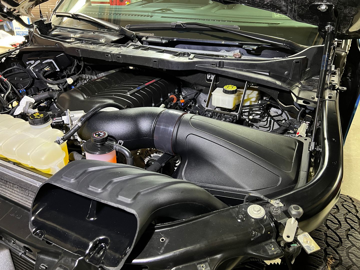
One of the amazing things about this Ford Performance (whipple supercharger) install is that you dont flash the ECU. You simply put in the hardware and fire it up! That was a bit scary to be honest. The ECU quickly learns the fuel air mixture and you are good to go. Pretty amazing really. No smell of un burnt fuel. No bad habits noticed so far. I really cant believe it was that easy to add so much hp. The super charger kit still comes with the Whipple tuner and OBD2 connector so you can monitor the system as well as make modifications in the future. Very nice.
XTF #2
build start date June 19 2023
GTM # 344
Build Start December 2010
First track day April 2013
-
Post Thanks / Like - 0 Thanks, 2 Likes
-
Member
-
Post Thanks / Like - 0 Thanks, 2 Likes
-
Member
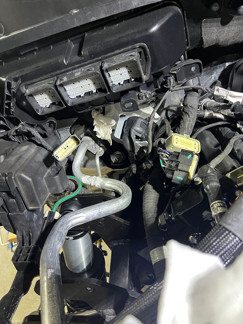
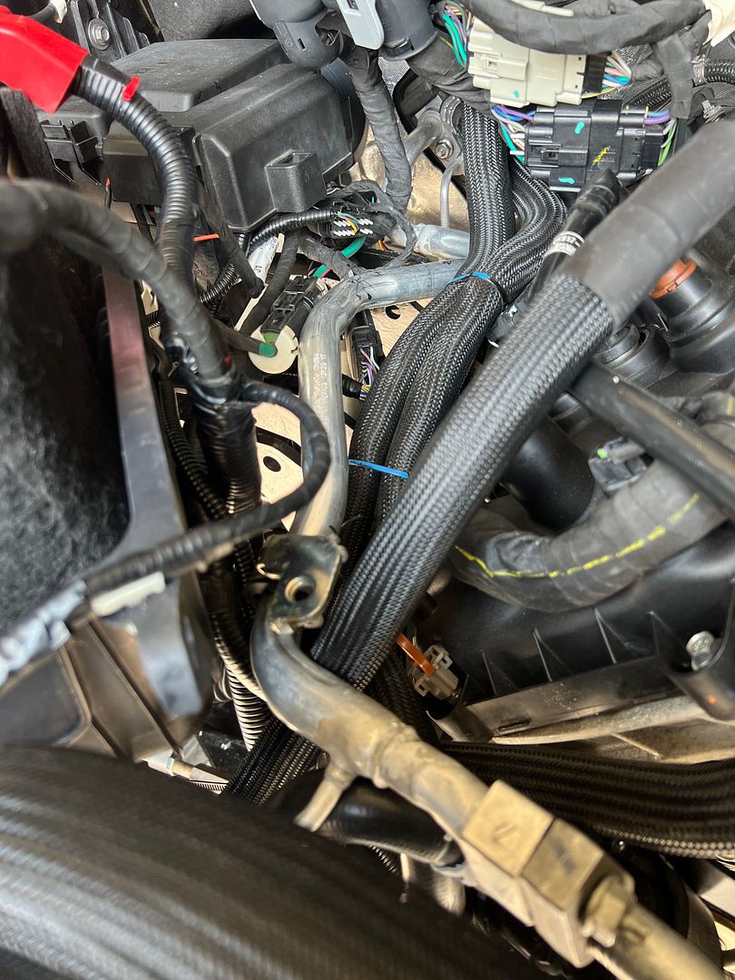
It is very different working on a rolling computer vs the mostly analog factory five cars we are used to. The computer has something to say about just about anything you do or touch.
Here is an example. I had not yet connected the braking system when I started the truck for the first time. Of course to start the truck that means connecting the battery. Once the battery is connected the truck immediately starts complaining about brake fluid levels, the fact that the braking system is inoperable. Of course the accident avoidance system cant work because the pre brake assist cant work so it complains about that.
Ok no problem (OK,OK,OK) to all the codes. Then this is the best, The truck immediately puts on the electric parking brakes and refuses to take them off. The buttons don't work!
Of course this is probably a good safety measure. If you don't have hydraulic brakes its probably not good to move the truck. Keep the electric brakes on.
But I want to move the truck. Nope you cant.
Well F150 computer I know how to fix you. Ill just unplug your connection to the electric brakes. Lets see how you deal with that.
Well I won that battle. Now I can push the truck.
OK F150, Im going to move you wether you like it or not. Ill just put the truck in neutral. Nope you cant. The gear shifter is controlled by the computer. It isnt physically connected to anything. Human, you can move the gear shifter all you want . We are in park.
OK F150, luckily the ford engineers thought of this and have a way to take the truck out of park even if the computer is dead.
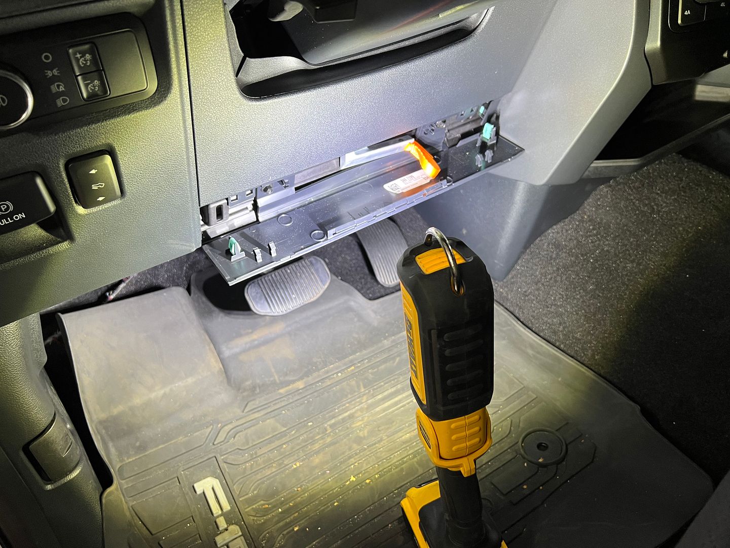
Pull this little orange tab and we can physically take the transmission out of park via a cable connected to the transmission.
NOW i can move the truck. Wow, that was a new experience.
When computers take over the world, at least you will know that you will be able to drive your factory five Cobra, hot rod, coupe, GTM, hot rod pickup, or 818. Your Factory Five XTF
the computers own that one.
XTF #2
build start date June 19 2023
GTM # 344
Build Start December 2010
First track day April 2013
-
Post Thanks / Like - 0 Thanks, 3 Likes
-
That shifter sucks. Mine had a switch go out so it couldn't tell where it was, and refused to shift out of park. The tow truck driver Ford sent didn't now about the orange tab, and he crawled under the truck and forced it into neutral. After Ford replaced the shifter they spent another 3 days cleaning all the codes brought on by forcing the transmission into neutral manually.
I wish Ford had just put in a knob like Dodge (or like they do in the escape), but their marketing team did a poll and truck drivers want a real shifter.....
Side Note: I have a mongoose cable if you find yourself needing to do firmware updates on the modules, I'd be happy to put it in the mail for you.
Last edited by Ajzride; 08-09-2023 at 07:37 AM.
-

Moderator

I work with computers for a living and that was a fun read - it's like debugging a car!
James
FFR33 #997 (Gen1 chassis, Gen2 body), license plate DRIVE IT says it all!
build thread
My build: 350SBC, TKO600, hardtop, no fenders/hood, 32 grill, 3 link, sway bars, 355/30r19
Previous cars: GTD40, Cobra, tubeframe 55 Chevy, 66 Nova, 56 F100
-
Member
Originally Posted by
Ajzride
After Ford replaced the shifter they spent another 3 days cleaning all the codes brought on by forcing the transmission into neutral manually.
Thanks for the offer for the computer interface cable Ajzride. Hopefully I will not need one.
Regarding he manual control of the shifter. When I was pulling the body off I had to disconnect the cable from the transmission to free the cab from the Ford frame.
I thought it was weird to have a cable going from the cab to the transmission without any way to control that cable that I was aware of. Only later when I researched putting the truck into neutral manually did I realize what the cable was for. The access door for the manual operation is well hidden .

XTF #2
build start date June 19 2023
GTM # 344
Build Start December 2010
First track day April 2013
-
Member
Originally Posted by
RoadRacer
I work with computers for a living and that was a fun read - it's like debugging a car!
Well to follow the theme of debugging a computer I challenge anyone to watch this video once and go into your truck and enable this mode.
While its definitely not user friendly, this procedure is helpful when you are building the XTF. For example the truck just fits in my garage. To move the truck 1/2 inch from the garage wall I can put it in flat tow mode and push it the last few inches.
XTF #2
build start date June 19 2023
GTM # 344
Build Start December 2010
First track day April 2013
-
Post Thanks / Like - 0 Thanks, 1 Likes
-
Member
-
Post Thanks / Like - 0 Thanks, 2 Likes
-
Member
-
Post Thanks / Like - 0 Thanks, 1 Likes
-
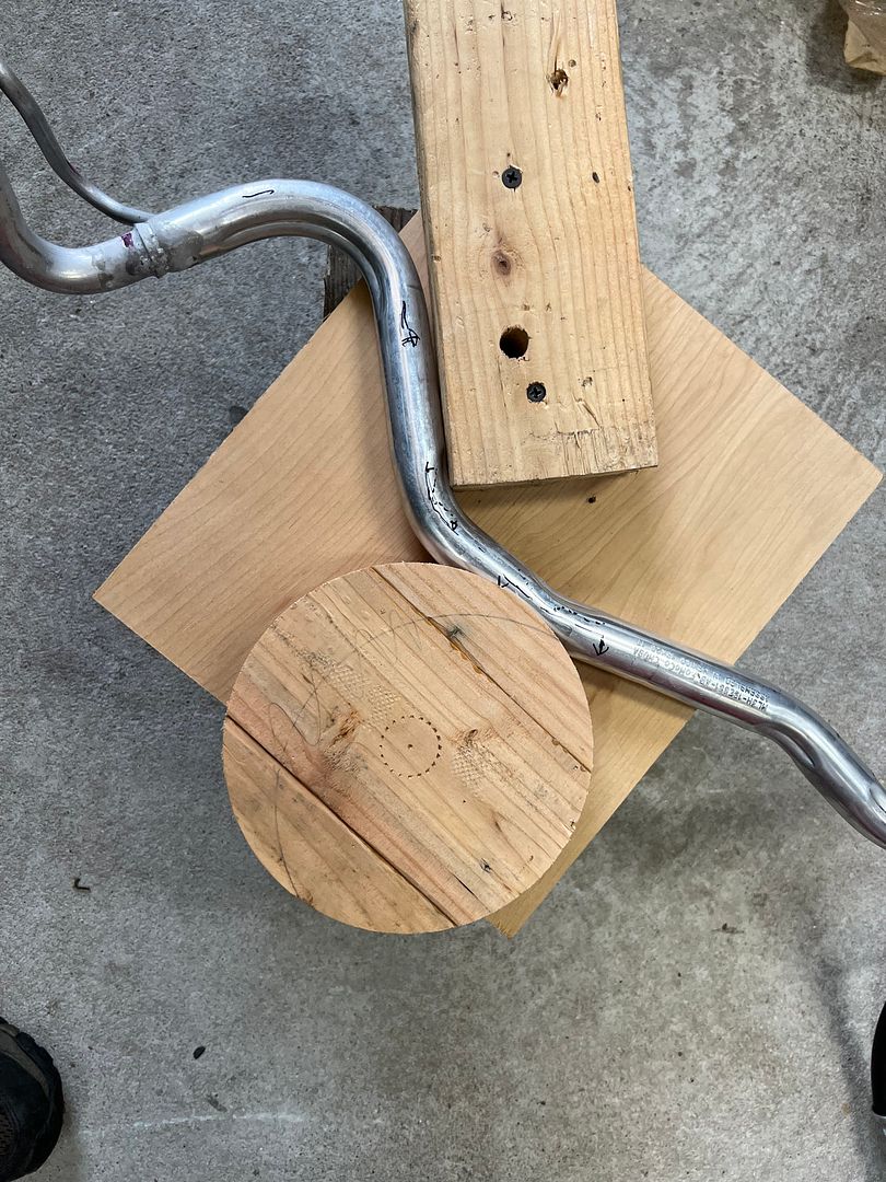
Not a waxer

Well done John! There is no forgiveness with aluminum tubing.
Jeff
-
Post Thanks / Like - 1 Thanks, 0 Likes
-
Senior Member

Kudos Kabacj
I had an Oak tree fall on my DD pick-up truck, totaling it out. Using the lemon/lemonade analogy, I made fixtures out of the Oak to press bends into 2 X 3 frame rails for a street rod. There was (wood) surface damage after one or two bends and steel sheet liners stopped that. I find it hard to dispose those "one time" solutions, they are like trophies.
jim
-
Post Thanks / Like - 1 Thanks, 0 Likes
-
Member
Originally Posted by
Jeff Kleiner
Well done John! There is no forgiveness with aluminum tubing.
Jeff
You know it Jeff! I walked away from this bend several times. One extra pull in frustration and its over. Lets see if it holds a vacuum, then we can celebrate.
XTF #2
build start date June 19 2023
GTM # 344
Build Start December 2010
First track day April 2013
-
Member
Originally Posted by
J R Jones
Kudos Kabacj
I had an Oak tree fall on my DD pick-up truck, totaling it out. Using the lemon/lemonade analogy, I made fixtures out of the Oak to press bends into 2 X 3 frame rails for a street rod. There was (wood) surface damage after one or two bends and steel sheet liners stopped that. I find it hard to dispose those "one time" solutions, they are like trophies.
jim
Wood is an excellent tool Jim as you know. Oak is especially useful and a beautiful material. There is nothing like taking a once living thing and making it into a new thing with a new purpose. Im glad to hear you were able give new life to the tree that killed your pickup. Better yet that tree helped give life to a new hotrod that produced carbon to grow more trees. Its the circle of life haha.
Talking about these one time tools. I also have a nice trophy collection of one time tools. I keep them just in case.
This wood is left over from same 2x4s I used to lift the body over the frame. The circle of life in my shop. 
John
XTF #2
build start date June 19 2023
GTM # 344
Build Start December 2010
First track day April 2013
-
Member
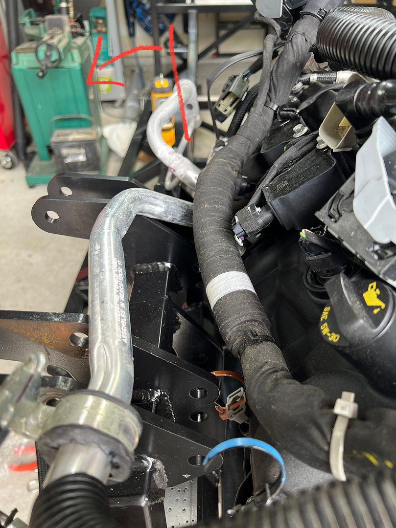
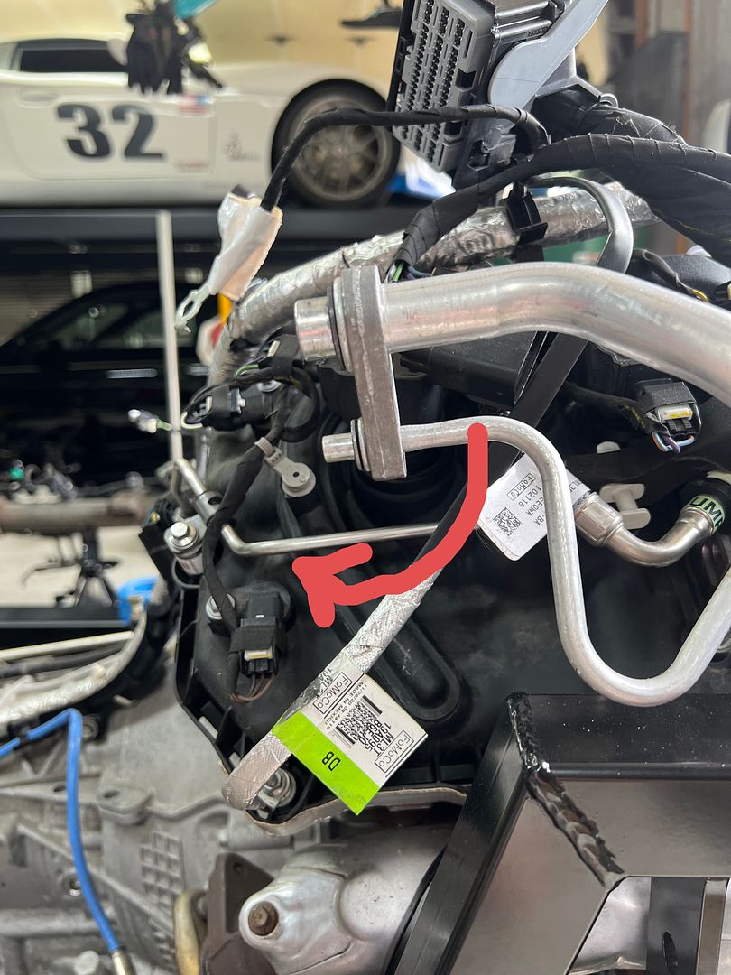
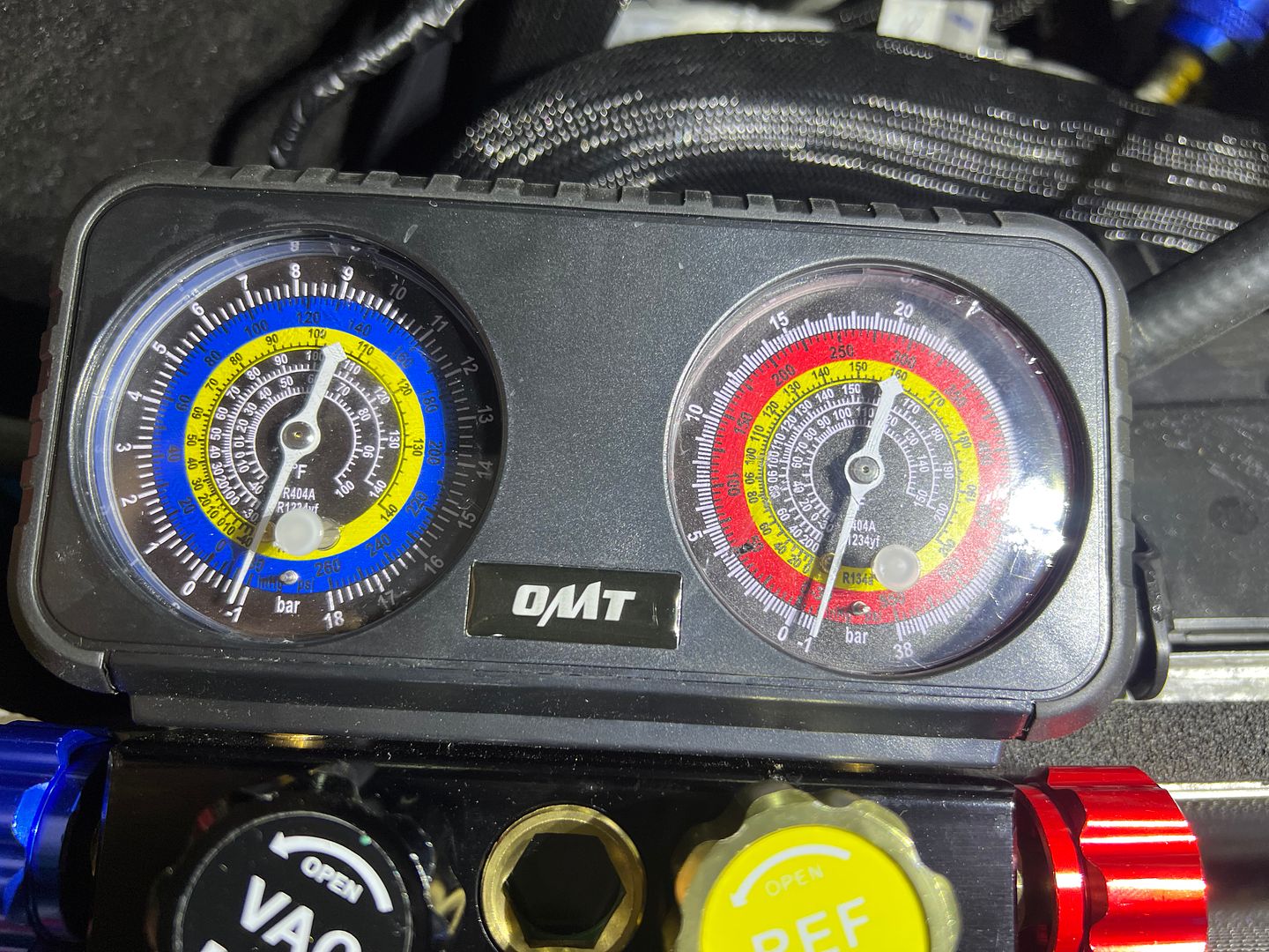
Well I think we can call the AC line bend experiment a success. I was able to pull a vacuum and hold it over night.
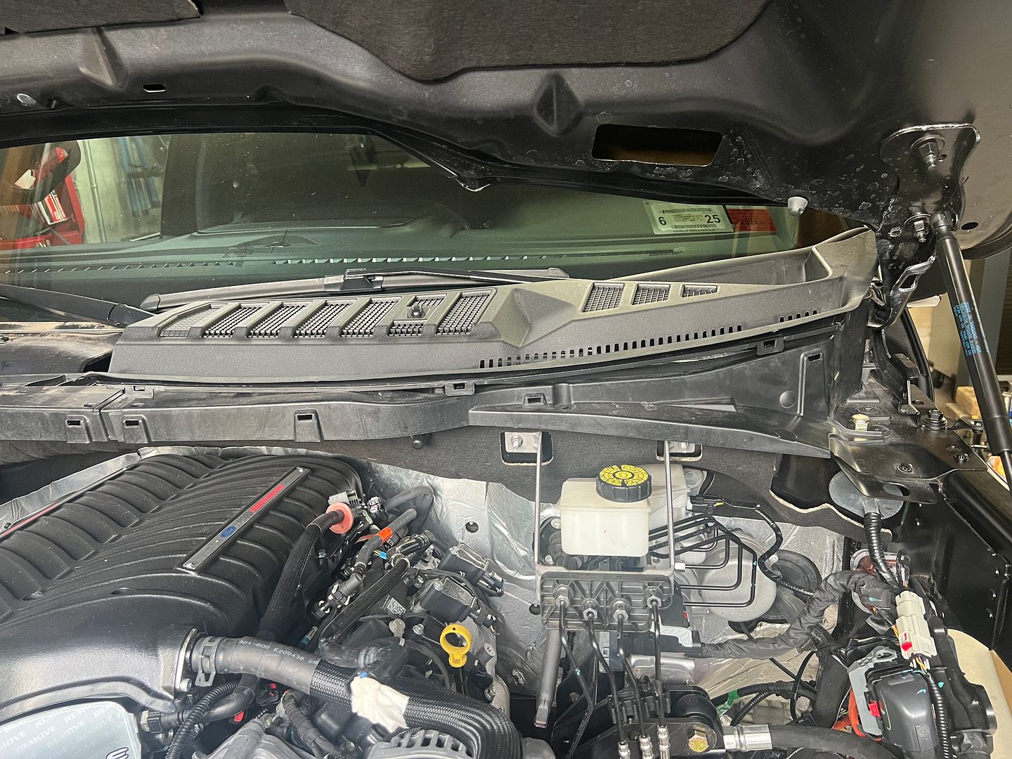
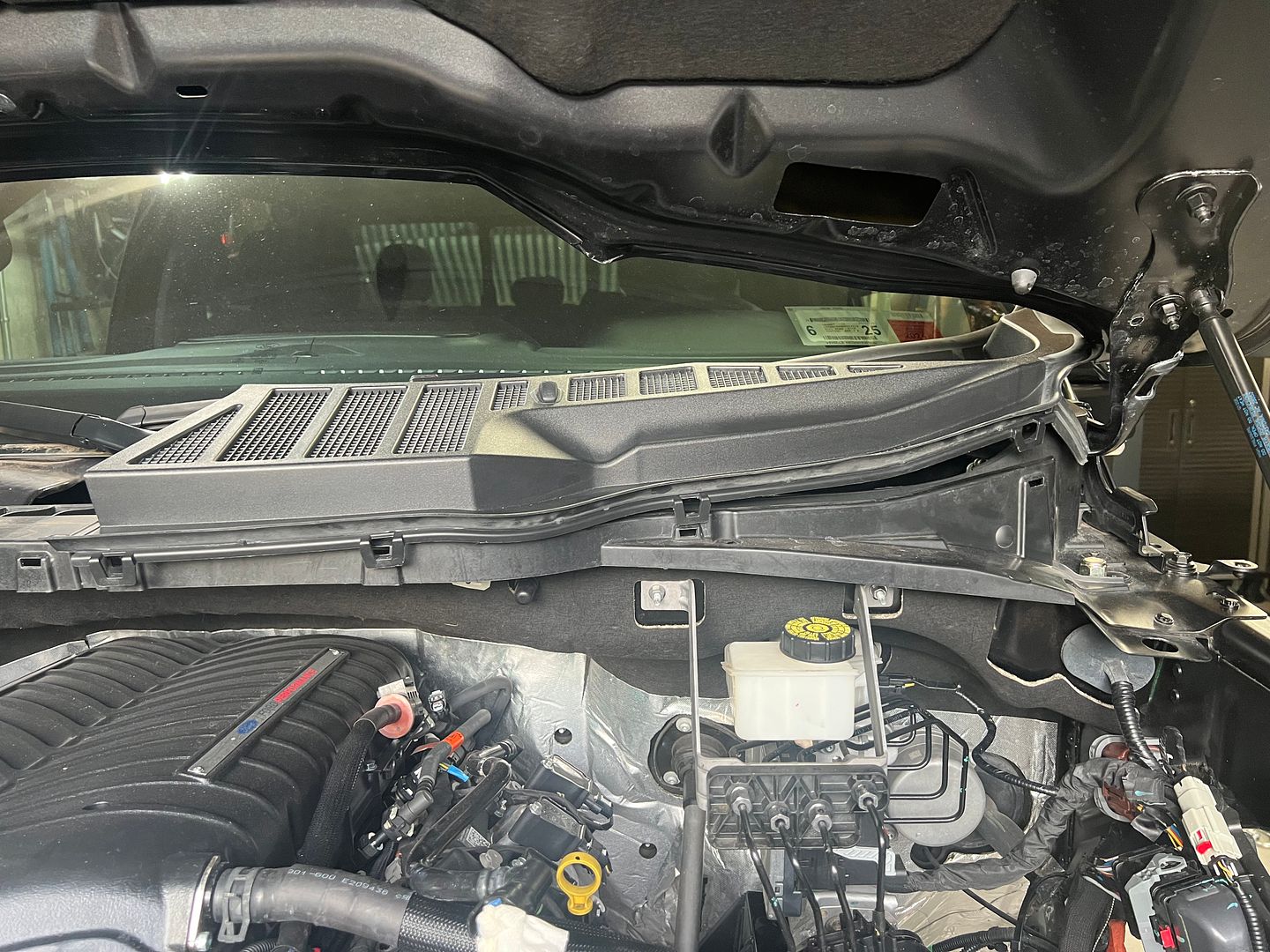
One interesting thing about working on a 2021 F150. Since the truck is relatively new there is very little DIY that is going on. Not much has broken yet. As a result there is little information available on the internet regarding procedures that apply directly to the 2021 model .
Normally you would look at the hood or core support for information regarding what refrigerant is used in the truck. Well the hood is gone now, so that’s not an option.
The printed manuals in the truck are not especially useful. The various guides have little maintenance information.
The owners manual is available in digital format however via the touch screen in the truck. I guess thats OK as it’s searchable, however it’s not what I expected.
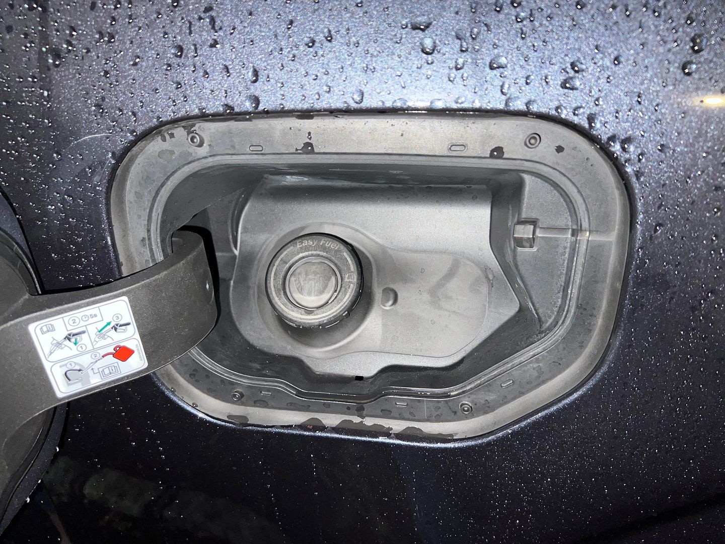
I assumed the truck used R134a refrigerant. Well that was wrong. Seems like Ford was switching over the trucks in 2021.
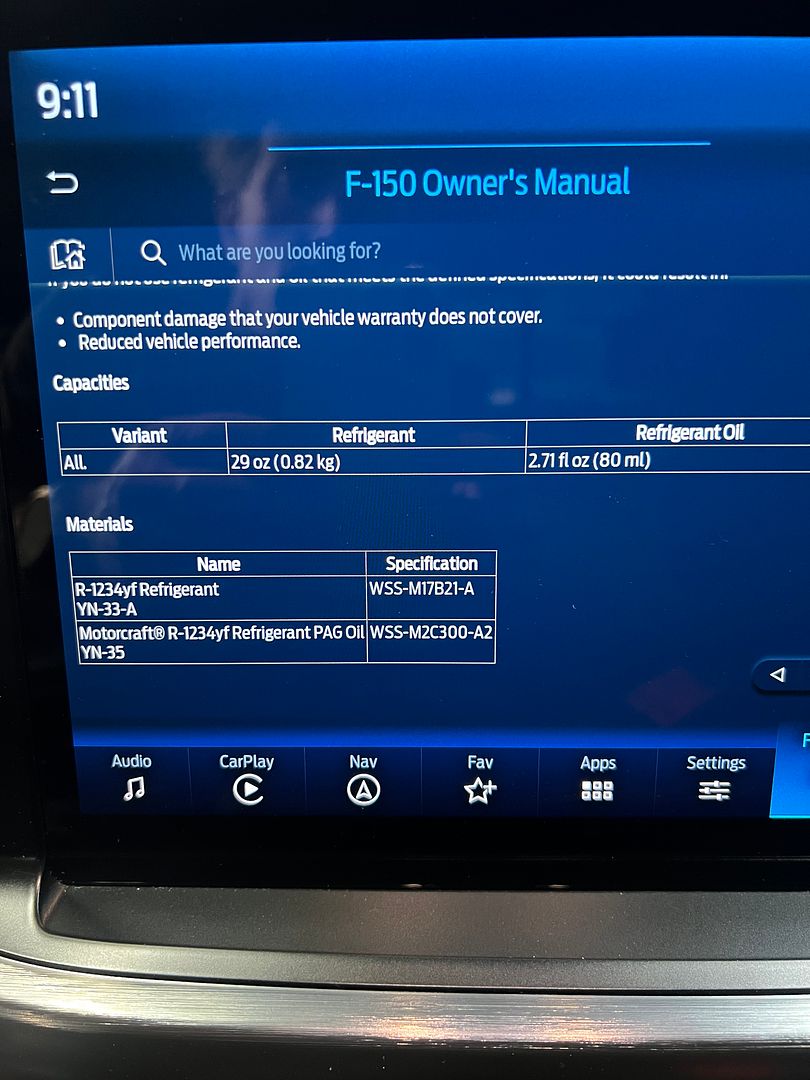
The 2021 F150 with a V8 uses y1234yf refrigerant. This requires different fittings than R134A.
XTF #2
build start date June 19 2023
GTM # 344
Build Start December 2010
First track day April 2013
-
Senior Member
John, As you obviously realize there is a hierarchy of materials and one begets another. When cosmetics are a fabricating priority at the expense of labor and speed:
Aluminum begets steel and SS.
Wood & plastic begets aluminum.
Leather over lead begets sheet metal.
On one occasion my dog's Nylabone helped me press a part to shape.
He got that tool back, no trophy.
jim
-
Post Thanks / Like - 0 Thanks, 2 Likes
-
Member
-
Post Thanks / Like - 0 Thanks, 2 Likes
-
Moderator
Have to laugh that a hose clamp was still there in final solution though
I totally get it, but *big grin*
James
FFR33 #997 (Gen1 chassis, Gen2 body), license plate DRIVE IT says it all!
build thread
My build: 350SBC, TKO600, hardtop, no fenders/hood, 32 grill, 3 link, sway bars, 355/30r19
Previous cars: GTD40, Cobra, tubeframe 55 Chevy, 66 Nova, 56 F100
-
Post Thanks / Like - 0 Thanks, 2 Likes
-
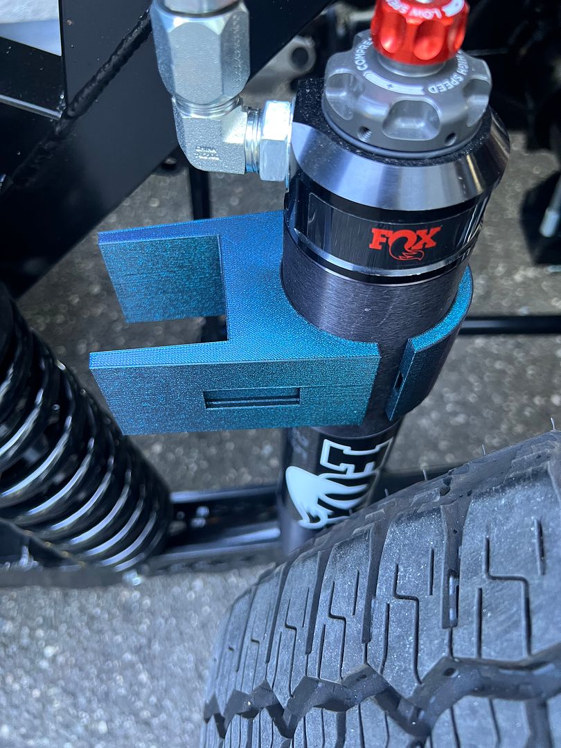
You could lose the hose clamp by making the clamp go all the way around the square tube and bolt together. You could use heat inserts to make the clamp threaded, or you could make flanges so a nut and bolt could go through. You can also embed nuts in your 3D print by having it pause after it has printed a hole for them to drop in, and resuming after you have added the nut.
-
Post Thanks / Like - 0 Thanks, 1 Likes
-
Member
Originally Posted by
RoadRacer
Have to laugh that a hose clamp was still there in final solution though
I totally get it, but *big grin*
I know. Its sad .
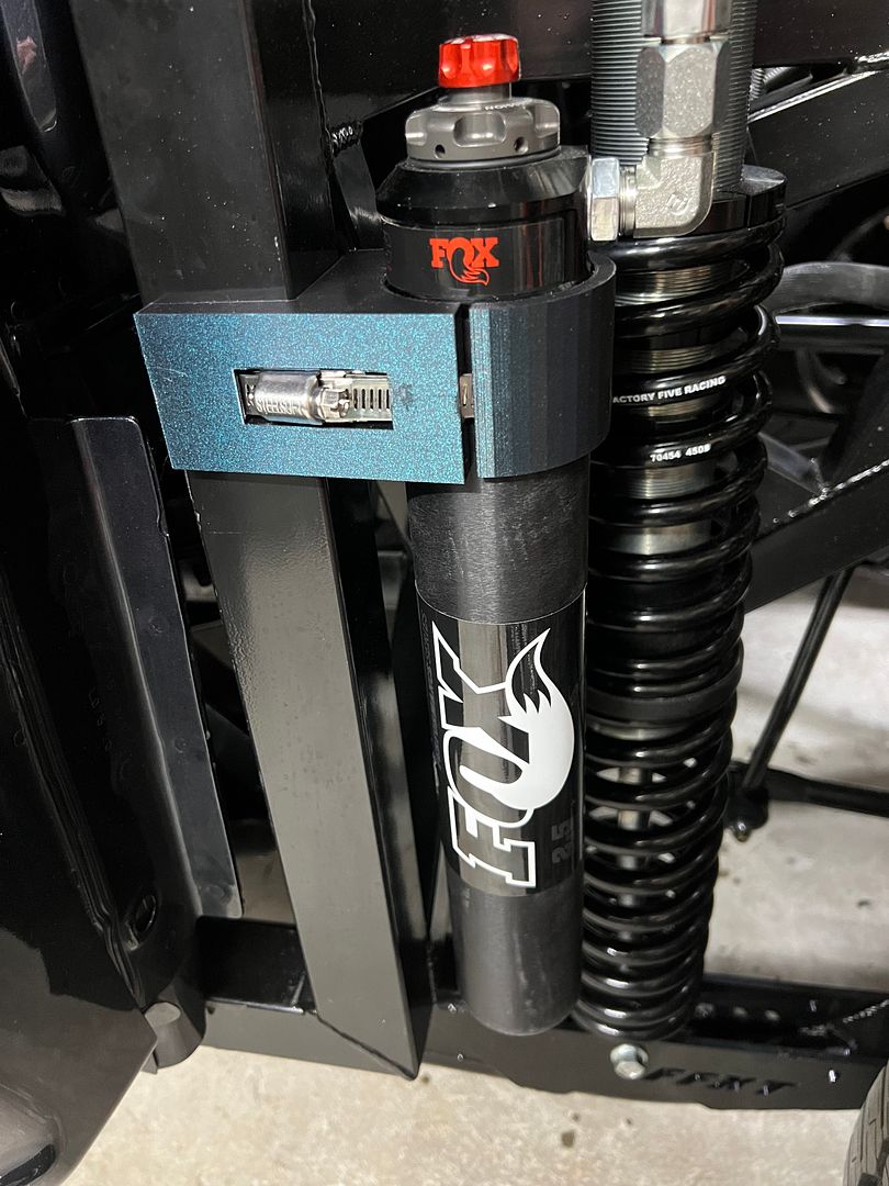
There is a reason that everyone just uses hose clamps.
Its a good solution. Simple and fail safe.
Any solution made of billet aluminum you are at risk of warping the housing of the remote reservoir. Easy to put lots of compression with a bolt. Hose clamps are not easy to over tighten.
Fox ships hose clamps and rubber saddles to mount the remote reservoir with the shock!
XTF #2
build start date June 19 2023
GTM # 344
Build Start December 2010
First track day April 2013
-
Member
Originally Posted by
Ajzride
You could lose the hose clamp by making the clamp go all the way around the square tube and bolt together. You could use heat inserts to make the clamp threaded, or you could make flanges so a nut and bolt could go through. You can also embed nuts in your 3D print by having it pause after it has printed a hole for them to drop in, and resuming after you have added the nut.
Yep good idea Ajzride. I like the stop the print and add the nuts solution.
Im going to add a cover to keep dirt out and hide the fact that I just used a hose clamp from RoadRacer.
XTF #2
build start date June 19 2023
GTM # 344
Build Start December 2010
First track day April 2013
-
If you do decide to enclose nuts in a print, buy a pack of square nuts. Easier to design in CAD and also allows you to insert the nut in any orientation. Regular hexagonal nuts can only be inserted horizontal.
-
Post Thanks / Like - 0 Thanks, 1 Likes
-
Senior Member
It is unlikely that any DIY replica will be held accountable to the SAE. The SAE requires auto assembly and maintenance with grade 5 or higher fasteners, to keep cars and drivers safe. SAE is like the FAA of road vehicles.
jim
-
Post Thanks / Like - 1 Thanks, 0 Likes


 Thanks:
  Likes:


 Reply With Quote


_IMG_0719.png?width=1920&height=1080&fit=bounds)