BUDFIVEs Roadster build in Central Texas-Getting Started on Wiring and Dash
Well, now that my roadster kit is on the rack at Factory Five, I want to start a build thread. I ordered my kit after attending build school in August. Stewart is set to pick up on 11/21 and deliver to central Texas about 11/27-29. Well have to trailer the kit the last half mile from the pavement up to the ranch shop.
While waiting since August Ive kept busy building the small block Ford roller 347, going for a dyno session(cool!), bolting up the clutch and transmission, bolting on all accessories and pulley kit, designing some of the sub systems, and purchasing lots of parts. The motor has been dyno tested and is ready for install. This forum has already been very helpful and Im glad to be part of itIm sure Ill consult with yall a bunch during the build, and hopefully contribute at some point.
Build Plan Summary:
Complete FFR Roadster Kit for IRS
Small block ford roller 347 internally balanced carbureted stroker (ranch build, more on this later)
Tremec TKX with close ratio
Power Steering
13 manual brakes
17 wheels
In-tank EFI style high pressure fuel pump with 3/8, 6AN feed and return lines, filters before and after pump, and bypass style regulator to 6.5 psi carburetor input. System upgradeable to EFI with regulator change.
Factory Five Kit order High Level (on the truck next week !):
Complete Kit for IRS Roadster, powder coated frame
Ford small block TKX config
Clutch quadrant
302 headers-polished
Bare 4 into 1 side exhaust
Power steering rack
Platinum Gauges
Wood steering wheel
Body cutouts
Trunk struts, visors, wind wings, mats, other miscellaneous
Halibrand replicas-17x10-1/2 Rear, 17x9 Front
Parts Acquired Separately (Already in the ranch shop)
Ford Roller 5.0 from 2000 Explorer
All parts for 347 build (separate post)
CVF 140A alternator, Saginaw power steering pump, serpentine pulley kit
800 psi power steering bypass reduction valve for Ford system
Tremec TKX 18084, close ratio with 0.81 5th (great debate)
Ford Performance D302B 23lb billet steel 0 balance flywheel
McCleod Super Street Pro Clutch kit
Tremec Bellhousing
SVF starter
Ford Performance Clutch cable and fork
Ford Performance 2015+ Mustang center section (M-4001-88355B)
Ford Performance IRS knuckles & Hubs (M-5970)
Summit racing EFI pump (Walpro rebrand)
Pro-M Racing fuel pump hanger with 3/8 output and return
Holley 12-881 4.5-9 psi bypass regulator
Summit 40 micron fuel filter (230101)
Powerstop 13 slotted/drilled Z26 2015+ Mustang GT rear brakes (KC6812-26)
Powerstop 13 slotted/drilled Z26 2004 Mustang Cobra style 2-piston front brakes(KC1304C-26)
Breeze Radiator shroud and Radiator hinges
Still to be Decided/Designed/Purchased:
Heater/Defroster system
Wiper system
Paint-probably Blue with White stripes (my two 30 something girls are helping)
Tires-Leaning Nitto 555 G2 315/35-17 Rear, 255/40-17 front
other, Im sure
This is a big project, maybe the biggest Ive taken on in my non-professional life. This is a BHAGa Big Hairy A** Goal. It has and will push me out of my comfort zone which is healthy. Glad to finally send this.
BUDFIVE
Last edited by BUDFIVE; 04-17-2024 at 10:46 PM.
Reason: Added powder coating, corrected Halibrand spelling
Folks, this post is the detail on the 347 I built for my Roadster build. I was serious about a cobra replica for a while so I specd this engine in June and scheduled build school for August. I built this with the help of Texas Engine Machine in Llano Texas and sbfbuilding.com (Jim aka Woody). I was always a Chevy guy so this was my first Ford build. I helped a friend build an LS earlier this year which was a great motor. But I wanted a small block Ford for my Roadster. This motor has a mix of new high tech(AFR heads, Bluetooth downloaded timing) and old school (carb) in an old small block Ford platform. I learned a lot.
It pulled 462 ft-lbs @4500, 432hp @5500 limited by a high rpm miss. I ran out of Dyno time to chase the miss, but I have subsequently found and fixed several possible causes. Anyway, the motor should be great in a light car with a TKX and 3.55 gears.
Specs/parts:
2000 explorer roller 5.0 HO block
ARP main studs and line hone
Eagle internal balance 4340 forged crank w/ 3.4 stroke
Scat 4340 forged 5.4 rods w/ 7/16 bolt upgrade
King HP main bearings
Clevite H rod bearings
Mahle Power Pak 4032 forged 4.030 pistons with 1/1/3 thin ring pack
Zero deck with Cometic .040 MLS for 10.7:1 compression and .040 quench
Bullet custom Hyd roller cam 228/236 dur @.050, .565/.575 lift, 109 LSA, installed at 106 intake centerline
Ford Racing m6500-302H high rev roller lifters
Ford Performance spider and dog bones
Rollmaster 10030 billet double roller timing set with dual Torrington bearings
Melling M68 std oil pump
1989 Mustang Oil pan with welded baffle on rear sump
AFR 185cc Renegade CNC heads with 7/16 rocker studs, 58 cc comb chamber
ARP 12-pt Head bolts
Scorpion Aluminum Roller Rocker Arms
Trick Flow/Trend .080 hardened pushrods
Edelbrock 7521 performer rpm air gap
Quick Fuel 650 Mechanical secondary
Progression Ignition Electronic Distributor, MSD Blaster 2 coil
Ford Performance 9mm Wires
I have a ton of pictures and love talking about it so feel free to ping me.
This was a fun motor to build and Im glad to have it ready so I can focus on the car build.
Congrats on your upcoming build and delivery. Sounds like a nice combination. A couple builds ago I did a 347 SBF also with Jim (Woody) and it was an an awesome engine. You're going to want to check that 1989 Mustang oil pan though to make sure it doesn't hang below the frame rails. With the kit supplied Energy Suspension motor mounts, oil pan depth needs to be 7.500 in. or less. I used a Moroso Street/Strip Oil Pan 20509. But there are lots of other choices.
Build 1: Mk3 Roadster #5125. Sold 11/08/2014. Build 2: Mk4 Roadster #7750. Sold 04/10/2017. Build Thread Build 3: Mk4 Roadster 20th Anniversary #8674. Sold 09/07/2020. Build Thread and Video. Build 4: Gen 3 Type 65 Coupe #59. Gen 3 Coyote. Legal 03/04/2020. Build Thread and Video Build 5: 35 Hot Rod Truck #138. LS3 and 4L65E auto. Rcvd 01/05/2021. Legal 04/20/2023. Build Thread. Sold 11/9/2023.
Edwardb, thanks-I double checked-its a Dorman 264-022 from Rockauto. Its a dual sump (2-drain plugs-hate it!) that has a shallow front sump and 7.5 max depth rear sump. The pickup is in the rear sump. We welded a baffle at the front of the rear sump to prevent all the oil from sloshing forward during braking. I thought the sides and rear of that sump are steep enough for cornering and acceleration.
Ill watch oil pressure closely in the car, it was fine on our Dyno session.
BUDFIVEIMG_0791.jpeg
Delivered. Stewart Transportation showed up this morning with my Roadster. Eric the driver took a ride with me in the Gator up the 1/2 mile dirt road to my shop-we decided to unload his truck at the pavement and use my trailer for for the last leg. So two pickup beds and cabs plus the trailer with body and frame and in an hour we headed up the hill. A friend and I unloaded all the boxes and pulled the trailer in the shop then started taking inventory. This evening some more friends showed up to unload the frame and then remove the body. So, a long day but a good day. Super excited to have the kit here.Jacks.jpgBuck.jpgTrailer.jpgTruckffr.jpgUnload.jpg
First 3 days after delivery:
-Added shelf to body buck to store doors, trunk and hood.
-Removed door and trunk hinges and Removed all aluminum panels from frame. Marked frame locations for drilling on those I was sure of position.
-Inventoried all boxes. Most boxes were checked fully, some checked at component level and bags of parts, not every fastener, connector, fitting etc. Not sure how obsessive to be on this? So far only missing extra brake fluid reservoir I added in my order. I still need to inventory the big fastener box this weekend.
-organized boxes on shop shelves, labeled and indexed
-procured nice screw machine length Hertel #30 and #11 bits for rivet drillingrigid and sharp
-recieved Milwaukee M12 rivet gun-very cool
-marked and drilled F-panels. Ready for priming and painting wheel well side.
I plan to use self etching primer and paint or undercoating spray on exposed underside and wheel well aluminum. Any guidance?
I like the aluminum look, especially in the engine compartment and plan to just clean and treat all others with Sharkhide. Other ideas?Bare.jpgBare2.jpgBodyoff.jpgBare.jpgBare2.jpgBodyoff.jpg
I think you made the right choice going with the close ratio TKX. I've driven roadsters with both the TKO500 and 600, the latter being a close ratio with .82 OD. Definitely prefer the close ratio and shorter OD. It's much more sporty haha. My car has the wide ratio TKO500 with .68 OD and 5th gear is strictly for 65+ mph highway cruising. I'm not a fan of it and have thought about swapping it to a TKX like yours.
Any reason why you chose the Mustang dual sump oil pan? I'm running a Canton road race front sump pan on my 302 and it works great. Also, what are your plans with the bare side exhaust? Ceramic coating?
Rmoore45
Good question. It seems funny looking back on the oil pan now but when I looked at the stock and Dorman 5.0 and 302 pans with the 7.5” max depth there were very few choices. I looked at a few aftermarket pans and their pick-ups and just didn’t find anything I liked under $500. In hindsight I wish I had posted the forum. So I decided to spend $50 and weld in baffles in the shop. I was going to run a standard volume and pressure oil pump so I thought the mustang pan capacity would be ok. On the Dyno, it held a steady 62psi with 10w40 during all pulls so we didn’t suck the pan dry, holding still If it is a problem in the car, I’ll learn my lesson and spend some more money.
Last edited by BUDFIVE; 12-11-2023 at 11:43 PM.
BUDFIVE
Complete kit order 8/28/2023
347 Ford Dyno 10/12/2023
Kit Delivery 11/28/2023
Also, I missed the 2nd question “plans with the bare side exhaust”…
I have a friend who’s pretty good with Ceracoat (and powder coat for hinges,etc).
I’d like to match the ceracoat side exhaust to the center of the Halibrand wheels. We looked at the colors turbine coat, titanium, and Mag silver. Turbine coat was closest but the wheel centers have a slight dark grayish blue to them. So we may try some mixing with a color like blue titanium and turbine coat, but from the same ceracoat series. We like the c-series with 1800 deg temp.
Last edited by BUDFIVE; 12-03-2023 at 07:11 PM.
BUDFIVE
Complete kit order 8/28/2023
347 Ford Dyno 10/12/2023
Kit Delivery 11/28/2023
WEEK 2 UPDATE
F-Panels
Painted wheel well side with Satin Black VHT Roll Bar and Chassis paint. On test strips the paint performed better without self etching primer.
Treated inside with Sharkhide.
Installed black rivets with my Milwaukee rivet gunthe bomb!
Happy with resultF-black.jpgF-shark.jpg
Front Suspension
Installed lower control arms
Assembled 2 piece spindles
Mocked up upper control arms and decided minimum length of the rear leg of triangle barely hit the target for power steering-8.5 on Jeff Kleiners diagram below. If you look closely in the pic you can see the coupler on the rear leg is shortened. So, I had a machinist friend turn the couplers down 3/16 on each end with a lathe. I pick those up Tuesday. IMG_0830.jpg
Center Section/Differential
Enlarged front mounting ear holes to 5/8. Used 5/8 tapered bridge bit bought on Amazon-worked great.
Installed driveshaft adapter to pinion flange and torqued 10mm socket heads.
With a friend helping, Used a transmission jack and lifted with front pitched up, then rocked front down, slid back into position as described in the build manual.
Bolted, torqued without drama Cendiff.jpgDiffpinion.jpg
Rear Suspension
My machinist friend volunteered to cut the IRS spindle/knuckles
we mocked the upper control arm connection to the spindle to see actual interference, scribed interference line radius.
Used a mill to cut the spindle ear and enlarge the remaining hole to 5/8will post picture in next update after I pick these up Tuesday
Unfortunately, the IRS fastener pack (17157) is missing the 8 (14925) M16-2.0x110mm grade 10.9 flange bolts to mount all four IRS control arms to the frame. The pack had all the flange nuts, but not these bolts. So, dead in the water on rear suspension-I will contact FFR Monday morning and see if they have them
Steering Rack
Replaced the bushings
Installed and torqued mounting bolts per manual
Screwed tie rod ends on until recommended starting ball joint stud separation (53-1/16) was achieved. Counted equal # turns on each side.
checked and theres less than 1 more I can reduce the span before the tie rod ends bottom on the inner tie rod threaded ends. Hopefully thats enough to hit the toe-in target. If not Ill have to cut the inner tie rods. Strg .jpgStr2.jpg
POL
-Have slowly compiled a list of a few missing items in addition to the POL from kit delivery. I was going to wait a bit but the missing control arm bolts have upped the priority
Good Week
It was a good and productive week. I continue to get help from wrenching friends, including one who is quite a machinist. I had a snag that caused one of those just walk away Buddy moments-its not important what it was but the fact that I thought of a sage forum post I read reminding me that this is fun and its ok to walk away. Im having a blast.
BUDFIVE
Complete kit order 8/28/2023
347 Ford Dyno 10/12/2023
Kit Delivery 11/28/2023
Front Suspension—builds on last weeks update)
—Received my UCA rear leg couplers back from my machinist friend
—Turned couplers down 3/16” on each end of coupler and 1/8” down on one threaded rod in a Lathe
—Result is good adjustment range around rough starting length (8.5”)
—Assembled remainder of front suspension-LCA, UCA, spindle, hub, coil-overs. IMG_4603.jpeg
Front brakes
—Installed 2004 Mustang Cobra/Mach1 style 2-piston 13” Powerstop brakes with Z26 pads
—Checked clearance with 17x9” front wheels, seems fine IMG_4619.jpegIMG_4630.jpegIMG_4611.jpeg
Rear suspension—builds on last weeks update
—Received my rear spindle/knuckles back from machinist friend
—Used a mill to remove required ear-left as much material on the spindle as we could, cutting on an arc with rod end jam nut 3 or 4 threads from shortest adjustment.
—So far adequate clearance through range of suspension travel and range of camber adjustment (UCA length) and toe arm adjustment.
—Assembled remainder of rear suspension-LCA, UCA, Toe arm, CV axle, Hub,Spindle, Coil overs IMG_4622.jpeg
Rear brakes
—Installed 2015+ Mustang Gt Powerstop 13” rear brakes with Z26 pads
—Checked clearance with 17x10.5” rear wheels-0.210” (2x0.105”) thick washers required to clear caliper. Will 1/4” spacers provide adequate clearance? Will 1/4” spacer result in a desirable 315/35-17 tire position? Picture is with .210” spacer. Edit:since this post I’ve been advised on the forum to grind a small amount from the calipers and repaint, rather than use wheel spacers. IMG_4625.jpegIMG_4629.jpeg
Overall a good week. If I mounted tires, I could roll the frame with front and rear suspension around the shop (Edited out incorrect use of phrase rolling chassis). Waiting another couple months on tires.
I’ll be off visiting relatives for a week so won’t have an update, but I will be on the forum for sure—learning a lot from y’all.
Last edited by BUDFIVE; 01-14-2024 at 12:10 AM.
BUDFIVE
Complete kit order 8/28/2023
347 Ford Dyno 10/12/2023
Kit Delivery 11/28/2023
On the road visiting relatives in Milwaukee this week. While away from my shop, I’ve been researching brake lines and buying some
Tools. I’m finding eBay to be a good source for used and new-old stock tools as long as I buy from a highly rated seller. This week I bought a Williams spanner wrench for the coil-over adjustment and a Ridgid 3/16 lever style tubing bender for bending brake lines.
I’m having fun with my build and have settled into a methodology before each section:
-Read manual
-Read build school notes
-watch FFR Build video on YouTube series
-Search forum for new ideas or clarity.
-set out as many parts and tools as possible
-write critical notes, key instruction page #s, draw pictures, and torque values on my marker board—especially helpful when working with helpers.
-Execute
Happy New Year-Back in Texas, spending the weekend working on the car.
A bit of progress on the Roadster this week-
Procured More Tools and Parts
—Happy with the tubing bender and spanner wrench which arrived from EBay
—2 ea 25’ spools of Marine Grade 316L stainless 3/16, .028 wall, seamless, soft annealed AGS/Brakequip for brakes, from Zoro
—3/16 and 3/8 tubing straighteners
Fitted, Drilled, Mounted more Aluminum panels
—Firewall(temporary, heater cutout required?)
—Pedal Box front wall IMG_4671.jpg
Installed Steering Shaft
—used carriage bolts instead of button head for bearing at front of pedal box—more positive alignment of bearing shell halves as bearing was tightened-bearing holes had square holes anyway
—cut 3/8” off lower DD shaft to reduce shaft depth in ujoints which were binding
—tested steering function—smooth left and right, no binding or notchiness IMG_4670.jpgIMG_4668.jpg
Assembled and Installed Fuel Tank
—Summit Racing (Walbro) 255 lph pump in tank
—Pro-M Hanger with 3/8 feed and return
—FFR tank vent
—FFR Fuel level sending Unit IMG_4666.jpgIMG_4667.jpg
Definitely looking more and more like a car.
Next weeks (or 2) plan
— I need to decide on heater/defroster design, cut and permanently install firewall.
—Procure 3AN stainless fittings for brakes and 6AN aluminum fittings for fuel
—Run 3/8,6AN fuel lines
—Run 3/16, 3AN brake lines
Glad to be back in Texas. Happy Wrenching
Last edited by BUDFIVE; 12-31-2023 at 10:42 PM.
BUDFIVE
Complete kit order 8/28/2023
347 Ford Dyno 10/12/2023
Kit Delivery 11/28/2023
Work this week on brake and fuel line fittings and brackets.
My strategy is as follows:
Brakes-
316L stainless 3/16, .028 wall, seamless, annealed line
Terminate lines with 37 degree flare and Earls SS 3AN Female Tube nuts and tube sleeves
Connections and fan out with Earls 3 AN SS male bulkhead fittings (straight and 90) and male bulkhead T fittings
18” Breeze 3AN to Banjo braided lines to calipers
Brackets are 12 ga steel riveted to frame
Fuel-
316 stainless 3/8 .035 wall, seamless, annealed line
Terminate lines with 37 degree flare and Earls aluminum 6AN Female Tube nuts and tube sleeves
Connections with Earls 6 AN aluminum male bulkhead fittings
6AN female to female soft lines from fuel pump hanger to filter and right rear bulkhead fitting.
Blue fittings for fuel feed line, black lines for return
Brackets are 12 ga steel riveted to frame
Received all the fittings and bought 12 gauge scrap steel at the metal yard. I layed out the lines
with 3/16 and 3/8” rope-this seemed over board but it really helped visualize. I cut mock up brackets from
cardboard then cut the 12 gauge steel with a plasma cutter, drilled and painted with satin black Rustoleum.
I have a few questions I posted in a separate thread on brake line routing (MC down to 4” tube for rear line, right rear bracket).
I plan to bend and flare the lines this week. When finished I’ll post some pics. Running these lines is all new to me. The forum has been very helpful with a lot of example threads.
Last edited by BUDFIVE; 01-08-2024 at 08:25 PM.
BUDFIVE
Complete kit order 8/28/2023
347 Ford Dyno 10/12/2023
Kit Delivery 11/28/2023
Good luck with the complex stainless brake bends! If youre not too far into it Id switch to Ni-Copp, much easier to work with in all facets.
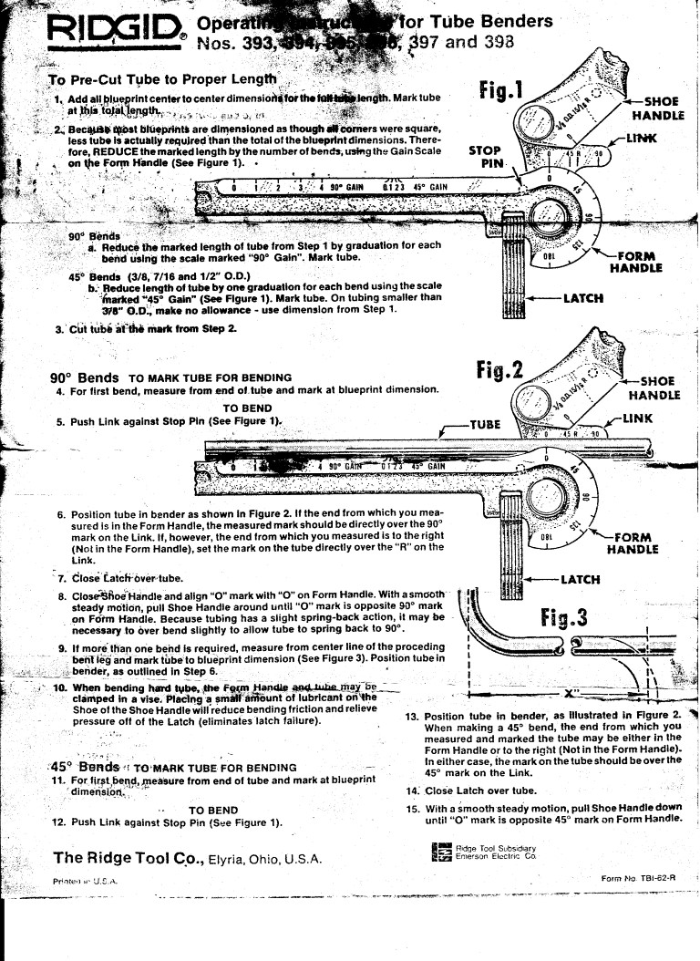
Stick with the stainless lines, you bought the good Ridgid bender so making complex bends that fall where you want is easy. Even I can do it. Did your bender come with the instructions? Feel free to reach out if you have any questions.
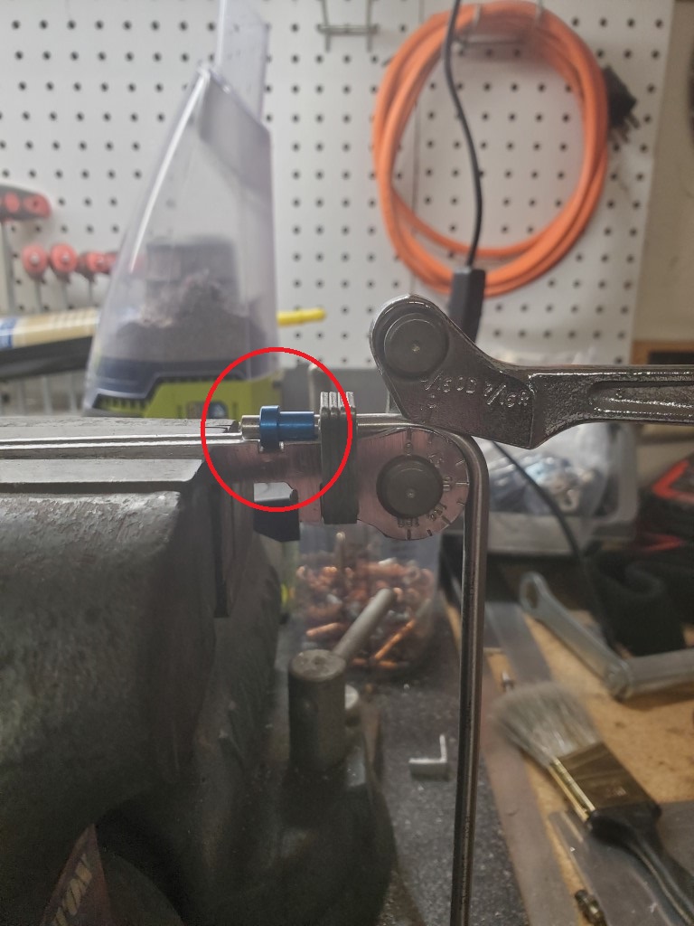
I milled a little slot in my 3/16" bender so I could make the bend closer to the end.
Fuel-
316 stainless 3/8 .035 wall, seamless, annealed line
Terminate lines with 37 degree flare and Earls aluminum 6AN Female Tube nuts and tube sleeves
Connections with Earls 6 AN aluminum male bulkhead fittings
6AN female to female soft lines from fuel pump hanger to filter and right rear bulkhead fitting.
Blue fittings for fuel feed line, black lines for return
Brackets are 12 ga steel riveted to frame
I used these compression fitting adapters for the fuel lines. They're fine for the relatively low pressure of the fuel system and very easy to use.
Thanks Mike, those might be handy where I turn up from the 4” tube at the front of the passenger footbox if I don’t have room for bulkhead fittings. And thanks, I also found the Ridgid instructions. My friend has the Ridgid 3/8 version bender for the fuel lines.
Last edited by BUDFIVE; 01-09-2024 at 11:23 PM.
BUDFIVE
Complete kit order 8/28/2023
347 Ford Dyno 10/12/2023
Kit Delivery 11/28/2023
Saw on the forum that some folks have fuel odor in their garages. With a carbureted, non-PCM build, I dont have OBDII features such as Evap/Purge for the fuel vapors. I couldnt find a cheap, compact canister so I made a fuel vapor canister from 1 PVC tubing, PVC end caps, 1/4 MIP to 1/4 hose barbs, scotch pad wad stuffing, and activated charcoal gravel. This is serviceable if the charcoal gets saturated. Connected to fuel hose from vent on top of tank. Well see if it works. Total cost $15. IMG_4714.jpgIMG_4715.jpgIMG_4711.jpgIMG_4716.jpg
Practiced bending 3/16 brake line with Ridgid lever bender. I was waiting for my friend who has experience bending and flaring stainless lines. I learned enough to be dangerous. IMG_4712.jpg
Im off to Louisiana tomorrow on a hunting trip. Hopefully, the rest of my brake line and fuel line parts arrive. Plan to bend fuel and brake lines later next week (I think I said that last week Stay warm yall.
BUDFIVE
Complete kit order 8/28/2023
347 Ford Dyno 10/12/2023
Kit Delivery 11/28/2023
Still cold here in Texas but I fit in some shop time and bent my stainless fuel lines. 3/8, .035 wall stainless is pretty tough to work with but I’m happy with them so far, including my frame mount for the bulkhead fittings near the tank. Yes, I know the black tube nut has a blue tube sleeve in it-Summit was out of the black tube sleeves-I only had 1 so I used it at the front where it’ll be visible I may fab some new frame mounts for the front of the lines at the 3/4” diagonal-for now I have couplers which would also be fine for transition to soft lines to the regulator. I still need to clamp the lines to the frame but laying on the shop floor at 39 deg last night was not appealing. I’ll post more pics when finished. IMG_4742.jpgIMG_4741.jpgIMG_4743.jpg
I received the FFR heater/defroster I ordered. I disassembled the heater, separating the blower half from the plenum half, to check the fitment compared to the provided template. The only issue was the copper pipes (5/8”) were all the way against the template hole (1-1/4”) at the 10 o’clock position. This would leave no room for a grommet on that side of the pipe. I re-marked and cut a new template which I’ll use to cut the firewall. I didn’t want to try bending the copper tubes and risk cracking the solder joint at the heat exchanger-I think I read this on the forum. IMG_4738.jpeg
Also received two more items:
-Breeze gas pedal with Wilwood style foot pad—this is really nice
-Ron Francis wiring harness from my POL—I’m a retired electrical engineer but the harness looks a bit intimidating. LOL
Heading out of town for 3 weeks down under in New Zealand and Australia-it’s summer there. Hopefully when I’m back the weather will be more conducive to working. I’ll be on the forum and studying next steps on my build— I will miss the build but this is probably as good a time as any.
BUDFIVE
Complete kit order 8/28/2023
347 Ford Dyno 10/12/2023
Kit Delivery 11/28/2023
Ron Francis wiring harness from my POL—I’m a retired electrical engineer but the harness looks a bit intimidating.
I know, right!? I did undergrad in EE, and have 6 years working as an avionics tech on airplanes. Yet, laying this harness out is already giving me simultaneous heartburn and flashbacks.
MKIV Complete Kit # 207585
Ordered 8/19/2023. Completion date 11/11/23. Delivery date 11/27/23
Back in my shop after 3 weeks down under. Good to have progress to report:
Heater/Defroster
Cut out the firewall as marked and coated with Sharkhide.
Used small 8-32 hanger bolts (stud with wood screw on one end and machine screw on other end) instead of just the supplied screws. This made aligning the heater halves and firewall holes much easier. It will also make service easier if required. IMG_4842.jpgIMG_4843.jpgIMG_4844.jpg
Installed the heater on the firewall on the bench then installed the pre-drilled firewall.
Fuel Lines
Attached fuel lines to the frame starting with the rear bulkhead fitting+metal frame mount followed by padded frame clips moving forward. Will do the forward hard line to soft line transition with a coupler and the hard line secured with a frame clipmuch easier than trying to end a hard line with a fixed bulk head fitting. My first hard line installation has been a learning experience. IMG_4853.jpgIMG_4854.jpg
Passenger foot box
Built the passenger footbox per the manual. Nothing too challenging.
But, since this is my first panel to panel riveting, its the first Ive used the FFR short 1/8 rivets. As others have mentioned seeing, these rivets have heads that are not machined/formed as nice as the longer rivets and they wont lay flush when installed-they stick up. So I bought some 1/8 x 1/8 Stanley rivets at the hardware store and all is well. IMG_4851.jpg
EbrakeI want to decide on (and maybe install) an ebrake solution before installing the aluminum floorboard. I have 2015 Mustang GT 13 rear calipers and 2015 Mustang ebrake cables. The caliper end of the inner and outer cables fit as expected. The front outer cable seems like it will fit the frame attachment in the tunnel but the cables are longer than needed so I may need to shorten them. Also Im going to have to get the inner cables to attach to the bottom of the ebrake handle. Searching the forumso far Ive seen a Lokar connector and McMaster car pulleys. More investigation required. Also considering the Estopp electronic parking brake solution.
Its good to be back in the shop. Were expecting more warm weather this week so Im planning a few more days work.
BUDFIVE
Complete kit order 8/28/2023
347 Ford Dyno 10/12/2023
Kit Delivery 11/28/2023
Hey BudFive, Looks like your having fun and things are coming along really well. Regarding the e brake, if your staying with the FF cable method I'd suggest you have a close look at EdwardB's fix for the e brake routing if you haven't already moved on from there. His fix is only doable when the tunnel aluminium is not attached yet. The manual has the cables running under the 4" tube, it's not great but it works until you install a Driveshaft Safety hoop then the interference from the hoop pushes the cables over and its too much to leave as it is. IMHO.
I found this out after my interior was completed so I'm under the car developing a fix that will work. There are other posts and fixes on this, I'm sure you'll come up with a plan that works.
2022 MKIV BP347, SniperEFI, IRS. Delivered June 22, Engine install Jan 23, first start May 23.
Howdy yallA productive week on the build. Great weather so lots of time in my shop.
Brake Lines
Finally ran the brake hard lines. 3/16 316L stainless, Earls stainless 3AN fittings, 12 gauge steel frame mounts.
These were not quite as tough to work with as the fuel lines. My Rigid tubing bender worked great as did my friends
37 deg flare tool. I did have a good pile of practice pieces and scraps-good for humility I routed the rear brake line through a bulkhead fitting at the drivers foot box front-I plan to shield this
from header heat with an aluminum channel or similar. Im happy with how they turned outpictures below. IMG_4866.jpgIMG_4871.jpgIMG_4875.jpgIMG_4874.jpgIMG_4872.jpgIMG_4876.jpg
Soft Lines for fuel system tank to hardline
Purged the fuel hard lines with brake fluid and compressed air. Then installed soft lines from the fuel pump to
the fuel filter and hard lines at the rear. IMG_4878.jpg
Rear Wheel Clearance
Isolated interference between rear caliper and 17x10.5 Halibrand replica.
Ground it down with die grinder then repainted-removed only ~1/16.IMG_4870.jpeg IMG_4877.jpgIMG_4869.jpg
A good week in the shop. Next plans are:
-install Breeze brake soft lines at each corner, install reservoirs, bleed system.
-mount fuel pressure regulator (waiting on 90 deg fittings), measure and order soft lines to connect.
-install breeze accelerator pedal and decide cable vs linkage, order.
-build drivers foot box.
Last edited by BUDFIVE; 02-25-2024 at 09:00 PM.
BUDFIVE
Complete kit order 8/28/2023
347 Ford Dyno 10/12/2023
Kit Delivery 11/28/2023
Light week in the with travel to Florida. But managed two installs before heading to the airport
-Installed the Fuel Pressure Regulator on firewall. Bypass style carburetor pressure range. (Holley 12-887, 4.5-9psi). Steps down
EFI in tank pump pressure to carburetor pressures and returns bypass to tank.
Used 3/8 NPT to 6AN fittings with 6AN 90 degree swivel fittings on input and output. Measured 3 required soft line routes
Input, Bypass, Out to Carb. Ordered braided stainless with blue, black and red ends, respectively. IMG_4879.jpeg
-Installed Breeze front mount Battery Mount per instructions. Continue to be impressed with quality delivered by Mark Reynolds. IMG_4881.jpg
Should be back in the shop this Friday 3/8plans included
-install Breeze brake soft lines at each corner, install reservoirs, fill and bleed system.
-install breeze accelerator pedal. Lokar cable and bracket ordered.
-build drivers foot box.
BUDFIVE
Complete kit order 8/28/2023
347 Ford Dyno 10/12/2023
Kit Delivery 11/28/2023
It's been 3 weeks since my last update. After Florida trip, Lots of shop time resulting in lots of progress2 posts, split out second post on ebrake since I hit pic limit
Tires
Ready to check brake soft line clearance and do first alignment so I needed to get tires. I bought Nitto NT555G2
255/40-17 Fronts for my Halibrand 17x9
315-35-17 Rears for my Halibrand 17x10.5
Very cool! IMG_4924.jpgIMG_4926.jpgIMG_4923.jpg
Breeze accelerator pedal and Lokar cable installed- very happy with the fitment and position adjustment vs brake pedal and driver foot box inside wall. IMG_4917.jpg
Fuel Pump, 316L SS hard lines, Regulator, Earls 6AN aluminum fitting test. Made a carb replacement stub with fuel gauge and 1/8 NPT-6AN fitting. Installed on fuel pressure regulator output. Connected 12V deer feeder battery to in tank fuel pump module. After tightening a few fittings and adjusting the FPR to 6.5 psi, confirmed fuel pump, hard feed and return lines, AN fittings, bypass regulator, etc. The carburetor and fuel log were tested during my Dyno run. I consider the fuel system a go. IMG_4952.jpgIMG_0936.jpg
Drivers Footbox and Brake Reservoirs
Assembled drivers footbox. Not too much drama but like others on the forum I had to trim about 1/4-1/2 from the trailing, vertical edge of the inside wall.IMG_4978.jpg
Breeze Brake -3AN soft lines, Brake Fill, Bleed, and Leak Test
Filled the reservoirs with Motul 600 Dot 4. Started pressure bleeding the front brakes and had multiple leaks-all at the 316L hardline flare to Earls Stainless 3AN bulkhead fitting. After tightening, most sealed, but we took one apart and realigned the flare as we tightened to ensure alignment. All leaks were eventually stopped and the brakes bled. Pedal feel is great. In conclusion, the stainless lines require much more torque at the tube nut/sleeve, flare, bulkhead fitting junction than I expected. It is definitely more work to do stainless lines-some of you are saying I told you so. But, Im happy with them IMG_4975.jpg
Upcoming-second post on ebrake
BUDFIVE
Complete kit order 8/28/2023
347 Ford Dyno 10/12/2023
Kit Delivery 11/28/2023
Ebrake-2015 Mustang GT caliper and ebrake cables, FFR ebrake handle, hardware
Using the edwardb pulley solution which routes the brake cable above the 4 frame (rather than under it). Slight implementation highlights and differences:
1) 1 square tube is welded under the 1 frame tube to mount the pulleys-2 McMaster Car 3434T24. This allowed me to twist the block to tilt the pulleys more in the direction of cable travel and to achieve a lower position than drilling the pulley axle hole in the frame. Two holes were drilled in the block for pulley location flexibility before the weld.IMG_4970.jpgIMG_4972.jpg
2) Factory Five ebrake handle extended at cable attach point for lowered position (clears bottom of ebrake frame bracket) and more travel.IMG_4976.jpgIMG_4977.jpg
3) Lokar WCA-8070 Cable connector block, heim joint. The connector block is has a full length 5/16-24 hole. I found a Heim joint male rod end with 5/16-24 threads-this combination yields a very compact adjustable connection for the cables to the ebrake handle.IMG_4983.jpg
4) Removed inner cables from cable sheaths, cut sheaths to length, relocated forward cable end to shortened cable sheath (epoxied). Enlarged frame cable sheath mount holes to 9/16.
5) After mock up, the parts have been painted and are drying. Ill post more pictures after final install in a couple days.
Overall, Im happy with the progress and especially glad to have tested both the fuel system and brake system. Almost finished with ebrake.
Upcoming
Finish install and post pics of ebrake solution
Lower to ride height, Align with Fastrax caster/camber tool
More cockpit aluminum
BUDFIVE
Complete kit order 8/28/2023
347 Ford Dyno 10/12/2023
Kit Delivery 11/28/2023
Finished E-brake install and adjustment—yeah!!
Since last update I moved the heim joint cable end to a mid point on the handle extension which yielded adequate clearance from the handle mount carriage bolt and more leverage than the furthest end of extension. It was a tradeoff-clearance & cable travel(better further from handle fulcrum) vs leverage (better close to fulcrum). So the middle worked best. I also moved the pulleys back to the rear, lower hole location on my welded block, providing better cable retention in the pulleys with slack cables (brake relaxed). The brake works great with 4 or 5 clicks to full tight.IMG_5010.jpeg
Last edited by BUDFIVE; 03-31-2024 at 10:19 PM.
BUDFIVE
Complete kit order 8/28/2023
347 Ford Dyno 10/12/2023
Kit Delivery 11/28/2023
-Adjusted TKX Shifter position and welded new cross brace on frame tunnel to make room.
-The TKX has an easy modification to the shifter-remove 6 bolts, rotate shifter plate, re-install 6 bolts. This moves the shifter location about 3-1/2” forward in 20 minutes. IMG_5035.jpgIMG_5036.jpgIMG_5037.jpgIMG_5038.jpg
-Mocked-up the transmission position and the above shift position change would interfere with a cross piece on top of the transmission tunnel. I verified this by reviewing build school pictures (also a SBF, TKX combo) which showed that the forward shift position would interfere. So I cut a new cross piece and welded it in place then cut the old one out. IMG_5039.jpgIMG_5040.jpg
-Finished as much of the cockpit aluminum as I want to do before making progress with the wiring harness. IMG_5044.jpgIMG_5041.jpg
Next steps-
-First pass alignment
-Start work on wiring harness and dash/gauges
Last edited by BUDFIVE; 04-05-2024 at 09:54 PM.
BUDFIVE
Complete kit order 8/28/2023
347 Ford Dyno 10/12/2023
Kit Delivery 11/28/2023
A friend of mine who just put a harness in his restomod build came and helped in my shop for a daywhat a help!
We got the main harness and sub harnesses all in place. As much as I didnt want to, I mounted the fuse box in the recommended location, under the master cylinder outputs. Ill make a chute out of coated cardboard to divert any drips past the fuse box. IMG_5062.jpgIMG_5061.jpgIMG_5063.jpg
Note in this pic that the front harness goes through the DS foot box aluminum slot which Ive made a small cover for with a through hole.
From this through-hole the front harness can go up to the top frame rail or go forward on the middle 3/4 with the front brake line (kind of prefer this). I havent decided. Input? IMG_5064.jpeg
At the end of the day, we tested the following,
-Continuity from battery node through start node on ignition switch to Solenoid wire in engine bay with clutch depressed(CSS clutch safety switch, ign switch)
-Continuity from battery node on ignition switch to brake light wires in trunk when brake depressed (brake switch)
-Fuel pump kicks on with ign On, inertia switch reset, 12V deer feeder battery + on battery wire in engine compartment and - to frame
I know this is just a start, but I believe a good start. Im sure there will be opportunity for my continued humility
Next steps:
-Run 2 wires from NSS (neutral safety switch) in tunnel to DS footbox, join with 2 wires on CSS. This will put NSS in parallel to CSS so either clutch depressed or TKX in neutral will allow start. Picking up Ron Francis NSS pigtail at Summit this week.
-Splice (solder) 5:4 converter into rear harness to combine Brake and Turn functionality into rear LEDs.
-Heat shrink terminate all unused wires in harness(EFI, etc) Tuck away for future as needed use
-Mount headlight dimmer foot switch in DS foot box. Route 3 wires from foot switch pigtail up into dash harness. These 3 wires are in a separate group in the dash harness, cool. More on dash below.
As Ive seen many do before, my dash is on the ranch house kitchen table. My plan is as follows, not in any order:
-Platinum gauges (Speed, Tach, Volt, Water T, Oil P, Fuel) + Oil T. There is no Oil T gauge in the Platinum line. I am working with a Autometer 200764-35 which has a chrome bezel and orange needle vs Platinum gauges Black chrome bezel and black needle. Im experimenting with Black Smoke Anodized paint from Duplicolor. Test sprays on a chrome socket look promising. I cant help the orange needle-well see.
-FFR IGN switch
-Foot switch for high/low beam
-FFR headlight pull, dimmer
-i.e.427 turn signal, hazard, horn function
-4 position fan switch (off, lo, med, hi), replacing combo fan/mechanical pull vintage switch
-On/Off toggle for heater on/off. This powers US Solid Solenoid switch for heater water flow. This replaces mechanical choke cable style valve.
-LED green arrows for turn indication, blue with light symbol for high beam indication
-Marine dual-USB hi current charger port
-Havent decided on courtesy light
I ordered parts for above and took time out to finish and mail Taxes. I also fit in a couple days to pull the transfer case and install a slip yoke eliminator kit on my Jeep TJ to improve driveline vibrationdue to 4 of lift and a really short driveshaft at severe angles. The TJ is my last build with a 4.7L stroked 4.0 in-line six. Fun and something to work on when Im waiting on parts or need a distraction.
Still having a blast.
BUDFIVE
Complete kit order 8/28/2023
347 Ford Dyno 10/12/2023
Kit Delivery 11/28/2023


 Thanks:
  Likes:


 Reply With Quote


 If it is a problem in the car, I’ll learn my lesson and spend some more money.