Boig Motorsports

Visit our community sponsor

Thanks Thanks:  0
Likes Likes:  0
Results 1 to 17 of 17

Thread: Questions on '04 Corvette Donor Gas Tanks

  1. #1
    Member
    Join Date
    Feb 2011
    Posts
    58
    Post Thanks / Like

    Cool Questions on '04 Corvette Donor Gas Tanks

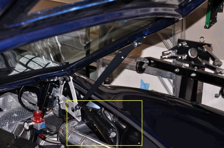
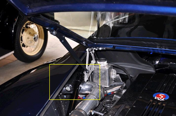
    Trying to wrap up a few things in preparation for go-carting soon. I'm using the '04 donor tanks.

    Questions:
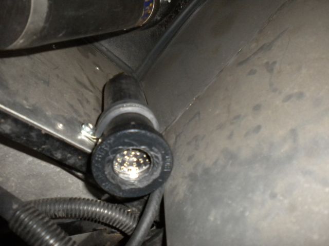
    1) What should be done with the ventilation lines coming out of each tank? I've seen some threads with them capped, others have created a ventilation system using hollowed out sprinkler heads, others use the Vette donor filters. I assume leaving them open is a serious hazard. What are the recommendations out there?

    2) Do both of the Fuel Level Senders need to be connected to the Fuel Gauge to create enough signal to give an accurate reading? With the crossover line being at the bottom of the tanks in the FF install, obviously the fuel level will be the same in both tanks, but I believe I saw in some thread that both senders are needed for adequate signal.

    3) I've looked at the Vette wiring diagram for the correct wiring of the Fuel Senders but if someone has a wiring diagram specifically for the GTM with SpeedHut gauge, I'd like to see it.

    Thanks for any help,

    EB

  2. #2
    Senior Member The Stig's Avatar
    Join Date
    Feb 2011
    Location
    Charlotte, NC
    Posts
    2,004
    Post Thanks / Like
    Hi Drea,

    I went with the aluminum tanks that Ron Richmond and Ted Harrison (Quick Racing Products) sell. I was also looking for a way to vent the tanks, and decided to try out the "Home made" charcoal filters that I read about. I thought it was a very good idea, and as easy to make. So I made one for each tank, and ran them inside each of the rear fenders. I have them temporarily "zip-tied" to the rear cage brace. When I disassemble the suspension to rebuild the control arms, I'll find a place (out of the way) to permanently mount them. The filters are highlighted in the pictures below.


    The Stig

    Some say, that I only know two facts about ducks, (both being wrong); and that if I could be bothered, I could solve the "da Vinci Code" in 47 seconds...
    All I know is that I'm called "The Stig".
    GTM #0081

  3. #3
    Member
    Join Date
    Feb 2011
    Posts
    58
    Post Thanks / Like
    I'm going to give this a try too. Seems like a simple solution. Thanks.

  4. #4
    Senior Member The Stig's Avatar
    Join Date
    Feb 2011
    Location
    Charlotte, NC
    Posts
    2,004
    Post Thanks / Like
    Drea,

    I cut/pasted this from my build thread. Glenn (Weendoggy) sent this to me in response to a request for charcoal filters that could be used on the GTM.

    ***************
    You can make an inexpensive charcoal filter yourself by using a 4" yard popup sprinkler, gutted, sink strainer and charcoal for an aquarium. A lot of us are doing that on our roadsters and they work quite well. You could probably hide it from your engine bay for a clean look too.

    Check this thread http://www.ffcars.com/forums/17-fact...al-filter.html and look at post #5. I made mine similar to this but did some extra things.
    1. Take the guts out, go to a pet store and buy a small box of charcoal (usually in pellet type), get some fine SS mesh screen from a hardware store in the sink stopper area and a small 1 1/2" sink strainer.
    2. After taking the guts out, check to make sure the sink strainer will fit (I did this in the store to make sure it would), open up the thread top to allow a little extra breathing room (I just used a knife)
    3. Cut the fine mesh screen (mine was from a SS strainer I cut from a store bought strainer) large enough to fit in the sprinkler body but not come out the threaded end, cut another one to fit just under the sink strainer to keep the charcoal from coming out.
    4. Put the small piece in the bottom, fill with charcoal, put the second fine mesh and sink strainer on followed by the screw top.
    5. Now all you need is a 1/2" NPT to hose size of your choice on the end of the sprinkler and you can install. I secured mine with a large loom insulated clamp.

    Picture of mine installed.


    Hope this helps.

    Mike
    The Stig

    Some say, that I only know two facts about ducks, (both being wrong); and that if I could be bothered, I could solve the "da Vinci Code" in 47 seconds...
    All I know is that I'm called "The Stig".
    GTM #0081

  5. #5
    Senior Member mikespms's Avatar
    Join Date
    Apr 2011
    Location
    North Miami,FL
    Posts
    145
    Post Thanks / Like
    Hi,
    Those tanks are equipped with a on-board refueling vapor recovery system that works with the EVAP canister and the evaporative emission control system. If you used a donor car it is easy to install the complete emission system which would make you 50 state legal and the only thing you have to change is the vent line to the filler neck, those are the two vent lines on top of the tanks connecting the tanks together and venting to the filler neck, just use a inline fuel filter and a hose to run the vent out
    Last edited by mikespms; 05-03-2012 at 10:20 AM.

  6. #6
    Member
    Join Date
    Feb 2011
    Posts
    58
    Post Thanks / Like
    Mikespms -

    I didn't use a complete donor, so I'd have to buy the EVAP cannister. That's no big deal, but as far as I can tell from looking at the stock Vette schematics that EVAP system has a solenoid that opens once the cannister gets full (pressure or volume?) and returns the contents to the tanks. My concern is that without the stock ECU there's no trigger for the solenoid to open and the EVAP cannister never gets vented. I like the idea of using this system, but clearly it needs to be fully operational or it could be more of a hazard. I think the simple sprinkler set-up might work fine unless someone out there has made the stock set up work.

    Can anyone pass on diagrams of how they hooked up their evap system?

    Thanks.

  7. #7
    Senior Member VD2021's Avatar
    Join Date
    Feb 2011
    Location
    Central, FL
    Posts
    958
    Post Thanks / Like
    Blog Entries
    2
    No fuel enters the canister only vapor. The evap canister motor moves and scrubs the fumes.

    You can add the donor canister without the use of the full evap system using it as Mike did with his sprinkle/charcoal setup. There are not valves so fumes/air can move through. Not only will this get rid of the fumes it should make fueling the tanks easier also.
    R/s
    Vidal
    CURRENT STATUS: Interior Rework and Bodywork.
    GenII GTM #331. Delivered (23/9/10)
    BUILD LOG AND WEBSITE:
    http://gtmbuild.weebly.com/ .

  8. #8
    Senior Member The Stig's Avatar
    Join Date
    Feb 2011
    Location
    Charlotte, NC
    Posts
    2,004
    Post Thanks / Like
    Quote Originally Posted by VD2021 View Post
    No fuel enters the canister only vapor. The evap canister motor moves and scrubs the fumes.

    You can add the donor canister without the use of the full evap system using it as Mike did with his sprinkle/charcoal setup. There are not valves so fumes/air can move through. Not only will this get rid of the fumes it should make fueling the tanks easier also.
    Exactly! I didn't have the Charcoal canister from the Donor. (Not really sure where that went)... I needed a way to scrub/filter the fumes, as well as provide an ability for the tanks to "breathe" when refueling. I can attest to the fact that the fumes that once filled my garage, are a thing of the past! So for now, this was a very nice solution.

    Thanks Vidal.
    The Stig

    Some say, that I only know two facts about ducks, (both being wrong); and that if I could be bothered, I could solve the "da Vinci Code" in 47 seconds...
    All I know is that I'm called "The Stig".
    GTM #0081

  9. #9
    Senior Member mikespms's Avatar
    Join Date
    Apr 2011
    Location
    North Miami,FL
    Posts
    145
    Post Thanks / Like
    Quote Originally Posted by dreabrown View Post
    Mikespms -

    I didn't use a complete donor, so I'd have to buy the EVAP cannister. That's no big deal, but as far as I can tell from looking at the stock Vette schematics that EVAP system has a solenoid that opens once the cannister gets full (pressure or volume?) and returns the contents to the tanks. My concern is that without the stock ECU there's no trigger for the solenoid to open and the EVAP cannister never gets vented. I like the idea of using this system, but clearly it needs to be fully operational or it could be more of a hazard. I think the simple sprinkler set-up might work fine unless someone out there has made the stock set up work.

    Can anyone pass on diagrams of how they hooked up their evap system?

    Thanks.
    If you are using a crate engine with a stand alone ECM I don't know if it will work you would need a schematic of your ECM connectors but if your are using a c5 corvette PCM you can make it work.
    In order to make it easy you would need to have the harness to the tanks and the complete engine harness . To complete the emission system the air injection system lowers the exhaust emission levels by forcing air into the exhaust stream these systems are controlled by the PCM . With the harness you use the plugs that connect to the tank components,EVAP and AIR system. Take the connectors with as much of the wire attached to them as you can, the wires are color coded and it makes it easier to trace and find their connections to the PCM . EVAP controls are EVAP purge solenoid,EVAP canister vent solenoid and fuel tank pressure(FTP) sensor they connect to the PCM. The AIR system is wired on the engine harness and it has three components the air pump relay(that is part of the underhood fuse block and is wired to the engine harness)the secondary air injection pump and the secondary air injection solenoid. With the service manual schematics is easy to trace and see where the wires and connector go and if you have acces to a donor car it needs to be the same model and year as your components.
    Last edited by mikespms; 05-04-2012 at 11:20 AM.

  10. #10
    Senior Member VD2021's Avatar
    Join Date
    Feb 2011
    Location
    Central, FL
    Posts
    958
    Post Thanks / Like
    Blog Entries
    2
    Quote Originally Posted by dreabrown View Post

    Can anyone pass on diagrams of how they hooked up their evap system?

    Thanks.
    Mike,

    Nice write-up Mike.

    D,

    Here's how I would do it if I were not using the entire evap system but wanted to use only the donor charcol canister.

    -Use 3/8" fuel injection line to connect the vent lines from the fuel tanks. The vent lines have green or blue circle on the diagram.
    -Use 3/8" fuel injection line to connect the vent (that was originally connected to the gas cap vent) to the fitting (circled with blue in the picture) on the canister.
    -Cap the larger canister connection (Circled with red in picture).
    -Leave the other open to vent the system. (there is a chance the two larger canister connections should be opposite of what I suggest, I don't have the service manual with me to verify)

    HTHs
    Attached Images Attached Images
    R/s
    Vidal
    CURRENT STATUS: Interior Rework and Bodywork.
    GenII GTM #331. Delivered (23/9/10)
    BUILD LOG AND WEBSITE:
    http://gtmbuild.weebly.com/ .

  11. #11
    Member
    Join Date
    Feb 2011
    Posts
    58
    Post Thanks / Like
    Bump

    Does anyone have wiring diagram for 04 tanks to Speedhut gauge? I've tried wiring each sender individually and manually moving it to get the gauge to move, but it doesn't budge. What am I missing?

    Several other PMs reveal others are having problems too

    Thanks

  12. #12
    Member
    Join Date
    Mar 2018
    Location
    Plano, TX
    Posts
    90
    Post Thanks / Like
    Quote Originally Posted by dreabrown View Post
    Bump

    Does anyone have wiring diagram for 04 tanks to Speedhut gauge? I've tried wiring each sender individually and manually moving it to get the gauge to move, but it doesn't budge. What am I missing?

    Several other PMs reveal others are having problems too

    Thanks
    Did you ever figure out how to wire the senders to the gauge? I'm imaging some sort of circuit adding the two voltages together. What'd you find out?
    Ryan
    GTM #511
    Build log: gtm.perkinsons.com

  13. #13
    Member
    Join Date
    Mar 2018
    Location
    Plano, TX
    Posts
    90
    Post Thanks / Like
    Quote Originally Posted by Perkster029 View Post
    Did you ever figure out how to wire the senders to the gauge? I'm imaging some sort of circuit adding the two voltages together. What'd you find out?
    Actually, I think I just figured it out. Our senders appear to have variable resistance, from 40 ohms [empty] to 250 ohms [full] (ish). Averaging the two resistances, and sending that to the gauge, should work. You could probably also take a shortcut and route only one sender's signal, if you assume the crossover tube being located pretty low keeps the two tanks about the same level.
    Ryan
    GTM #511
    Build log: gtm.perkinsons.com

  14. #14
    VRaptor SpeedWorks, LLC's Avatar
    Join Date
    Feb 2011
    Posts
    1,458
    Post Thanks / Like
    All of the newer fuel gauges are programmable......so you only need to use one sender from one tank.
    Shane Vacek
    VRaptor SpeedWorks, LLC
    www.vraptorspeedworks.com
    Turn-key GTM, SL-C & Ultima GTR Built to Your Specs!
    Offering a full line of GTM Upgrades and Custom Parts

  15. #15
    Senior Member beeman's Avatar
    Join Date
    Feb 2011
    Location
    Indiana
    Posts
    1,490
    Post Thanks / Like
    Do you need to vent the Corvette gas tanks in addition to venting for filling? I mean, do you need a constant vent? Or just while filling? I'm planning on venting back to the OEM vette filler neck which will be sealed when the gas cap is on.
    MK3.1 2004 Mach 1 donor. ABS, PS, TC.
    GTM #304 LPE 525hp LS3
    2000 C5 Lingenfelter LS1@489hp
    1999 Corvette FRC/Z06 track car

  16. #16
    VRaptor SpeedWorks, LLC's Avatar
    Join Date
    Feb 2011
    Posts
    1,458
    Post Thanks / Like
    Yes, you need to have a way for the tanks to pull in air as fuel is used out of the tank so the fuel pump isn't trying to suck the tanks down into a vacuum.
    Shane Vacek
    VRaptor SpeedWorks, LLC
    www.vraptorspeedworks.com
    Turn-key GTM, SL-C & Ultima GTR Built to Your Specs!
    Offering a full line of GTM Upgrades and Custom Parts

  17. #17
    Senior Member beeman's Avatar
    Join Date
    Feb 2011
    Location
    Indiana
    Posts
    1,490
    Post Thanks / Like
    Ah, makes sense. Thanks.
    MK3.1 2004 Mach 1 donor. ABS, PS, TC.
    GTM #304 LPE 525hp LS3
    2000 C5 Lingenfelter LS1@489hp
    1999 Corvette FRC/Z06 track car

Tags for this Thread

Posting Permissions

  • You may not post new threads
  • You may not post replies
  • You may not post attachments
  • You may not edit your posts
  •  

FFMetal

Visit our community sponsor