
Visit our community sponsor

Thanks:
2

Likes:
1
-
Senior Member

Wiring Update
Had this past week off from work. Ate too much and watched too much football. But was still able to get a lot of quality build time. Its amazing how the hours fly by. Looking back at the week, seems that I didnt get as much done as I hoped. But things just take a long time (for me anyway) and even though Im pretty comfortable with electrical wiring, Im going really slow taking a lot of notes and testing repeatedly to make sure everything works as expected.
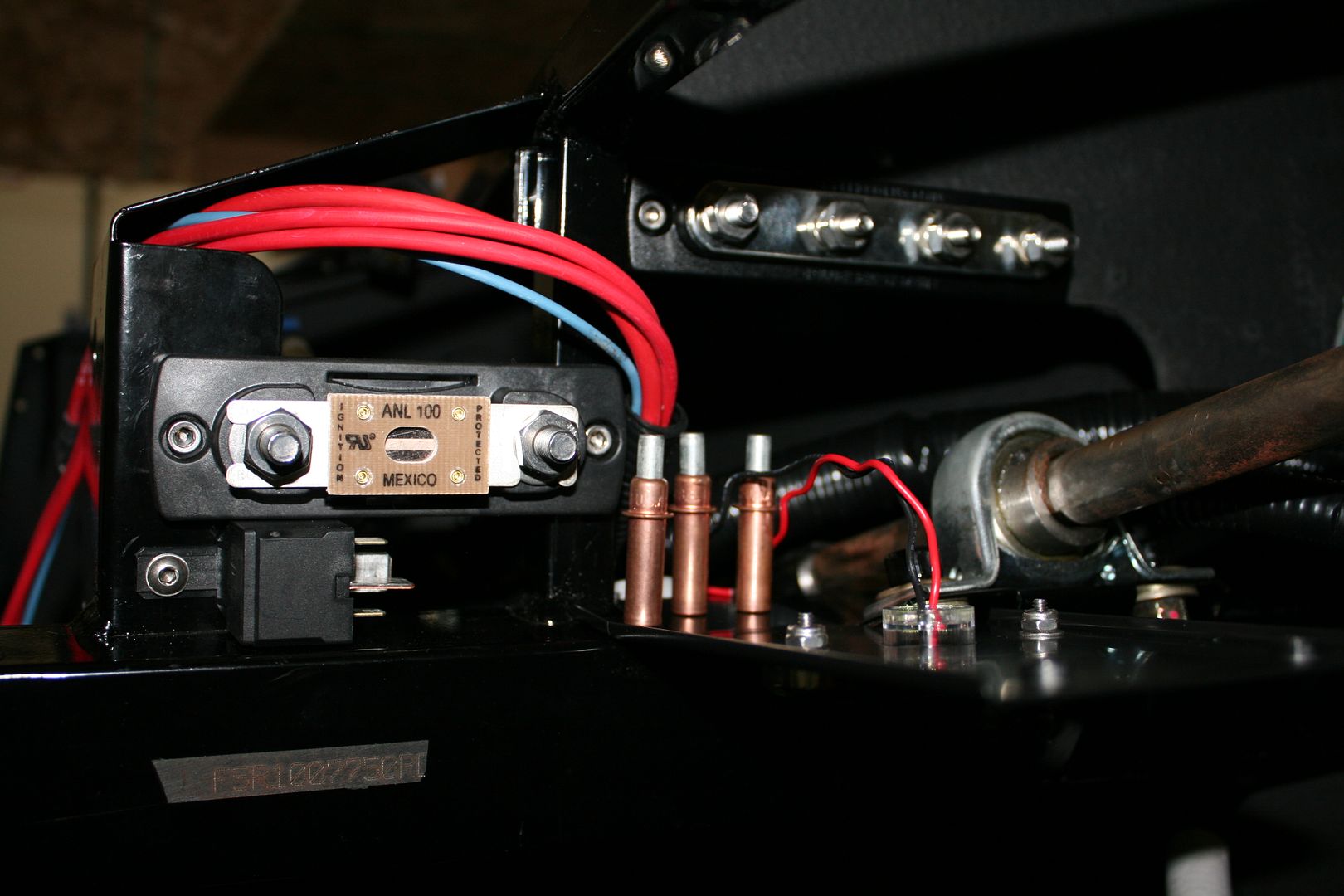
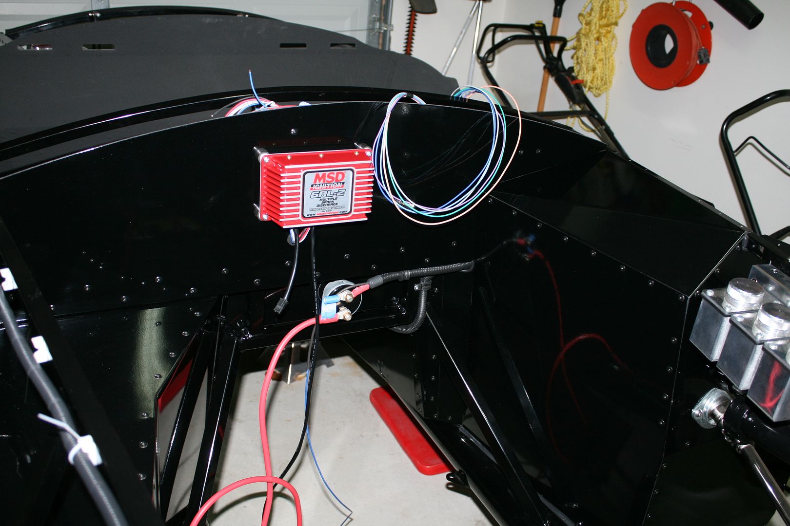
Im using a standard FFR supplied Ron Francis harness. In my last update I outlined several of the changes and additions Im making. I have a front mounted battery (Breeze) and a master cut-off switch centered under the dash. So power comes from the battery to the cut-off switch, and then back to the starter plus a branch to the fuse panel. I brought the main power into the dash area using a Blue Sea Systems bus bar. These parts are intended for marine use, so probably a little overkill. But nice parts. The bus bar has the main power in, two main power feeds to the harness, and the alternator. Then added taps for the headlight module and fog/running lights through circuit breakers. I added a mega fuse for the alternator feed, also a Blue Sea Systems part. I didnt plan to use a starter solenoid with the mini-starter. Dont have one on my Mk3, and so far so good. But after reading some concerns about running the current through the ignition switch, added a 60 amp relay to the blue solenoid feed wire. An easy add.
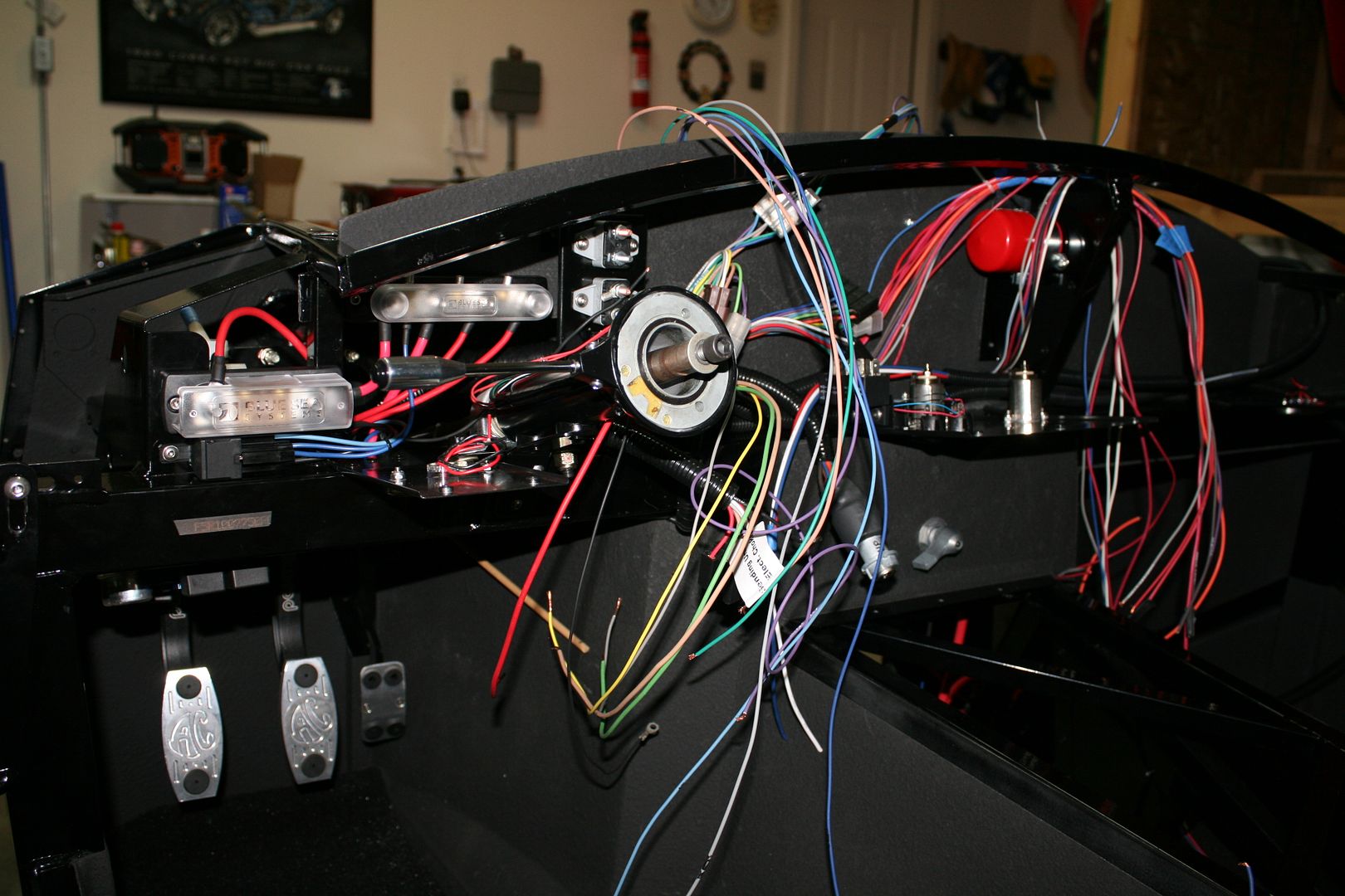
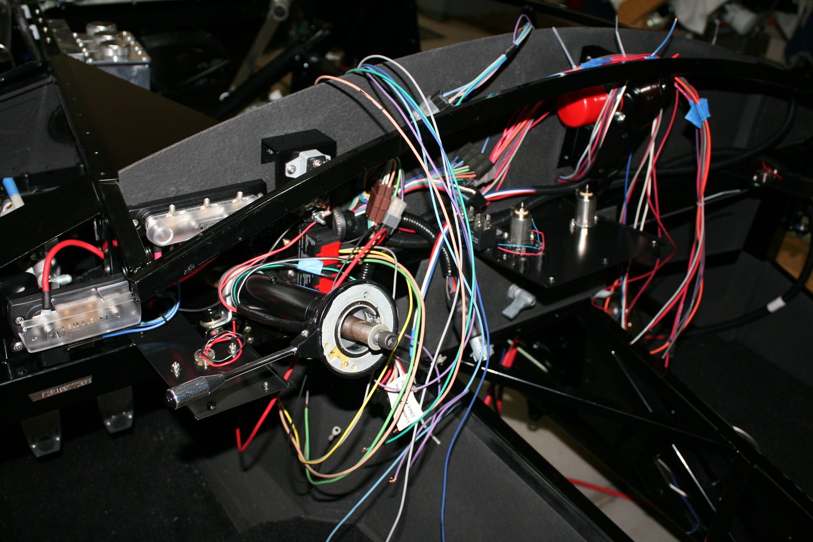
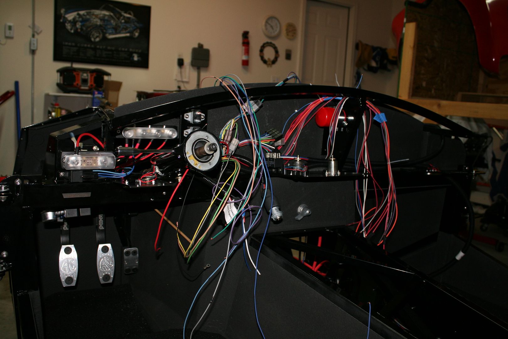
I now have all the branches mounted (main, front, back, dash, etc.). Brake light, clutch safety and main ground wires mounted. Have the MSD ignition box mounted on the firewall. I found several recommendations from MSD and others that an MSD filter capacitor on the MSD box provides good protection and could prevent failures due to voltage spikes or whatever. So got one and its mounted right behind the MSD box on the firewall brace. Both the +12V and ground for the MSD box go through the filter capacitor. I made a panel to mount the American Autowire headlight module and two circuit breakers. On the dash center brace panel I mounted two more relays (fog/running lights, headlight on chime), two switches (PS cut-off and ignition immobilizer), and two 12V aux outlets. I have a smaller dash brace panel at each end of the dash. Each has an LED downlight for the footwells that will be attached to the courtesy light circuit. The main work left is to complete all the point-to-point wiring. The dash is done and ready to plug in.
All the wiring is being done with a decent crimper, a light touch of solder on the crimp (Let's not debate that please. I have a solder station and am pretty experienced with it from my R/C days...), and adhesive shrink sleeving. Should be durable and reliable.
The last thing I did tonight was lay out the wiring for the Freddies PS setup. Finally decided where Im going to mount the breaker and relay. With those in place I can now finish up the main power wiring in the engine compartment. I'm going to wait until the engine is installed to bring the rest of the wires into the engine compartment. Like hookups for the various senders, choke, fan, etc. That way they're in exactly the right place through the firewall and as hidden as possible.
Snapped a few pictures. Looks way worse than it is (really). In fact, looking at it this way doesnt seem that I accomplished too much.
Bus bar and mega fuse before hooking anything up. Each has an included cover, visible in the next pictures.
Lots of loose wires.
Build 1: Mk3 Roadster #5125. Sold 11/08/2014.
Build 2: Mk4 Roadster #7750. Sold 04/10/2017.
Build Thread
Build 3: Mk4 Roadster 20th Anniversary #8674. Sold 09/07/2020.
Build Thread and
Video.
Build 4: Gen 3 Type 65 Coupe #59. Gen 3 Coyote. Legal 03/04/2020.
Build Thread and
Video
Build 5: 35 Hot Rod Truck #138. LS3 and 4L65E auto. Rcvd 01/05/2021. Legal 04/20/2023.
Build Thread. Sold 11/9/2023.
 Posting Permissions
- You may not post new threads
- You may not post replies
- You may not post attachments
- You may not edit your posts
-
Forum Rules

Visit our community sponsor


 Reply With Quote