Boig Motorsports

Visit our community sponsor

Thanks Thanks:  5
Likes Likes:  2
Page 11 of 22 FirstFirst ... 91011121321 ... LastLast
Results 401 to 440 of 872

Thread: Carl's Mk 4 Roadster Build

  1. #401
    Carl carlewms's Avatar
    Join Date
    May 2012
    Location
    Nokesville, VA
    Posts
    1,125
    Post Thanks / Like

    Oll Pressure Sensor Installation

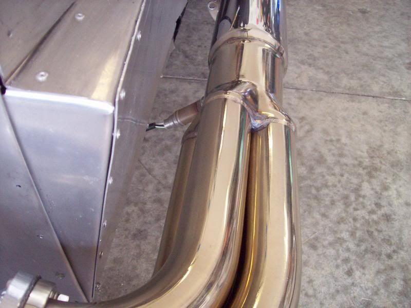
    The oil pressure sensor on 302 SBF is on the DS just forward of the oil filter. The pressure sensor is too big to fit directly into the location because of the oil filter. A common problem solved by some with brass fittings but I wanted something stronger than brass for this critical part.


    Summit sells a Scott Drake Oil Pressure Sending Extension (Part #SDK-C2OZ-9B339) made of zinc coated steel. Before installation it was treated with SharkHide. It came in 1/4" NPT at both ends and the sensor is 1/8" NPT so I had to add a coupler to make the transition.

    Here is the final installation with the sensor wiring connected.


    Carl
    Mk 4 Roadster
    October 25, 2012 - Kit Arrives
    April 8, 2013 - Build Starts
    August 23, 2015 - Rolling Chassis/Engine & Transmission Installed
    March 26, 2016 - Go Cart

  2. #402
    Carl carlewms's Avatar
    Join Date
    May 2012
    Location
    Nokesville, VA
    Posts
    1,125
    Post Thanks / Like

    Parking Brake Handle Assembly - Revisited

    I mocked up my modified parking brake assembly months ago but I had not protected the parts from corrosion .... Now was the time.


    I finished painting the parts of the modified parking brake assembly and put it back together. The parts, which are exposed in the transmission tunnel, were painted with 2 coats of POR-15 and the topped with 2 coats of Eastwood's Detail Grey Bare Metal Replication paint.

    The fully assembled parking brake lever ...


    The modified arms are extended which allows the cables to go above the 4" cross member instead below it as designed by FFR (where it actually rubs along the bottom of the tube).
    Mk 4 Roadster
    October 25, 2012 - Kit Arrives
    April 8, 2013 - Build Starts
    August 23, 2015 - Rolling Chassis/Engine & Transmission Installed
    March 26, 2016 - Go Cart

  3. #403
    Carl carlewms's Avatar
    Join Date
    May 2012
    Location
    Nokesville, VA
    Posts
    1,125
    Post Thanks / Like

    More on the Parking Brake Handle Assembly

    After a little work on Tuesday evening I finally got the parking brake fitted on the PS of transmission tunnel. It's a little more difficult to do on with the transmission and aluminum in place ... but with a little work from underneath the car it was accomplished.


    After reconnecting the cable clevis to the extended arms on the assembly I treated the ends with heat shrink.


    I installed a lock washer on the clevis pin just to keep it tight against the clevis ...


    The brakes lock the rear wheels with about 3-4 clicks on the handle with plenty of adjustability as the cables stretch...that is until I broke the stops at the end of the cables at the brake (more on that later).

    I did expand the opening a little to allow easier access to the bolts and nuts during installation. One aspect of side mounting the brake handle I don't particularly care for is how tight it fits up against the side of the tunnel; on the next build I will modify the mount or assembly slightly to allow the handle to point slightly away from the tunnel side.


    After getting it mounted I added a small patch to the access and covered the entire tunnel side in Dynamat.


    With everything in place access to the T5 transmission fill plug is a little difficult. Like others I decided to drill a hole to allow direct access to the plug with a 1/2" socket.


    During the process of moving the handle to check to see if it was adjusted I managed to pop off the end stops on each cable at the caliper ... a real PIA ... I will have to reinstall new internal cables to make it all work again ...

    Carl
    Mk 4 Roadster
    October 25, 2012 - Kit Arrives
    April 8, 2013 - Build Starts
    August 23, 2015 - Rolling Chassis/Engine & Transmission Installed
    March 26, 2016 - Go Cart

  4. #404
    Carl carlewms's Avatar
    Join Date
    May 2012
    Location
    Nokesville, VA
    Posts
    1,125
    Post Thanks / Like

    Parking Brake Repair ...

    Repairing the parking brake cable ... Backtracking a bit, when I installed the handle assembly and tested it, the ball ends on the FFR supplied cables failed, i.e. popped right off. The Lokar version is much more robust.


    The directions say to install outer housing first and then run the inner wire through outer housing; which is what got me in trouble last time. I gooned up the PS cable on the previous attempt because I could not feed the inner wire through the rather tortuous path to the handle to the point where I could not get the darn thing out of the outer housing. Here are the steps I used to avoid the problem I had earlier:

    1. Laid out the cable and removed the inner wire from the outer housing;
    2. Installed the backing plate fitting into the backing plate bracket (left loosely fitted)
    3. Fed the outer housing through to the cable housing adjuster;
    4. Measure the amount to cut off the outer housing; in this case 32";

    Here is where I deviated from the Lokar instructions.

    5. Pull the outer housing back out of the car and, using a cut off wheel, cut to length;
    6. Install the stainless steel clevis on the brake cable ball (I had to expand the clevis to get the ball fully seated);


    7. Lube up the sleeve and feed the internal cable through the sleeve;
    8. Hook the clevis into the external brake arm (the arm had to be opened up a little to get it to fit);


    8. Route the cable to the cable housing adjuster (this was a little harder to do);

    An Adel Clip was installed to keep the cables away from the drive shaft ....


    9. Slide the ferrule from the kit on to the end of the housing and feed into the cable housing adjuster; and,
    10. Attach the two cables through the cable block pulling as much slack out of the cable as possible.

    Here is what it looks like under the car before the slack was taken out of the cables...


    The brake engages with about three "clicks" on the handle. There is plenty of room for adjustment for cable stretch.
    Mk 4 Roadster
    October 25, 2012 - Kit Arrives
    April 8, 2013 - Build Starts
    August 23, 2015 - Rolling Chassis/Engine & Transmission Installed
    March 26, 2016 - Go Cart

  5. #405
    Carl carlewms's Avatar
    Join Date
    May 2012
    Location
    Nokesville, VA
    Posts
    1,125
    Post Thanks / Like

    Trying to Finish the Dash .... And Start Up Preps

    I headed out to the Olde Goat garage determined to finish up the dash and wiring ... but I ended up doing the following:

    I installed 3 mounting tabs on the underside of the dash hoop. One is center lined and the other two are at the ends about 1 in from the end. The tabs were cut from 1 " angle aluminum and one edge trimmed to 3/4" to fit on the dash hoop. After priming, they were top coated with rattle can gloss black.


    I won't determine the final dash position until I can test fit the body to determine the top of the dash location. For the first start and go kart I will use some Velcro to keep it temporarily ... or maybe permanently in place.

    As another step to first start, I checked all the coolant fittings tight and put 2 gallons of distilled water in the system...I need more distilled water. After emptying a gallon jug of water...I now had a container to mix the oil for the transmission.


    Gordon Levy recommended a 2:1 mixture of synthetic ATF transmission fluid to synthetic gear oil for the Super Alloy T-5 transmission (2.75 quarts). To fill the transmission the shift lever cover was removed (before filling I cleaned the gasket material off the cover and transmission) and removed the fill plug on the PS of the transmission. Using a funnel I slowly filled the transmission to just below the fill plug and then buttoned it all up with new black gasket maker.


    Next filling the engine oil ... I put 6 quarts of Castrol 10W40 oil in the engine which, after sitting for awhile was about 2/3rds up between the marks on the dipstick. Gordon recommends switching to synthetic (Mobil 1 5W30) after a couple of thousand miles on the engine.
    Mk 4 Roadster
    October 25, 2012 - Kit Arrives
    April 8, 2013 - Build Starts
    August 23, 2015 - Rolling Chassis/Engine & Transmission Installed
    March 26, 2016 - Go Cart

  6. #406
    Carl carlewms's Avatar
    Join Date
    May 2012
    Location
    Nokesville, VA
    Posts
    1,125
    Post Thanks / Like

    More Startup Preps ....

    When we arrived home the order from McMaster Carr had arrived. While checking the torque on the rear suspension components I found that the upper shock to frame bolt/nut thread engagement to be less than I liked. I ordered some longer bolts 2 3/4" instead of the 2 1/2" currently installed.


    Some have found that the axle nuts backing out particularly the DS; one fix is to install a second nut on the axle as a lock nut. These nuts arrived in the same package and, after the torque on the main nuts is checked, these will be installed and yellow paint on the "lock nut" to make an easy visual check to see if it is loosening up.


    I also ordered a tap for the high pressure side of the PS rack to clean up the threads; it worked. I was able to get the high pressure fitting into the rack .... at last. This turned out to be only the first struggle in getting the hydraulic lines installed.

    The connections at the power steering pump were made up and I filled the reservoir with about 1/2 qt of Quaker State power steering fluid until I can burp it during first start. The next morning I found the most of hydraulic fluid I put in the reservoir on th garage floor
    Mk 4 Roadster
    October 25, 2012 - Kit Arrives
    April 8, 2013 - Build Starts
    August 23, 2015 - Rolling Chassis/Engine & Transmission Installed
    March 26, 2016 - Go Cart

  7. #407
    Senior Member DaleG's Avatar
    Join Date
    Mar 2013
    Location
    Prescott, AZ; formerly from the Bay Area
    Posts
    829
    Post Thanks / Like
    Quote Originally Posted by carlewms View Post
    The next morning I found the most of hydraulic fluid I put in the reservoir on th garage floor
    Ouch!!! Been there too.
    SOLD 03/2013: MK II #5004: 5.0 EFI: 8.8, 3.55, E303, TW heads, GT40 intake, 24#, 70mm MAF

    Ordered MK IV Coyote Complete Kit.

  8. #408
    2bking's Avatar
    Join Date
    Jul 2013
    Location
    Garland, Texas
    Posts
    799
    Post Thanks / Like
    Quote Originally Posted by carlewms View Post
    The next morning I found the most of hydraulic fluid I put in the reservoir on th garage floor
    It took three months for mine to dump the fluid a few drips at a time from the remanufactured rack. At first start I had the lines hooked up backwards and blew something internal. I decided the easiest way to fix it was to replace the rack rather than try to rebuild it.
    King
    Roadster #8127, ordered 7/12/13, received 9/11/13
    http://thefactoryfiveforum.com/showt...4-Coyote-Build

  9. #409
    Senior Member DaleG's Avatar
    Join Date
    Mar 2013
    Location
    Prescott, AZ; formerly from the Bay Area
    Posts
    829
    Post Thanks / Like
    King, what rack did you end up with? Lock-to-lock turns?
    SOLD 03/2013: MK II #5004: 5.0 EFI: 8.8, 3.55, E303, TW heads, GT40 intake, 24#, 70mm MAF

    Ordered MK IV Coyote Complete Kit.

  10. #410
    2bking's Avatar
    Join Date
    Jul 2013
    Location
    Garland, Texas
    Posts
    799
    Post Thanks / Like
    Quote Originally Posted by DaleG View Post
    King, what rack did you end up with? Lock-to-lock turns?
    2.5, PM sent
    King
    Roadster #8127, ordered 7/12/13, received 9/11/13
    http://thefactoryfiveforum.com/showt...4-Coyote-Build

  11. #411
    Carl carlewms's Avatar
    Join Date
    May 2012
    Location
    Nokesville, VA
    Posts
    1,125
    Post Thanks / Like

    Finishing Up Firewall Bulkhead Connections

    Today I worked on finishing the connections from the firewall side to the dash connectors making some progress on connecting the switched power to the seat heaters and un switched power to the clock, DS and PS lights, the 12v DC plug and the USB plug.

    I also got the other end of the bulkhead connector wired up with the existing sensor wires from the engine:

    Tachometer/MSD RPM Signal
    Voltage (Alternator)
    Coolant Temperature and Ground
    Oil Temperature and Ground
    Oil Pressure and Ground
    Fuel Level and Ground


    I also went through all the wiring circuits to verify the connections and wiring diagrams. As I go through all of this again, I've come to the realization that I probably made some of the wiring just a wee bit too redundant ... and therefore complicated.
    Mk 4 Roadster
    October 25, 2012 - Kit Arrives
    April 8, 2013 - Build Starts
    August 23, 2015 - Rolling Chassis/Engine & Transmission Installed
    March 26, 2016 - Go Cart

  12. #412
    Carl carlewms's Avatar
    Join Date
    May 2012
    Location
    Nokesville, VA
    Posts
    1,125
    Post Thanks / Like

    More Work on the Power Steering Hoses

    After a complete failure trying to installing standard power steering hoses from a Mustang ... I freakin gave up. I had difficulty getting the fittings in the rack , my additional bends in the tubes looked like I had banged the out with a ball peen hammer and ultimately leaks on the actual fitting between the collar and the hose, all caused by "operator error"... All after about $150 in parts that didn't work.


    I purchased all the parts from Breeze ... which I should have done in the first place.

    The SS hose.... Breeze sells it by the foot.


    Two straight fittings were used on the rack end with a 9/16"-18 to 06AN adapter fitting on the high pressure side and 5/8"-18 to 06N adapter fitting on the return side. On the threaded side these have a robust looking rubber "o" ring, i.e. no Teflon which, with proper lubrication before installing and not over tightening, should remain intact.


    At the pump end the high pressure side is attached to the pump with a 90 deg elbow on the high pressure hose fitting with a 5/8"-18 to 06AN adapter.


    The low pressure return line is attached with a standard hose clamp.

    Before leaving on business travel I assembled ... Or at least I think I assembled my first leak proof 06AN fitting. I reviewed every You Tube and forum post I could find on this type of fitting ...well not "every" but a lot of them. More on my battles with the first attempt in the next post.
    Last edited by carlewms; 01-02-2016 at 05:23 PM.
    Mk 4 Roadster
    October 25, 2012 - Kit Arrives
    April 8, 2013 - Build Starts
    August 23, 2015 - Rolling Chassis/Engine & Transmission Installed
    March 26, 2016 - Go Cart

  13. #413
    Carl carlewms's Avatar
    Join Date
    May 2012
    Location
    Nokesville, VA
    Posts
    1,125
    Post Thanks / Like

    Final Power Steering Hose Installation ... I Hope

    With the arrival of the 5/8-18 to 06AN from Breeze I was able to finish the installation of the power steering hoses.

    After trying to fit the 90 deg elbows at the rack end .... without any real success, I ended up using the straight line fittings on the rack end. I just could not find a way to get the fittings aligned with the adapters to properly screw them down.


    All the threaded fittings went in fine ...

    The clamped end of the return hose leaked immediately upon putting the Honda power steering fluid. The hose ID was much smaller than the connection OD on the pump; I had tried to expand the Teflon and had split causing the leak under the clamp.

    Ultimately the only fix I could fine was to strip back the SS braid, heat the Teflon, and then expand and install it while still hot. It doesn't look very pretty right now so I will have to clean it up a bit. It doesn't leak; so functionally it works.


    No Leaks after sitting full for the last two weeks ...
    Mk 4 Roadster
    October 25, 2012 - Kit Arrives
    April 8, 2013 - Build Starts
    August 23, 2015 - Rolling Chassis/Engine & Transmission Installed
    March 26, 2016 - Go Cart

  14. #414
    Not a waxer Jeff Kleiner's Avatar
    Join Date
    Feb 2011
    Location
    Bloomington, Indiana
    Posts
    8,067
    Post Thanks / Like
    You've got it Carl! I've done PS on several cars and used the Breeze fittings & hose on all but the first (and would have on that one too had I known)---can't beat it! Yes, you need to use straight fittings at the rack. I also do the 90 at the pressure side of the pump. Yeah, the nipple on the return side at the pump is a bear. I use a heat gun and tapered punch to slightly expand the Teflon hose. A suggestion; rather than a worm drive type clamp use a fuel injection hose style like this...


    ...they won't "crawl" and cut into the Teflon when tightened.

    Cheers,
    Jeff

  15. #415
    Carl carlewms's Avatar
    Join Date
    May 2012
    Location
    Nokesville, VA
    Posts
    1,125
    Post Thanks / Like
    Jeff,

    Thanks for the words and the suggestion. I will pick up some my next trip to the auto parts store.

    Carl
    Mk 4 Roadster
    October 25, 2012 - Kit Arrives
    April 8, 2013 - Build Starts
    August 23, 2015 - Rolling Chassis/Engine & Transmission Installed
    March 26, 2016 - Go Cart

  16. #416
    Senior Member CraigS's Avatar
    Join Date
    Feb 2011
    Location
    Blacksburg, Va
    Posts
    4,728
    Post Thanks / Like
    looks like you are getting close. Pls let me know when you plan a start so I can be there.
    FFR MkII, 408W, Tremec TKO 500, 2015 IRS, DA QA1s, Forte front bar, APE hardtop.

  17. #417
    Carl carlewms's Avatar
    Join Date
    May 2012
    Location
    Nokesville, VA
    Posts
    1,125
    Post Thanks / Like
    Craig,

    Absolutely ... I am now pushing for the 16th or 17th.

    I am waiting for my side pipes to come back; I still need to work out a time to bring my DS header over to get the bung welded on.

    Thanks,

    Carl
    Mk 4 Roadster
    October 25, 2012 - Kit Arrives
    April 8, 2013 - Build Starts
    August 23, 2015 - Rolling Chassis/Engine & Transmission Installed
    March 26, 2016 - Go Cart

  18. #418
    Junior Member
    Join Date
    Nov 2014
    Posts
    11
    Post Thanks / Like
    I was a big VW guy also. Have you got rims for your roadster yet?

  19. #419
    Senior Member dallas_'s Avatar
    Join Date
    Feb 2011
    Location
    Dallas, TX
    Posts
    449
    Post Thanks / Like
    Blog Entries
    2
    Coming along nicely. You will like the power steering.

    Still on for TCC?
    FFR 7123 tilt front, Levy 5link/wilwoods/LCA's, webers.
    SL-C, LS3 525, Mendeola SDR5,

  20. #420
    Carl carlewms's Avatar
    Join Date
    May 2012
    Location
    Nokesville, VA
    Posts
    1,125
    Post Thanks / Like
    Dallas,

    Thanks. I am registered for TCC and look forward to having my car there this year ... At last!
    Mk 4 Roadster
    October 25, 2012 - Kit Arrives
    April 8, 2013 - Build Starts
    August 23, 2015 - Rolling Chassis/Engine & Transmission Installed
    March 26, 2016 - Go Cart

  21. #421
    Carl carlewms's Avatar
    Join Date
    May 2012
    Location
    Nokesville, VA
    Posts
    1,125
    Post Thanks / Like

    Electrical System Complete ... At Least for First Start

    The dash wiring has been finally completed ... At least enough to go to first start.

    After verifying all the pin connections on the bulkhead connection, the locations to centralize the grounds, switched and unswitched power behind the dash. These terminals are mounted on the inside of the firewall so as not to interfere with a future heater installation.


    The bulkhead connector is to the right of the power terminal.

    Ground Terminal: For the grounds I used the same terminal used elsewhere in the car. The grounds required from the under dash switches, lights and clock are consolidated on the terminal as well as the main grounding strap from the dash wiring.


    Power Terminal: For the switched power (powered off the front POWERCELL when the ignition switch is in the "ignition" position) is on the left. The unswitched power (powered directly from the battery via the mega fuses on the PS F-Panel) provides all unswitched power behind the dash.


    The connections to the dash are:

    1. MASTERCELL Inputs: These connect switches to the MASTERCELL to provide low voltage inputs from all the dash switches except the wiper motor;
    2. Gauges: Connects the sensor wiring from the gauges to the gauge sensors;
    3. Gauge Power: This provides power for the gauge dials, lights and indicator lights;
    4. Ground; and,
    5. Windshield Wipers.

    Here is a photo showing the four Molex connections; a long ground strap connects to a ground terminal on the firewall. All wires are labeled except the MASTERCELL wiring which is color-coded to their controlling switches on the dash and other controlling components (like the brake light switch).


    All the wires were wrapped in braided wire wrap and labeled with their function.


    The aux dash also has one Molex connector for all wiring going to the MASTERCELL and power for the lights and power sources (dual USB ports and 12V power plugs) and will have a second for the seat warmer switches (to be installed later).


    There is enough slack in the harness to pull the dash out of the way for easy access.

    Finishing up the electrical work for startup, the ground terminal board was grounded to the 4 by 4 frame and checked for continuity and the DS foot box light was installed and wired up to come on when the door is opened.


    Please note the "ventilation" I inadvertently provided during two attempts (both failed) to drill the properly sized hole for the large sheet metal I used to attach the ground to the frame.
    Mk 4 Roadster
    October 25, 2012 - Kit Arrives
    April 8, 2013 - Build Starts
    August 23, 2015 - Rolling Chassis/Engine & Transmission Installed
    March 26, 2016 - Go Cart

  22. #422
    Carl carlewms's Avatar
    Join Date
    May 2012
    Location
    Nokesville, VA
    Posts
    1,125
    Post Thanks / Like

    First Start and Go Cart Preparations Continue

    Some miscellaneous items completed...

    1. The gear shift lever installed;
    2. The RT Turn Signal modified and installed;
    3. The front suspension greased up;
    4. Checking the torque on suspension in progress (the batteries on the torque wrench and went out so it will get finished tomorrow; and,
    5. Coolant system topped off with distilled water.

    https://im1.shutterfly.com/media/47a...D550/ry%3D400/
    Mk 4 Roadster
    October 25, 2012 - Kit Arrives
    April 8, 2013 - Build Starts
    August 23, 2015 - Rolling Chassis/Engine & Transmission Installed
    March 26, 2016 - Go Cart

  23. #423
    Carl carlewms's Avatar
    Join Date
    May 2012
    Location
    Nokesville, VA
    Posts
    1,125
    Post Thanks / Like

    Headers and Side Pipes Part 1

    Thanks to a local CACC member Craig Stuard, the bung for the oxygen sensor is welded on to the DS header.


    I received the side pipes back from HTC Racing in Wareham, MA coated in "chrome" ceramic that matches the headers.

    Their price included shipping to and from their facility as well as preparing the steel side pipes for coating.

    The packaging was superb ...


    and the side pipes look great ...


    Carl
    Mk 4 Roadster
    October 25, 2012 - Kit Arrives
    April 8, 2013 - Build Starts
    August 23, 2015 - Rolling Chassis/Engine & Transmission Installed
    March 26, 2016 - Go Cart

  24. #424
    Carl carlewms's Avatar
    Join Date
    May 2012
    Location
    Nokesville, VA
    Posts
    1,125
    Post Thanks / Like

    The Tale of Two Bungs ...

    In the previous post I thought I had everything ready to install on the engine ... I thought WRONG.

    And herein starts the tale of the two bungs ...

    After carefully (we thought) selected the location on the 3rd pipe back on the DS, a friend welded the bung in place. After fitting it on the cylinder head, the bung ended up exactly below the steering shaft and without sufficient clearance to install the oxygen sensor. Damn ... We had not accounted for the tubes shifting up when the header was actually installed on the head. I needed to relocate the bung about 1.5 inches farther down the pipe (so it sticks up between the steering shaft and the 3/4 " square tube without any interference.


    I had to get at least one of the headers and side pipes mounted. The PS was much easier. Here are the results:


    The next day ... after my screaming in agony ... my friend came over and with exhaust header appropriately on the header we came up with the new improved ... not to mention usable location for the sensor.


    Well now I have a spare bung hole ... although fairly useless one at that.

    So now the tale of two bungs comes to a happy ending.
    Mk 4 Roadster
    October 25, 2012 - Kit Arrives
    April 8, 2013 - Build Starts
    August 23, 2015 - Rolling Chassis/Engine & Transmission Installed
    March 26, 2016 - Go Cart

  25. #425
    2bking's Avatar
    Join Date
    Jul 2013
    Location
    Garland, Texas
    Posts
    799
    Post Thanks / Like
    I think it will make a good place for the zerk fitting to lubricate the exhaust.
    King
    Roadster #8127, ordered 7/12/13, received 9/11/13
    http://thefactoryfiveforum.com/showt...4-Coyote-Build

  26. #426
    Carl carlewms's Avatar
    Join Date
    May 2012
    Location
    Nokesville, VA
    Posts
    1,125
    Post Thanks / Like
    King,

    I will have to get it drilled and tapped out before I mount today ... HaHa.

    Carl
    Mk 4 Roadster
    October 25, 2012 - Kit Arrives
    April 8, 2013 - Build Starts
    August 23, 2015 - Rolling Chassis/Engine & Transmission Installed
    March 26, 2016 - Go Cart

  27. #427
    Senior Member AC Bill's Avatar
    Join Date
    Feb 2011
    Location
    Vancouver Island BC Canada
    Posts
    1,878
    Post Thanks / Like
    Carl, maybe you could incorporate one of these with the unused bung..

    http://www.hotlicksexhaust.com/photos

  28. #428
    Carl carlewms's Avatar
    Join Date
    May 2012
    Location
    Nokesville, VA
    Posts
    1,125
    Post Thanks / Like
    Now that would be interesting with side pipes. I could see some interesting applications:

    1. If someone got too close to the car ... A press of the button would surely scare them away;

    2. Set up a grill on the tip when tailgating to cook the burgers and hot dogs; and last, but surely not least;

    3. Rev up and hit the button just as that nice police officer walks by after writing the speeding ticket!
    Mk 4 Roadster
    October 25, 2012 - Kit Arrives
    April 8, 2013 - Build Starts
    August 23, 2015 - Rolling Chassis/Engine & Transmission Installed
    March 26, 2016 - Go Cart

  29. #429
    Carl carlewms's Avatar
    Join Date
    May 2012
    Location
    Nokesville, VA
    Posts
    1,125
    Post Thanks / Like

    The Driver's Side Exhaust System is Finally Installed

    Last evening I got some high temperature aluminum paint and painted the welds and plug on the unused bung. It doesn't match up as well as I like but it will protect them and make them a little less obvious.

    After the well documented problems with the bungs ... tonight I got a little garage time and installed the DS exhaust header (and what a PIA it was) and the side pipe.

    My fat fingers had all sorts of trouble with the #8 cylinder screws. The first 6 took 10 minutes and the last 2 took 30 minutes plus. I had quite a bit of cleanup of the copper gasket maker which got in a lot of spaces it was not meant to go!

    It is finally starting to look like something that can move ... Swiftly.
    Mk 4 Roadster
    October 25, 2012 - Kit Arrives
    April 8, 2013 - Build Starts
    August 23, 2015 - Rolling Chassis/Engine & Transmission Installed
    March 26, 2016 - Go Cart

  30. #430
    Senior Member 2FAST4U's Avatar
    Join Date
    Feb 2011
    Posts
    1,006
    Post Thanks / Like
    Those side pipes look awesome

  31. #431
    Carl carlewms's Avatar
    Join Date
    May 2012
    Location
    Nokesville, VA
    Posts
    1,125
    Post Thanks / Like
    Here are the photos I forgot to post ...

    The twin bungs ...


    Clearance is perfect ...


    Clearance between the DS Inner Foot Box Panel and the #8 cylinder header bolts is pretty small..


    I used the standard BEK bolts but will replace after go kart with lockable versions.

    Carl
    Mk 4 Roadster
    October 25, 2012 - Kit Arrives
    April 8, 2013 - Build Starts
    August 23, 2015 - Rolling Chassis/Engine & Transmission Installed
    March 26, 2016 - Go Cart

  32. #432
    Senior Member AC Bill's Avatar
    Join Date
    Feb 2011
    Location
    Vancouver Island BC Canada
    Posts
    1,878
    Post Thanks / Like
    Carl, You know something... I'm beginning to think you just really like using the word "Bung"..

  33. #433
    Junior Member
    Join Date
    Mar 2014
    Posts
    7
    Post Thanks / Like
    Carl, I am also using EZ EFI 2.0 and am looking at my O2 sensor location. I do have a bung on my header roughly where yours is but was told by both FAST and the mechanic who sold me the EFI that I should place the O2 bung on the collector to read at least 4 cylinders, or at least 20" away from the cylinder head. So now I am considering putting the bung on the side pipe, in a less than ideal orientation due to the body.

  34. #434
    Senior Member CraigS's Avatar
    Join Date
    Feb 2011
    Location
    Blacksburg, Va
    Posts
    4,728
    Post Thanks / Like
    My thinking on O2 placement is this. Theoretically in the collector is best but there are a couple of problems w/ that on an FFR. 1- That puts the sensor maybe 30 inches from the head. All modern cars have moved the sensor as close to the head as possible to get it heated as quickly as possible. Yes I know the sensors are heated but look under the hood of your daily driver to see what I mean. 2- Unless you want to see the sensor in the collector, it will be placed well below the center of the collector where it is bound to get condensation running into it. That is not good.
    FFR MkII, 408W, Tremec TKO 500, 2015 IRS, DA QA1s, Forte front bar, APE hardtop.

  35. #435
    Junior Member
    Join Date
    Mar 2014
    Posts
    7
    Post Thanks / Like
    I agree with you Craig. I had read that condensation is less of an issue with the heated O2 sensors. I can probably get an 8 o'clock position on the collector, which is not ideal but will reduce the condensation issue somewhat. What about the limitation of reading only one cylinder with the bung on the header? My bung is actually located 4-5" closer to the head than Carl's. Isn't that too hot as well? I would rather not use the side pipe collector so don't know what to do. If I had planned earlier, I could have had stainless headers make me the Coyote style header with the bung in an ideal location.

  36. #436
    Senior Member CraigS's Avatar
    Join Date
    Feb 2011
    Location
    Blacksburg, Va
    Posts
    4,728
    Post Thanks / Like
    These camry exhaust manifold pics illustrate what I saw over the years at Lexus. This is 2001
    http://www.partsgeek.com/gbproducts/...FddahgodU0UCuw
    This is 2011
    http://www.partsgeek.com/gbproducts/...ad=47433949212
    See what I mean about the sensor getting closer to the head. I don't think you can get too close. Notice also that the newer version sure doesn't look like it flows very well.
    FFR MkII, 408W, Tremec TKO 500, 2015 IRS, DA QA1s, Forte front bar, APE hardtop.

  37. #437
    Not a waxer Jeff Kleiner's Avatar
    Join Date
    Feb 2011
    Location
    Bloomington, Indiana
    Posts
    8,067
    Post Thanks / Like
    I've done cars both ways; in one tube as well as at the collector. Know what? They run great either way! That said though I'm pretty much in agreement with Craig that there will be some compromise no matter which route you go. FWIW, here's where the sensor winds up in the collector to clear the body:


    Only visible if you look straight down between the body and pipe.

    Jeff

  38. #438
    Junior Member
    Join Date
    Mar 2014
    Posts
    7
    Post Thanks / Like
    Again, is performance compromised by O2 sensor reading only one cylinder instead of at least 4 through the collector??

  39. #439
    Out Drivin' Gumball's Avatar
    Join Date
    Feb 2011
    Location
    Blackberry Township, IL
    Posts
    2,653
    Post Thanks / Like
    Quote Originally Posted by carlewms View Post

    Well now I have a spare bung hole ... .
    I never, ever, thought I'd read that on a car forum!!!!!
    Later,
    Chris

    "There are no more monsters to fear, and so, we have to build our own."
    Mk3.1 #7074

  40. #440
    Carl carlewms's Avatar
    Join Date
    May 2012
    Location
    Nokesville, VA
    Posts
    1,125
    Post Thanks / Like
    SMV,

    I think the collective answer so far is "no". I have not done my first start (delayed because of the darn weather here in Northern Virginia) so I cannot offer any personal example to tell you.

    I will be posting my first start video ...

    It sounds like its really your choice. In my case the ECU is located where the FFR fuse panel is normally found so I have sufficient wire to connect to either one if this doesn't work out.

    Carl
    Mk 4 Roadster
    October 25, 2012 - Kit Arrives
    April 8, 2013 - Build Starts
    August 23, 2015 - Rolling Chassis/Engine & Transmission Installed
    March 26, 2016 - Go Cart

Page 11 of 22 FirstFirst ... 91011121321 ... LastLast

Posting Permissions

  • You may not post new threads
  • You may not post replies
  • You may not post attachments
  • You may not edit your posts
  •  

Stewart Transport

Visit our community sponsor