I am wrapping up terminating all of the lights, connections and switches. I certainly anticipated something to have to work through but this truly seems odd so I figured I would ask.
My build has the RF harness, RT turn signal assembly, breeze LED lights with standard kit housings. I have the breeze front battery kit with a large ground wire to the starter mounting bolt and the engine has two large ground straps. I have an aftermarket classic instruments gauge set.
The breeze LED kit came with the electronic flashers that I exchanged out simply by plugging them in and running a ground wire to both. I have a Fitech 600EFI and is wired into the fuse panel for fan and fuel pump control as directed.
When I attach the battery the instruments all light up as they should. The headlights work as they should including both low and high beam. The hazard flashers work with the exception of the passenger front light.
The anomaly here is that when I put the turn signal assembly to Right Turn position, the fuel pump kicks on and it is in a flasher type pattern, on-off-on-off.
I've looked through the wiring diagrams for awhile and I'm not sure where to start even tracking this down.
Anyone have any ideas?
Thanks again in advance.
It sounds like what I encountered with my wiring. I had a friend helping me and he discovered that the wiring from the dash harness to the front harness was miswired at the connection. He simply depinned the wire from the dash harness and put it in the correct location in the connector. All was OK then. Hope this helps.
JR
Mk4 complete kit #9059 ordered 1/19/17 delivered 3/23/17, 2015 IRS, Fortes/DART347,TKO 600, hyd clutch, P/S, 12.88 wilwood brakes front and rear, heater/defrost and vintage gauges
First start and go-cart 4/11/18. Taken To Whitby Motorcars Greensboro, N.C. 2/5/21 for body/paint
Agree about checking the harness. Sounds like maybe the green fan ground wire and one of the turn signal lights are switched around. But a separate question based on your description. You went straight from the battery ground to the engine by the starter, and then then two ground straps from the engine to the frame? So your car's entire ground circuit is going through the engine? Might be OK, but wouldn't be my choice. I'd rather see a direct ground wire to the frame next to the battery. Then go from the starter bolt to the chassis. Then another engine to frame ground strap if you like, which I agree is a good idea and I do the same thing.
Build 1: Mk3 Roadster #5125. Sold 11/08/2014. Build 2: Mk4 Roadster #7750. Sold 04/10/2017. Build Thread Build 3: Mk4 Roadster 20th Anniversary #8674. Sold 09/07/2020. Build Thread and Video. Build 4: Gen 3 Type 65 Coupe #59. Gen 3 Coyote. Legal 03/04/2020. Build Thread and Video Build 5: 35 Hot Rod Truck #138. LS3 and 4L65E auto. Rcvd 01/05/2021. Legal 04/20/2023. Build Thread. Sold 11/9/2023.
Thanks for the recommendations I’ll let you know what I find when I dig back into the wiring.
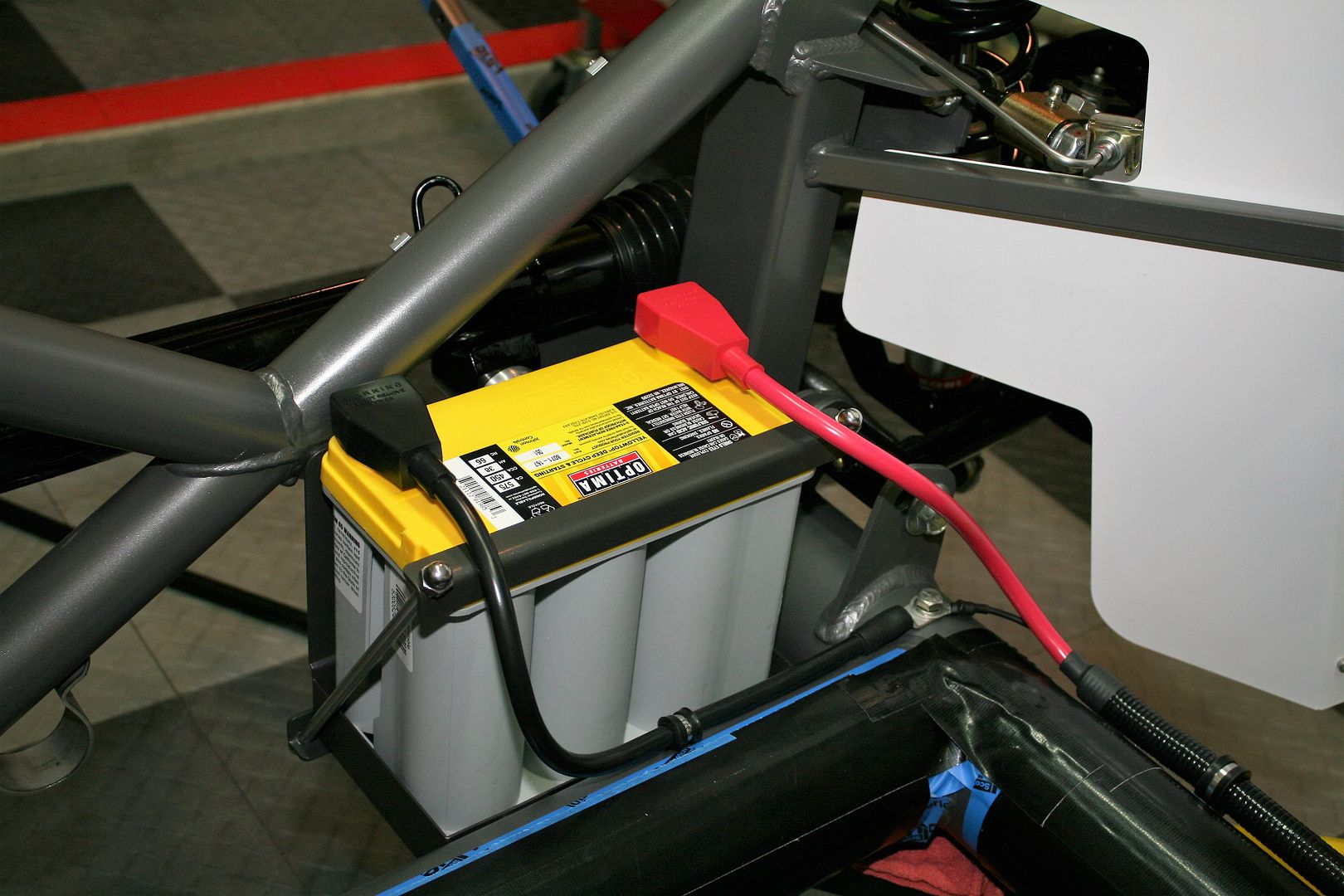
I have this 8ga jumper from the ground post to the chassis. Is that sufficient or should I look at something else too?
I believe I followed the instructions from the Breeze setup but I’ll go back through it. Maybe I missed something.
Thanks for the recommendations I’ll let you know what I find when I dig back into the wiring.
I have this 8ga jumper from the ground post to the chassis. Is that sufficient or should I look at something else too?
I believe I followed the instructions from the Breeze setup but I’ll go back through it. Maybe I missed something.
Mark typically has well thought-out and detailed instructions. So if you have it wired the way he said to, I'm sure it's probably fine. I was just struck with your scheme having the primary ground path for the entire vehicle through the engine. That jumper you pictured at the battery is OK, but hardly enough for everything. My preference is a ground cable the same gauge as the +12V cable (I use 2 gauge) bolted to a cleaned off location on the chassis right next to the battery. In this case, I also have a smaller gauge wire under there. That's the ground wire from the Coyote control pack harness that Ford was adamant had to home run to the battery ground. So that's what I did. As mentioned before, I also have two engine grounds to chassis. One from the front for the block, the other under one of the starter bolts. I've used this exact setup on every build. Not saying it's the only way. Just my preference.
Last edited by edwardb; 04-25-2020 at 08:50 PM.
Build 1: Mk3 Roadster #5125. Sold 11/08/2014. Build 2: Mk4 Roadster #7750. Sold 04/10/2017. Build Thread Build 3: Mk4 Roadster 20th Anniversary #8674. Sold 09/07/2020. Build Thread and Video. Build 4: Gen 3 Type 65 Coupe #59. Gen 3 Coyote. Legal 03/04/2020. Build Thread and Video Build 5: 35 Hot Rod Truck #138. LS3 and 4L65E auto. Rcvd 01/05/2021. Legal 04/20/2023. Build Thread. Sold 11/9/2023.
The engine needs to be grounded to the frame with a fairly heavy cable. The engine mounts have rubber or some other type of insulator that does not conduct very well, if at all. In the past I once saw an engine that was poorly grounded and the speedometer cable became the ground wire. You can imagine what that did.
Thanks again for the responses and help
This is one of my two engine grounds.
Is the green fan ground wire the thermo switch wire?
Forgive my ignorance but I’ve looked through this for a bit and must be missing the connection. How does the fan ground interact with the flasher that’s somehow controlling the fuel pump?
Just lurking on this thread, and have an observation on your pic above. Your ground cable from engine block to chassis: Two things, make sure the chassis is "clean" and a good ground (i.e. no paint under the cable lug, or a star washer for good continuity), and with engine movement in the rubber mounts, is there enough slack in that cable so that is won't bind or break under load? I know you said you had two grounds, just noting in your picture a "what if" and "how could it go wrong" question.
If Brute Force doesn't work, you're not using enough of it. Basic Stuff: MK4 Complete Kit #8439, Wilwood's, 17" Halibrands. Extra Stuff: Stainless brake and fuel lines, Breeze cooling, Battery mount, SS Roll Bar. Old Fart Stuff: Heater, Seat Heaters, Footbox Fresh Air, Stereo, Keyless ignition, Power Steering, Hyd Clutch. Young & Dumb Stuff: 427w Dart, TKO600, 3 link Moser M9/Ford 9", 3.5:1, Eaton TruTrac Posi. Graduation Thread
Thanks that’s true I didn’t think of that. That one may very well be too rigid. I had left over cable so I thought I would make a ground out of it but should probably replace with the standard flexible ground.
Originally Posted by boat737
Just lurking on this thread, and have an observation on your pic above. Your ground cable from engine block to chassis: Two things, make sure the chassis is "clean" and a good ground (i.e. no paint under the cable lug, or a star washer for good continuity), and with engine movement in the rubber mounts, is there enough slack in that cable so that is won't bind or break under load? I know you said you had two grounds, just noting in your picture a "what if" and "how could it go wrong" question.
Tomorrow will be more wire tracing.
As it stands right now the left turn signals, park lights, headlights, hazards and brake lights work.
The fuel pump is turned on by the right turn signal and hazard flashers.
Is the green fan ground wire the thermo switch wire?
There are two of the green fan thermo control wires in the harness; one on the sending unit bundle and one in the front harness with the fan power and ground. The green thermo wires are a ground trigger for the fan relay in the fuse panel. Most EFI systems have a fan control wire that is a ground signal and you can connect that to either of the wires in the RF harness to let your EFI control the fan via the existing relay.
Thanks I’ll have to look again at how I connected the EFI signal to the jumper on the fuse panel and how it may be firing the fuel pump.
Originally Posted by Papa
There are two of the green fan thermos control wires in the harness; one on the sending unit bundle and one in the front harness with the fan poser and ground. The green thermos wires are a ground trigger for the fan relay in the fuse panel. Most EFI systems have a fan control wire that is a ground signal and you can connect that to either of the wires in the RF harness to let your EFI control the fan via the existing relay.
Here are a few questions I have that might help figure out where your problem might be.
*With no lights on, Turn key on, does just your fuel pump come on?
*if yes, confirm that no turn signal lights are on.
*you say that the passenger front Hazard does not work but, does the fuel cycle on and off with the hazards on?
* when the fuel pump is turning on off with the right turn, are both right turn lights flashing as well?
Is the green fan ground wire the thermo switch wire?
Forgive my ignorance but I’ve looked through this for a bit and must be missing the connection. How does the fan ground interact with the flasher that’s somehow controlling the fuel pump?
No, they absolutely shouldn't interact. And yes, in the RF harness the two fan thermo switches are green. One of them goes through the front harness connectors. Also your front lights go through the front harness connectors. The possibility is the pins on these wires are in the wrong locations in the connector, e.g. backwards. Has happened before with RF harness connections. Just look at all the front harness connectors and confirm the color going in on one side is the same going out on the other side.
Build 1: Mk3 Roadster #5125. Sold 11/08/2014. Build 2: Mk4 Roadster #7750. Sold 04/10/2017. Build Thread Build 3: Mk4 Roadster 20th Anniversary #8674. Sold 09/07/2020. Build Thread and Video. Build 4: Gen 3 Type 65 Coupe #59. Gen 3 Coyote. Legal 03/04/2020. Build Thread and Video Build 5: 35 Hot Rod Truck #138. LS3 and 4L65E auto. Rcvd 01/05/2021. Legal 04/20/2023. Build Thread. Sold 11/9/2023.
With lights off and key on I hear the fuel pump kick and and the EFI make noise.
Key off all hazards work.
With key off and lights on with the RT assembly to the right turn signal the fuel pump is on in a flasher mode.
With key on and lights off. When I put the RT signal to right turn the hazards turn on
Key on, lights on, right turn, only passenger rear turn light is on and no fuel pump.
Thanks for trying to work me through this I appreciate it.
Originally Posted by D Stand
Here are a few questions I have that might help figure out where your problem might be.
*With no lights on, Turn key on, does just your fuel pump come on?
*if yes, confirm that no turn signal lights are on.
*you say that the passenger front Hazard does not work but, does the fuel cycle on and off with the hazards on?
* when the fuel pump is turning on off with the right turn, are both right turn lights flashing as well?
Gotcha, last night I confirmed at least on the harness connections the wires going in and out match.
Originally Posted by edwardb
No, they absolutely shouldn't interact. And yes, in the RF harness the two fan thermo switches are green. One of them goes through the front harness connectors. Also your front lights go through the front harness connectors. The possibility is the pins on these wires are in the wrong locations in the connector, e.g. backwards. Has happened before with RF harness connections. Just look at all the front harness connectors and confirm the color going in on one side is the same going out on the other side.
Need help finishing your project we can help here or at your shop.
FFR GTM #34 first GTM with working AC. 400 hp LS1 w/G50
FFR coupe 3617CP 331 Stack EFI T-5 IRS Cobra brakes, AC/heat.
Both cars by NRC, we can build (and have built) any FFR product.
We also make and sell a ton of great parts for the FFR community.
Brake kits, AC systems, #1 supplier of Team III wheels.
Havent seen anyone say it yet, so check the seating of the right rear dual contact lamp. If its in the wrong position, it can create lots of odd things to happen like what you are seeing. If it seems OK, try a regular 1157 lamp. You could have a bad LED thats backfeeding power into the ground.
Thanks again for the help.
I don’t currently have any diodes in the system.
I’ll try exchanging for the regular bulbs and see what happens. Last night I did exchange some of the LED bulbs around with the same results.
In other news , I connected my Speedo gauge and hooked up the right and left turn indicator lights exactly as shown in the diagram and now with the battery connected and headlight switch off, the parking lights are on.
I’m going to get the voltmeter out and start from the beginning. See if I can educate myself here.
Always good to remember a bad day working on the build is still an awesome day.
Check your power leads and how things are tied into the ignition switch and the function of the ignition switch itself (several examples in other threads about weird electrical behavior that turned out to be a faulty ignition switch). If you are getting power to circuits other than those in the BATT FED portion of the fuse panel when the key is off, something isn't right. Get the schematic out and be sure you understand what circuits are fed from the three sections of the fuse panel and how those relate to the ignition switch wiring. That will help a lot. Also, it always makes me worry a bit when people have made modifications to the harness at the fuse panel based on the "instructions", particularly when it comes to the relay circuits. Biggest problem there is that many don't understand how the circuit works and the instructions can't account for all the variables.
Here is a detail of how my RF fuse panel was actually wired. There is more details for the relay connections. This might help you confirm that you have tapped into the harness properly for your FiTech control of fan and fuel pump. If you do what the manual tells you to do, you are cutting the tan loop of wire that is between the +fuse and +of the coil. You would want to connect the +coil to the fitech +trigger for fuel pump. If you have done this, I do not see how your issue is happening.
You said With key on and lights off. When I put the RT signal to right turn the hazards turn on. Per Papa and this diagram, this is not right. You should not have power to the turns or fuel pump with key off. I am not familiar with the RT extra wiring so you might be doing something wrong there too. Only items that should work with key off is hazards, brakes, courtesy lights, radio memory, headlights, and cooling fan.
I agree with Boydster too, get rid of all the leds and get it all working first.
I think I tracked this down.
I switched the bulbs back to the original incandescents at the good advice of others above. With that the fuel pump stopped acting erratically.
At that point the ONLY thing not working was the front right turn signal.
When I switched the front left and right light assembly (they are wired the same) the problem follows the light.
I’ll check the internal wiring tonight.
I took apart the two front turn signals and sure enough the one I had on the passenger side was mis-wired internally. The picture below shows how the red/yellow and the green wires are opposite orientation from the correctly working light. It was more clear in reality that the orientation was backward compared to the other side than the image really shows. I simply de-pinned the red/yellow and green on the light assembly weatherpack connecters, switched them and everything is working perfect!
I have no idea why this change caused what it did. After the LED lights were switched the fuel pump acts as it should (at least now pre-start) and the lights now all work correctly after switching for the original bulbs. Next step will be to try switching back out for the LEDs and see what happens I suppose?
If anyone knows, for my own education I would certainly be interested. Just glad everything is working and all the forum members above saved me likely hours or days of trying to track this down.


 Thanks:
  Likes:


 Reply With Quote