-
07-23-2023, 10:07 AM
#161
Can you call me? Ive lost your number if you gave it to me.
-
07-28-2023, 06:34 AM
#162
Senior Member

Interior Console for overhead and dash fit-out
Quick update....
First, in my last post, I mentioned I'd be applying Lizard Shin. Well that didn't go well at all. I cleaned the cab interior with solvent and applied the Sound Control product first.... well, after drying overnight, it started to peel.... and each day as it dries more I get more peeling. The only thing I didn't do from the instructions was "rough up" the surface. The reason is I "thought" the fiberglass was rough enough.... well that was sure wrong or it was something else? Lew, from the forum, stopped by to pickup my Lizard skin sprayer and thought maybe is was some sort of release agent or a wax type substance leaching from the fiberglass? Regardless, when I take the cab off later, I'll strip it all off and try something different. I'll document all that later when the time comes.
With the cab back on the chassis, I wanted to continue my electrical connections, fitting the dash/gauges, and build my center console and overhead console.
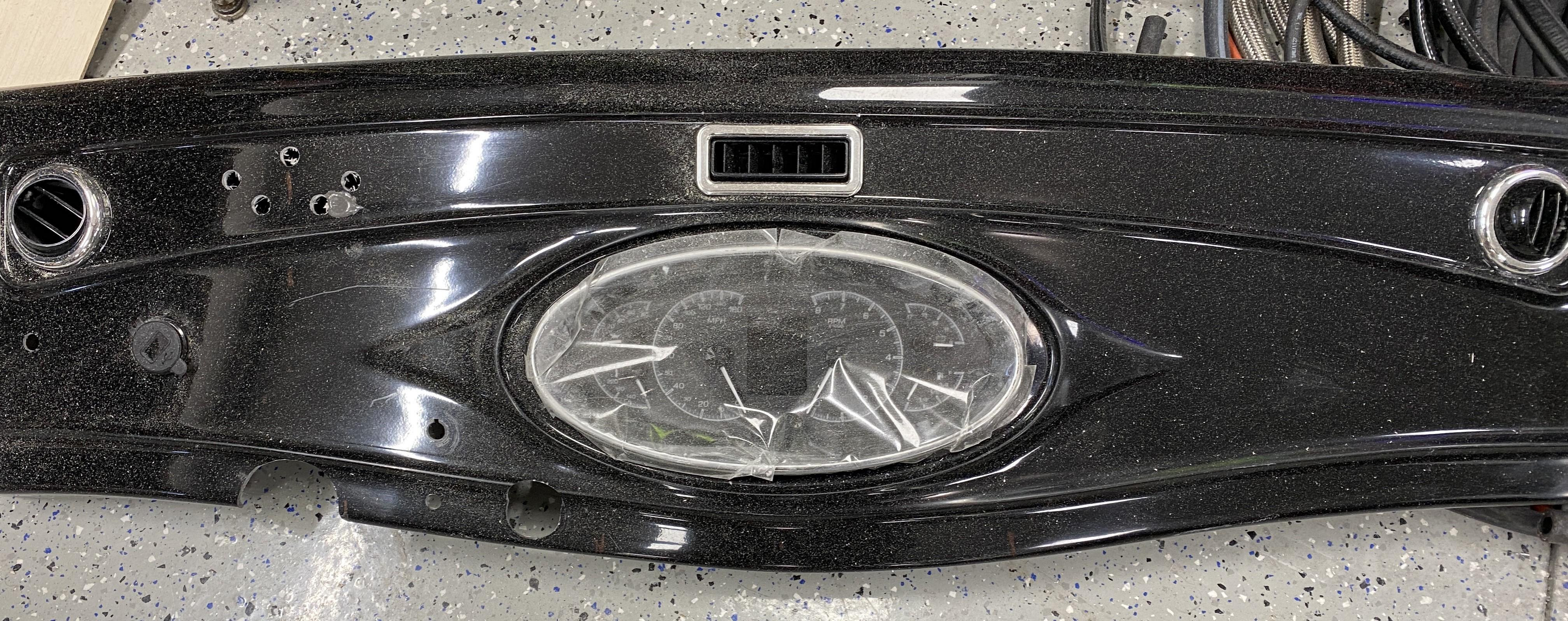
The dash was pretty easy to fit with the trimming of the 1/2" gap along the windshield area, the sides and the 1.5" diameter around the roll bar. I believe my dash is pretty clean (ignore the dust on the black fiberglass) with the fitment of the A/C vents, defroster vents, center gauge, wiper/washer switch, indicator LEDs, ignition switch, light switch, dimmer and USB.
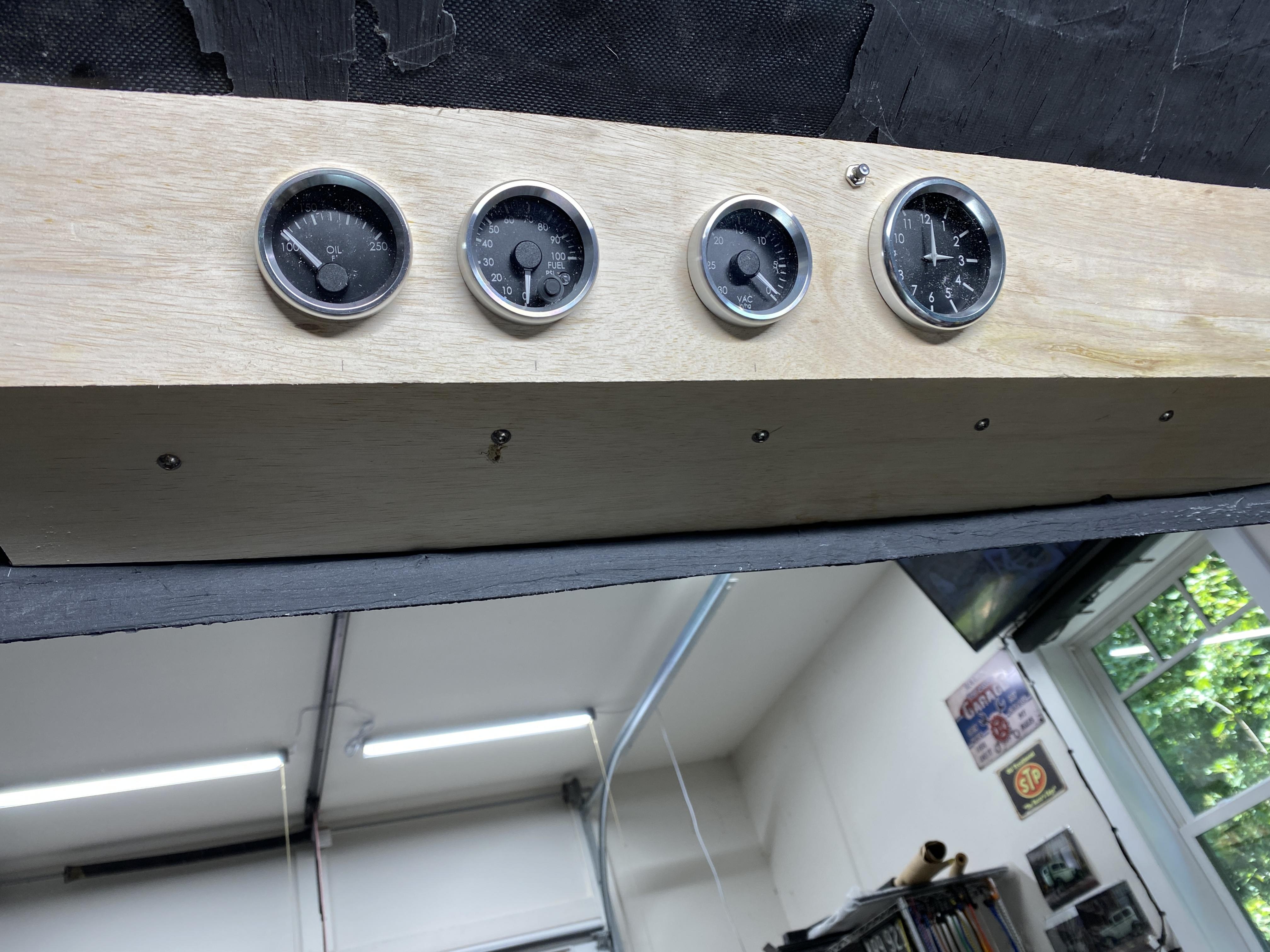
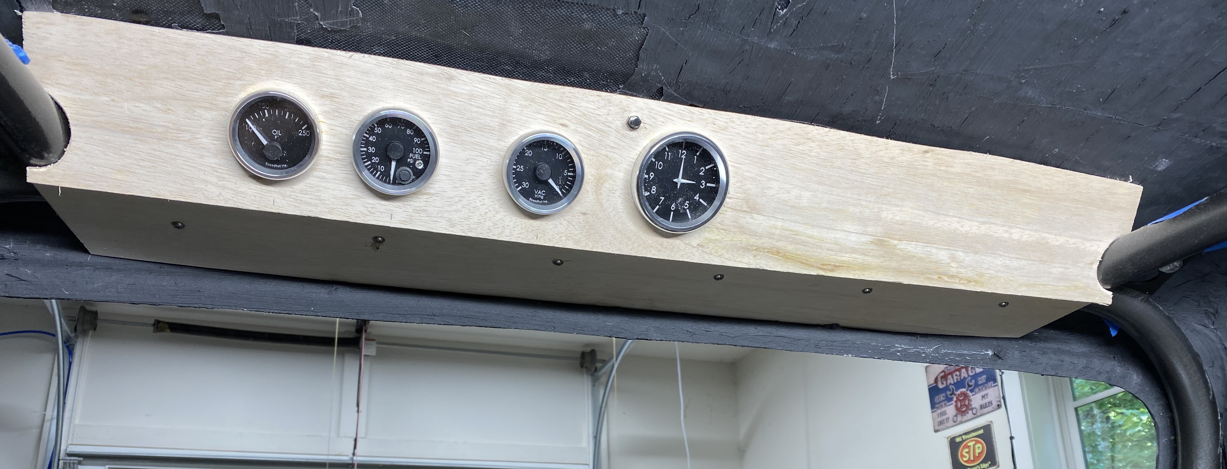
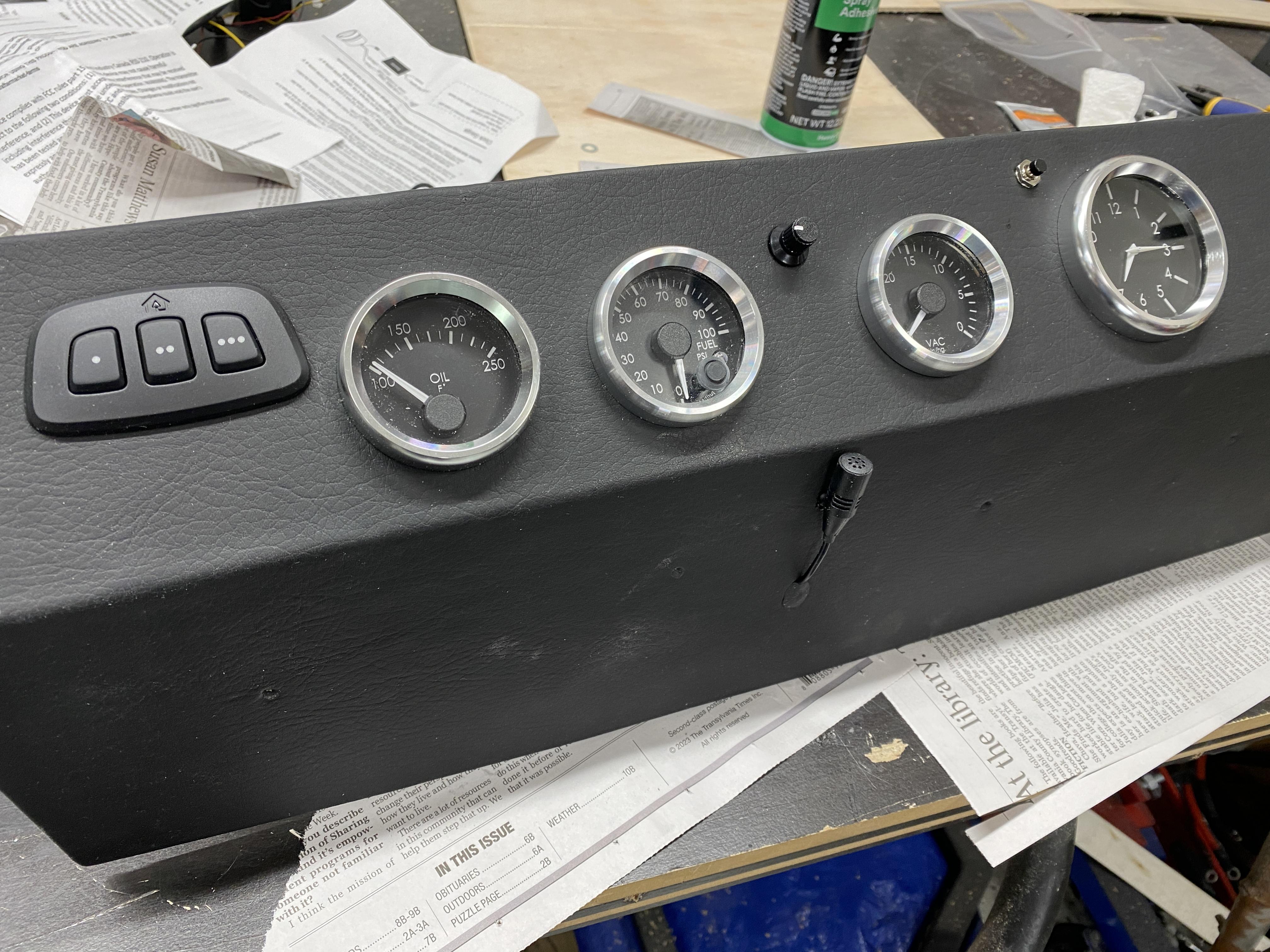
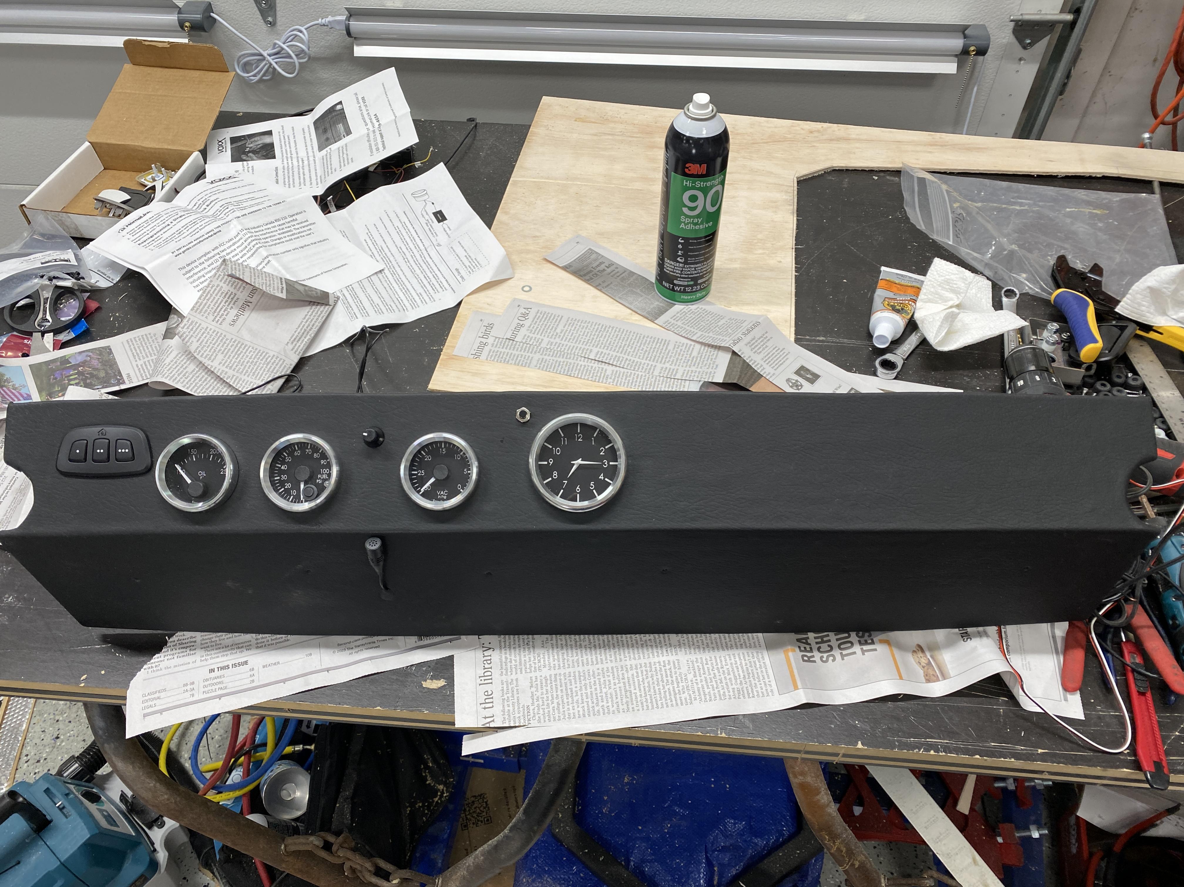
My extra gauges will go into the overhead console I'm building.... i.e., VAC, Fuel PSI, Oil Temp and Center Clock. The pics below show it in very rough form. I still need to do my cut out for the Home Link garage door opener... I'll so this to the left of the of the left most Oil Temp gauge. I'll mount a mic for mobile hand free feature connected to the stereo head unit. I'll cover the wood console with vinyl simulated leather.
The center console I'm building will house the Radio/stereo head unit, the A/C/Header controls, Window switches, E-Stopp switch, my remote Master Electric switch, Seat heater and lumbar switches, etc. I'll also have an arm rest. I'm planning on a simple security system and the bottom of the arm rest and under the main part of the console I can "hide" more components/wires. Two cup holders will also be installed into the console.
More to come,
Mark
Last edited by mkassab; 07-28-2023 at 09:33 AM.
-
07-31-2023, 05:56 AM
#163
Senior Member

Center Console building
Yesterday was spent building my center console. I'm using 3/16" Luan plywood. For the arm rest portion of the console I'm using 3 layers glued together for strength and to fill the gap between the aluminum driveshaft cover and the heavier and thicker fiberglass trans tunnel cover. The reason I wanted the strength was it needs to support the weight of a person who uses their arm to lift themselves to position them in the seat. I attached 3 - 1/4-20 rivet nuts on each side of the driveshaft tunnel to give the arm rest section a good base. At the base of the arm rest I'll put a false bottom in this part of the console.... the bottom section will be for electronic components and act as a wire way between the truck's rear and front. The top section for storage.
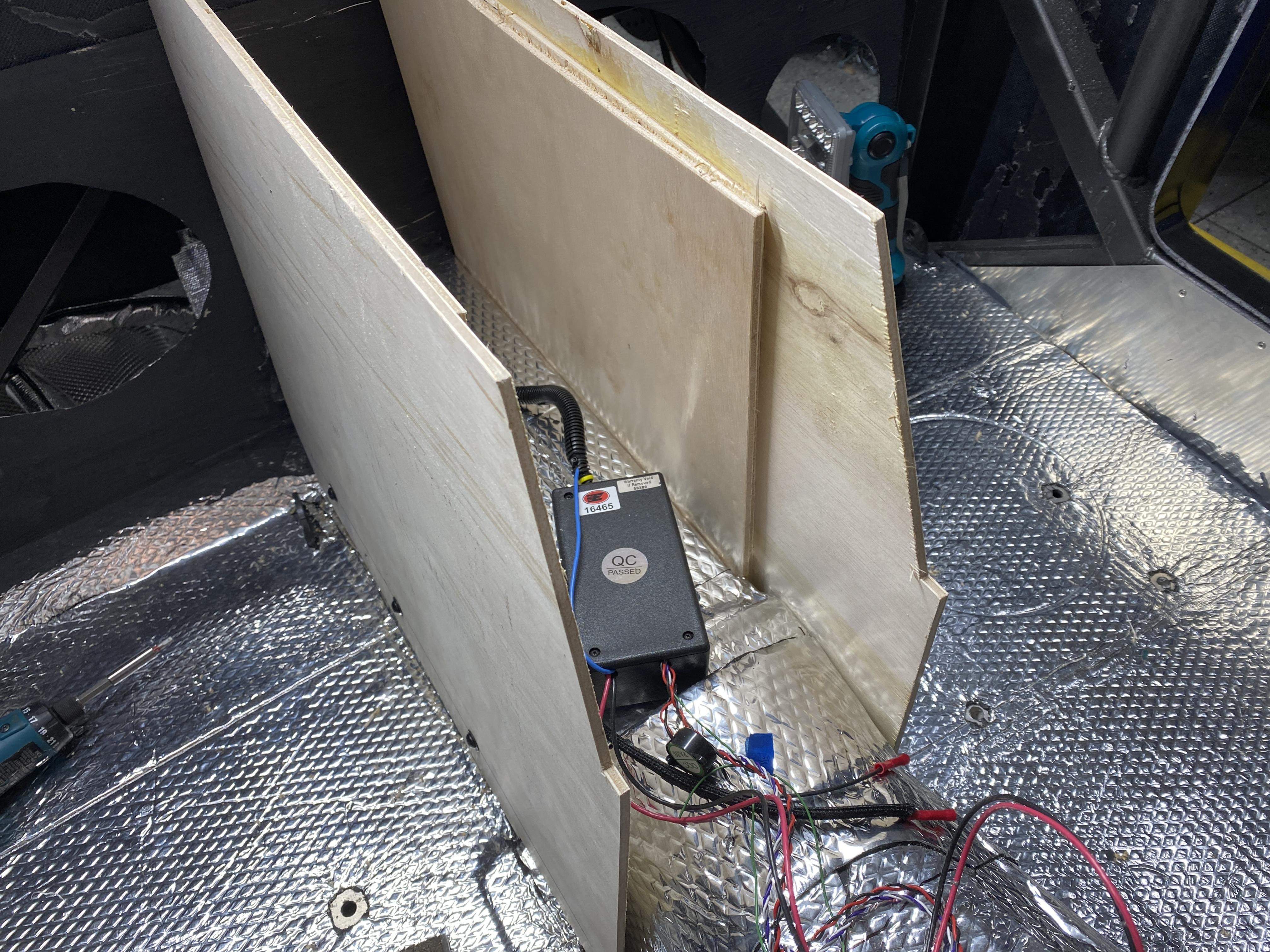
The reason I'm building in multiple sections is to allow for the angle transition from the driveshaft tunnel and the trans tunnel. Also, it's the only way to install and/or remove the console in the truck's small cab.
In the next pic, I'm adding the trans tunnel side panels and adding cross section supports between the two sections.
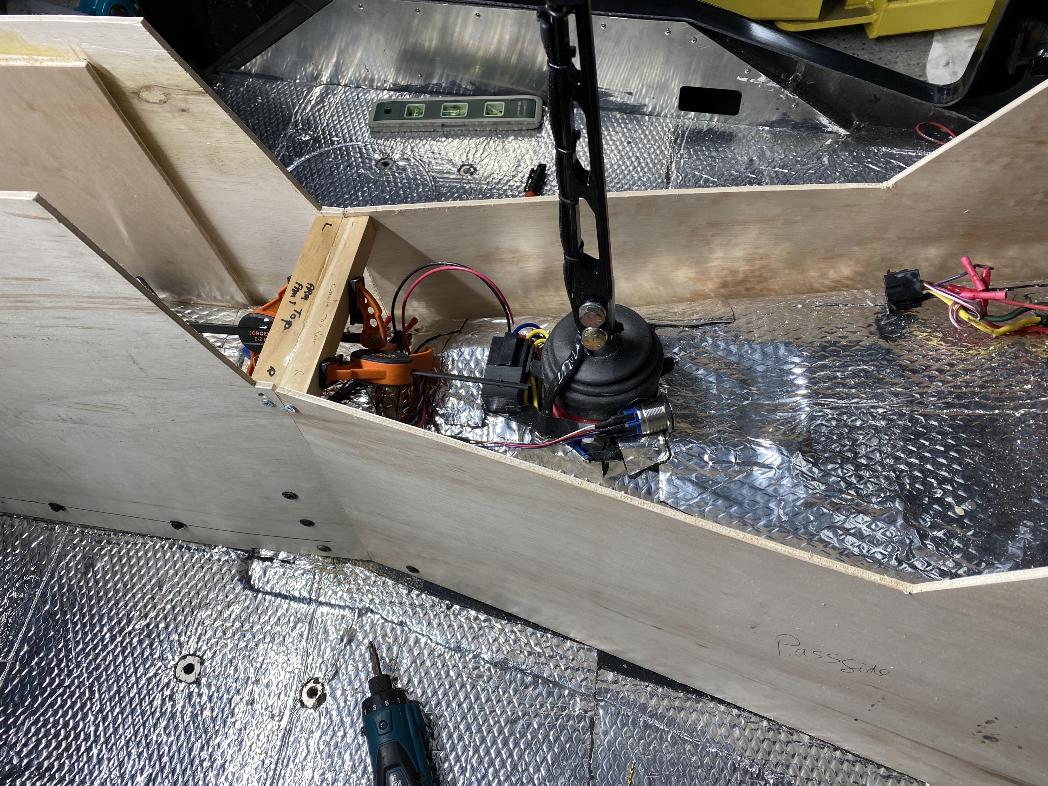
For the panel mounting to the trans tunnel, I'm using sheet metal screws through the fiberglass. Take note of the consoles fit up under the dash.
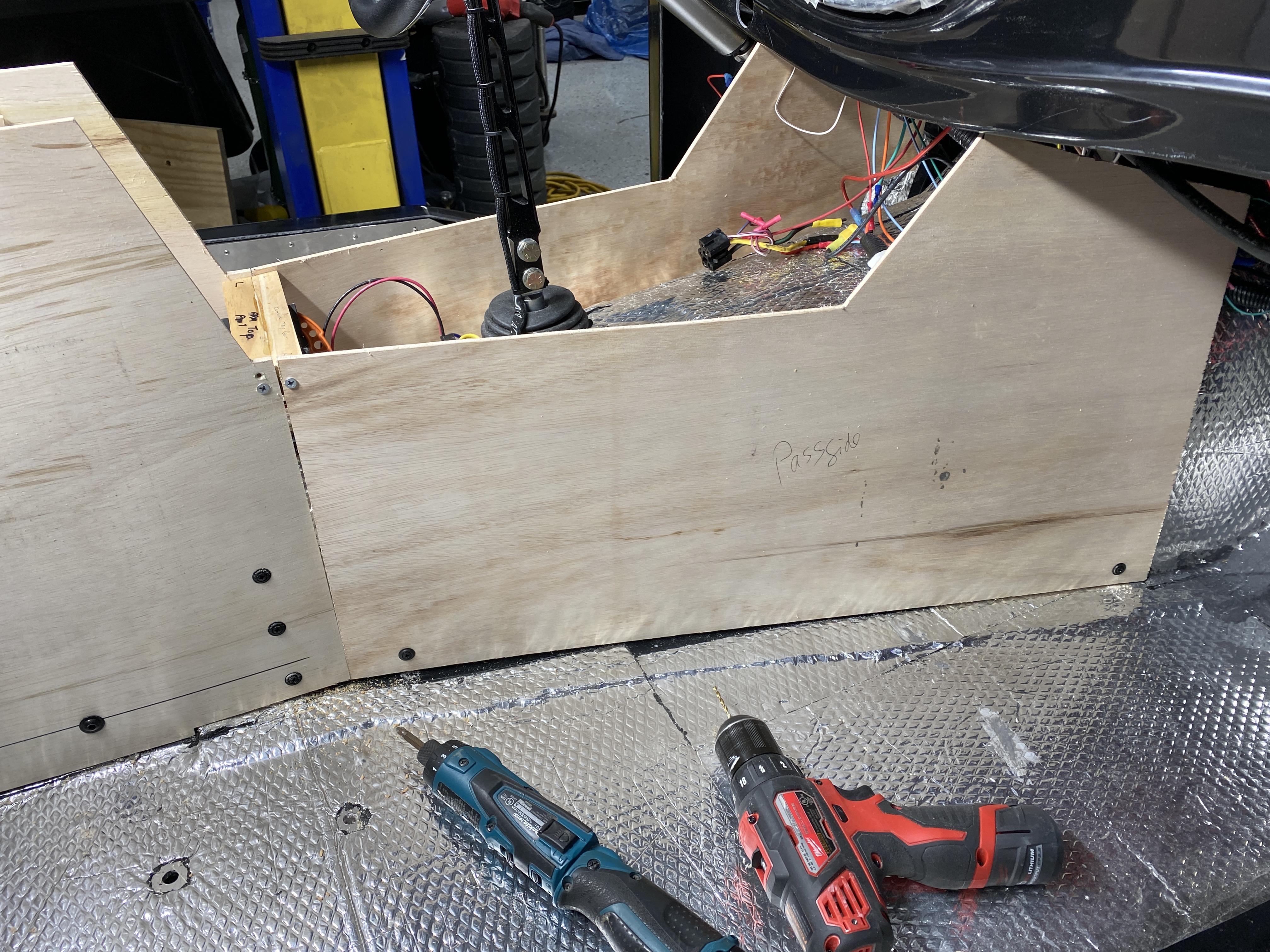
Finally, the last two pictures show all the bracing being glued in to support the tops and ends of the console.
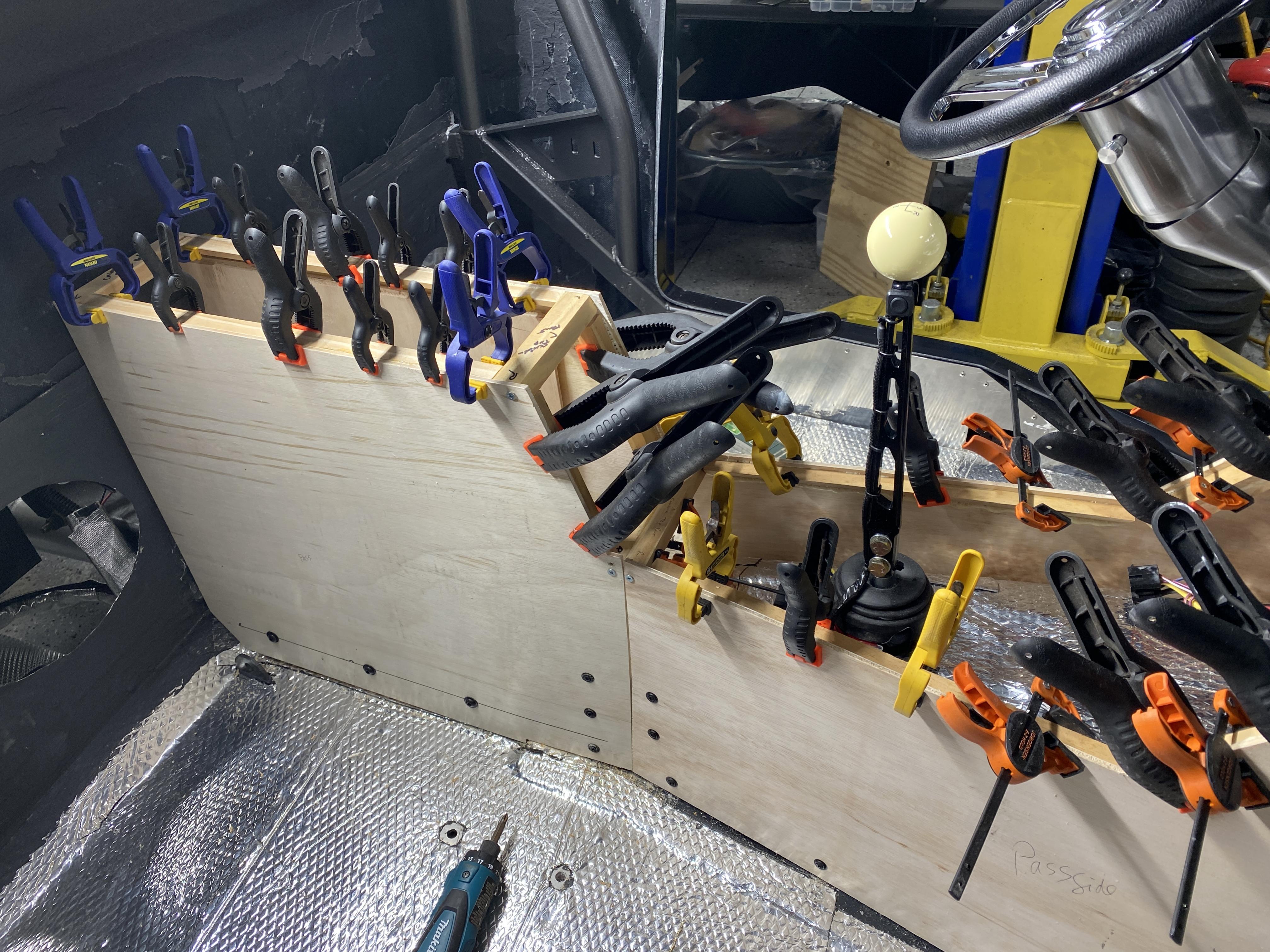
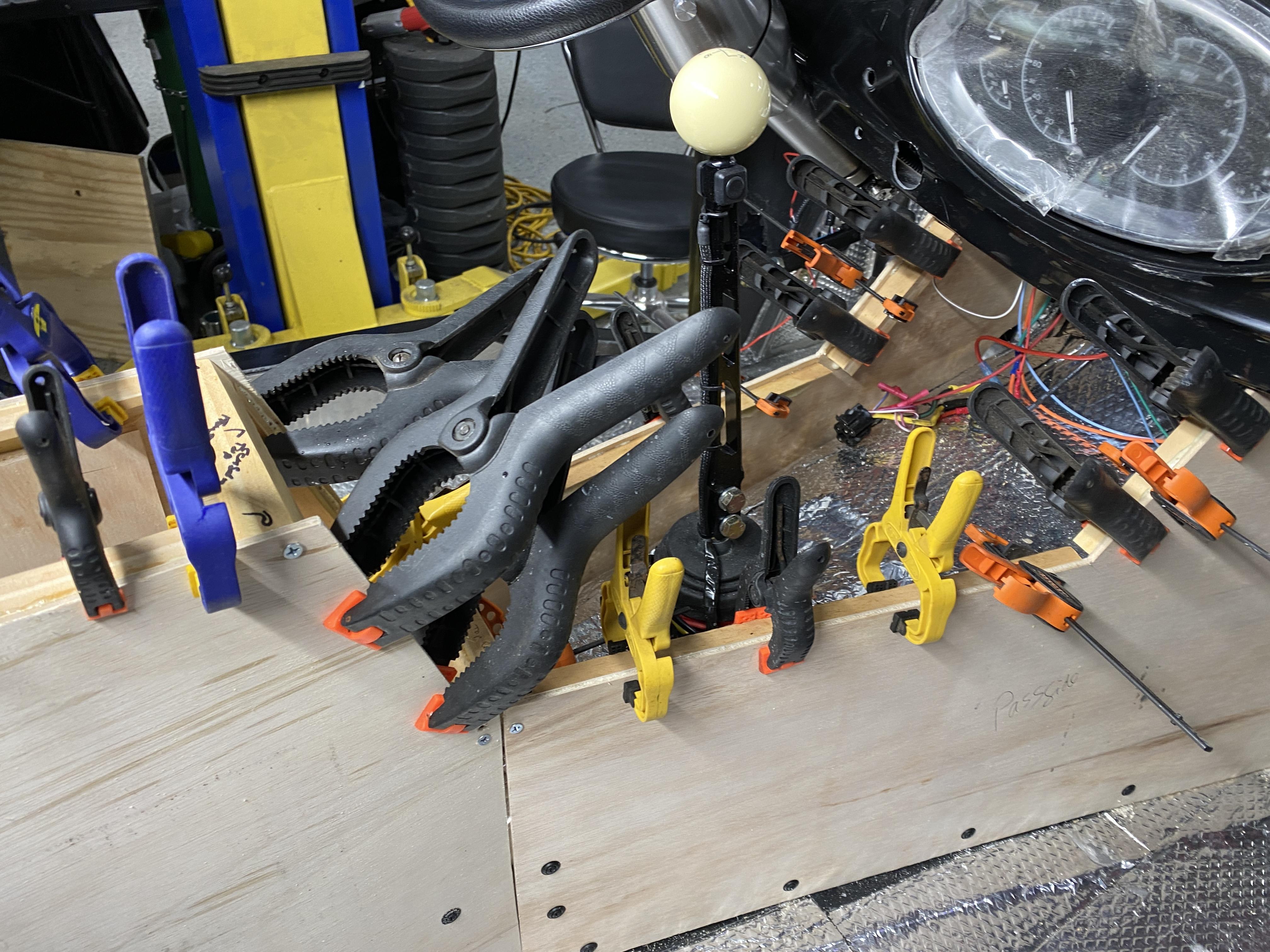
Today, I'll clean up the glue that squeezed out and make the tops. I'll also be cutting out the various panels where I'll mount the switches, buttons, stereo head, HVAC control panel, cup holder, etc. Also, I'll be completing the overhead console with wiring and simulated leather covering.
I'll update further tomorrow.
Mark
-
Post Thanks / Like - 0 Thanks, 1 Likes
-
08-01-2023, 04:04 AM
#164
Senior Member

Overhead Console Completed
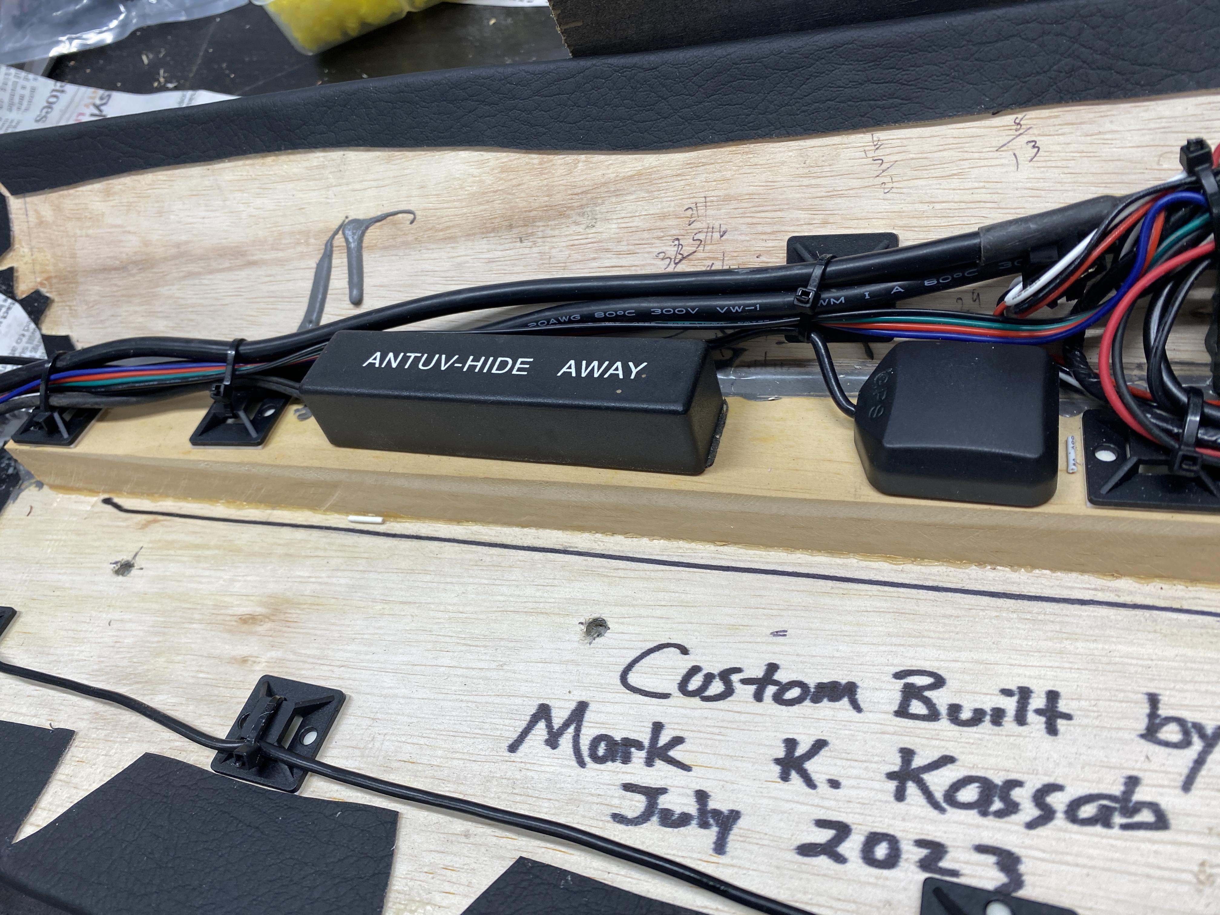
Here's the finished Overhead Console. It houses the HomeLink Garage Door opener, AM/FM hideaway antenna, the GPS antenna, the gauge dimmer, the clock set button, the Mic for hand free, the wiring for a Garmin Dashcam, 3 gauges (oil temp, fuel psi & vac) and a center mounted clock. I added quick disconnect male/female adapters for easy mounting and dismounting of the console and all wires run down the A-Pillar. For the actual mounting, I drilled and tapped into the roll bar. It's very solid piece.
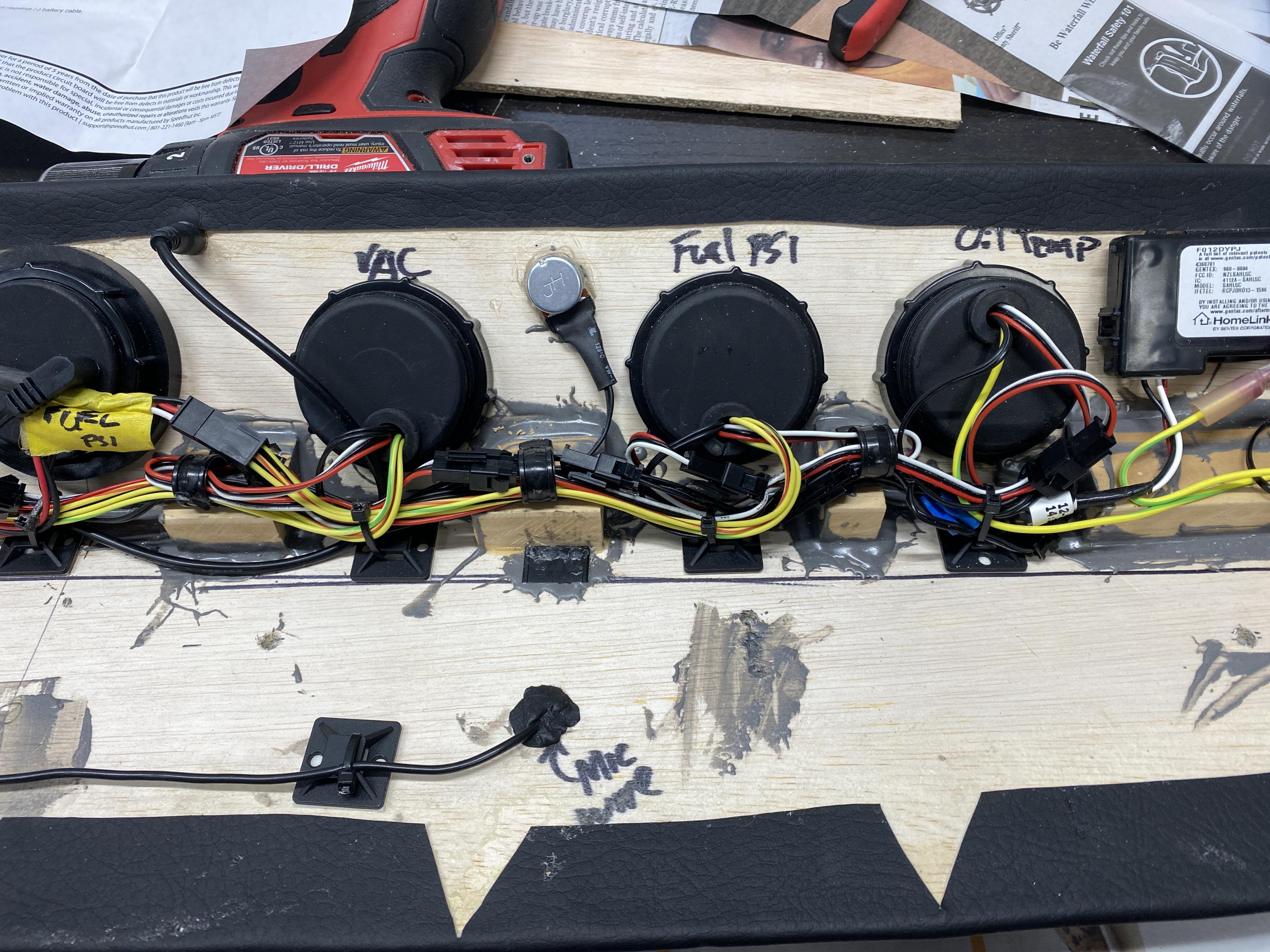
And the back side. You'll notice I added additional JBWeld epoxy over all the seams/joints for added strength.... a bit messy, but a very strong and secure structure. I ran a 4-wire "ribbon" cable from the dash and up to the console as a master supply for the 1) Batt constant 12v hot, 2) Ignition hot, 3) dash/park light hot and 4) a ground wire. This feeds all the gauges, clock, dimmer and the HomeLink unit.
The Floor Center console is coming along fine..... all the wood panels are cut. Today, I'll cut out all the various panels for the Stereo head, HVAC controller, window switches, USB ports, E-Stopp set button, and other misc items..... I'll post all that tomorrow.
Mark
-
Post Thanks / Like - 0 Thanks, 1 Likes
-
08-01-2023, 02:46 PM
#165
Damn buddy, this stuff is looking very good. I need to make some time to come visit before you're all done.
-
Post Thanks / Like - 1 Thanks, 0 Likes
-
08-01-2023, 06:04 PM
#166
Senior Member


Originally Posted by
Prslegmaker

Damn buddy, this stuff is looking very good. I need to make some time to come visit before you're all done.
Thanks Ronnie.... wait until you see the center console. It's coming out pretty good.... if I say so myself.
Mark
-
08-02-2023, 06:09 AM
#167
Senior Member

Center Console Construction with cutouts
Quick update on the center console build. I have only the top lid arm rest with hinges to complete before I start to cover with the vinyl. I also need to wire everything with quick disconnects and add the false bottom to the storage compartment before I take apart to cover.
As you'll see in the pictures below, I have the Stereo head unit and HVAC controller cutout and mounted for fitting. I'll add hold down screws (i.e., black oval head/washers) for all the panels. I need to figure out a way to support the weight of the rear part of the stereo head unit. The cup holder I finally went with (from Amazon) is a replacement cup holder for a GM truck.
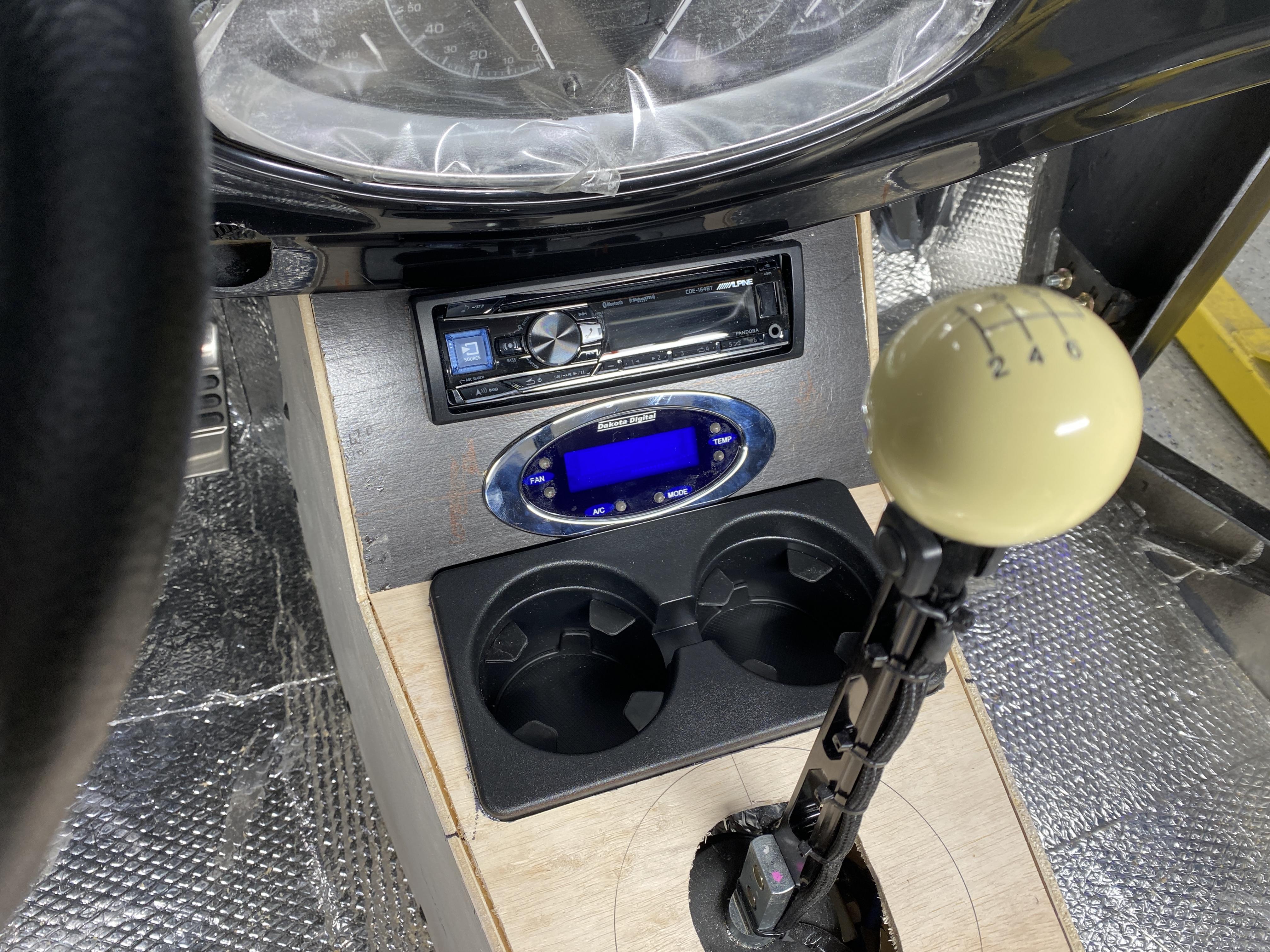
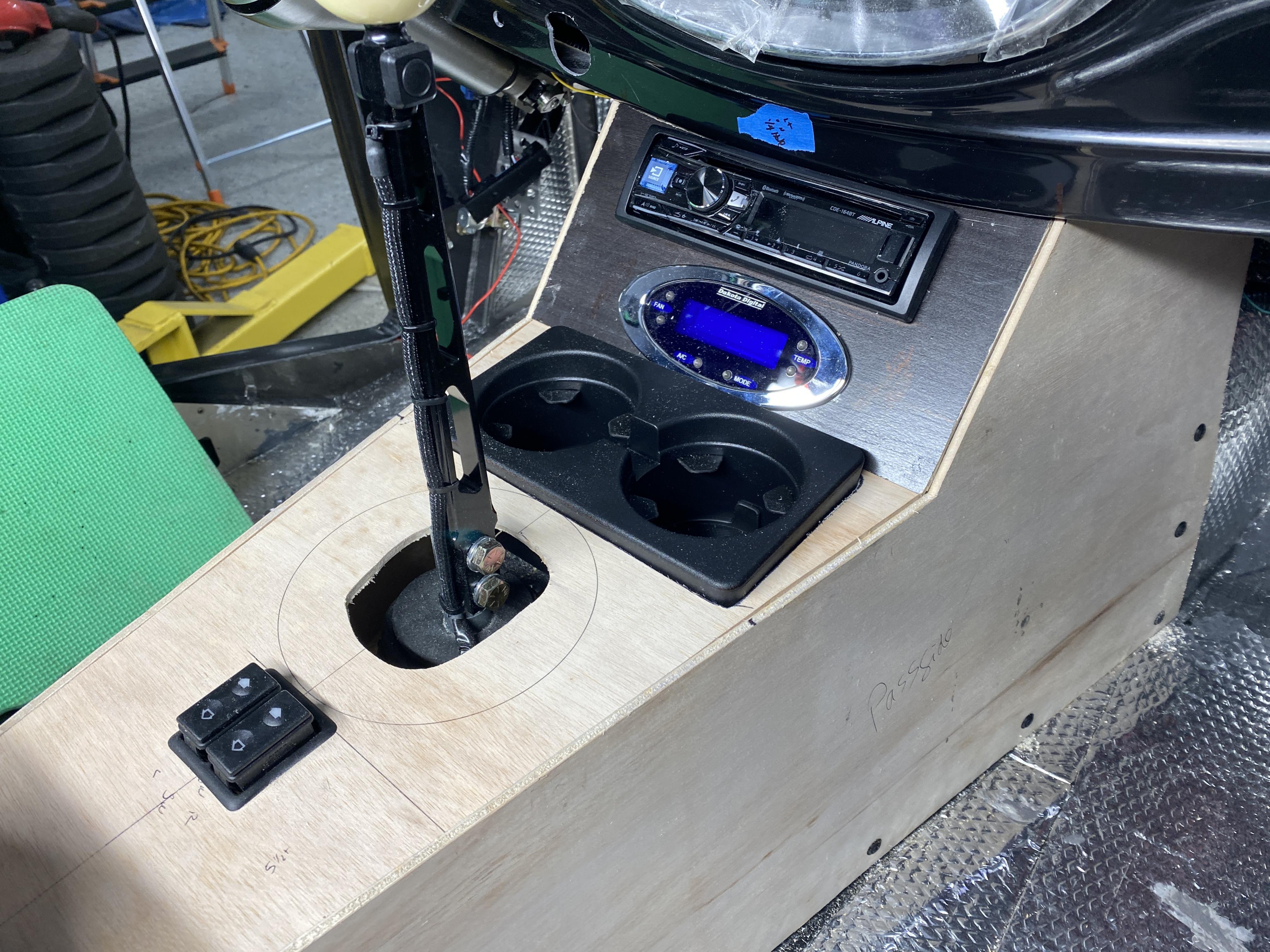
From this angle, you can also see the electric window switches ready for mounting just behind the stick shifter. Also note the blue painters tape above the stereo head unit on the dash. I'll mount a LED map light here, like the one I mounted on the arm rest rear panel you'll see in the next picture.
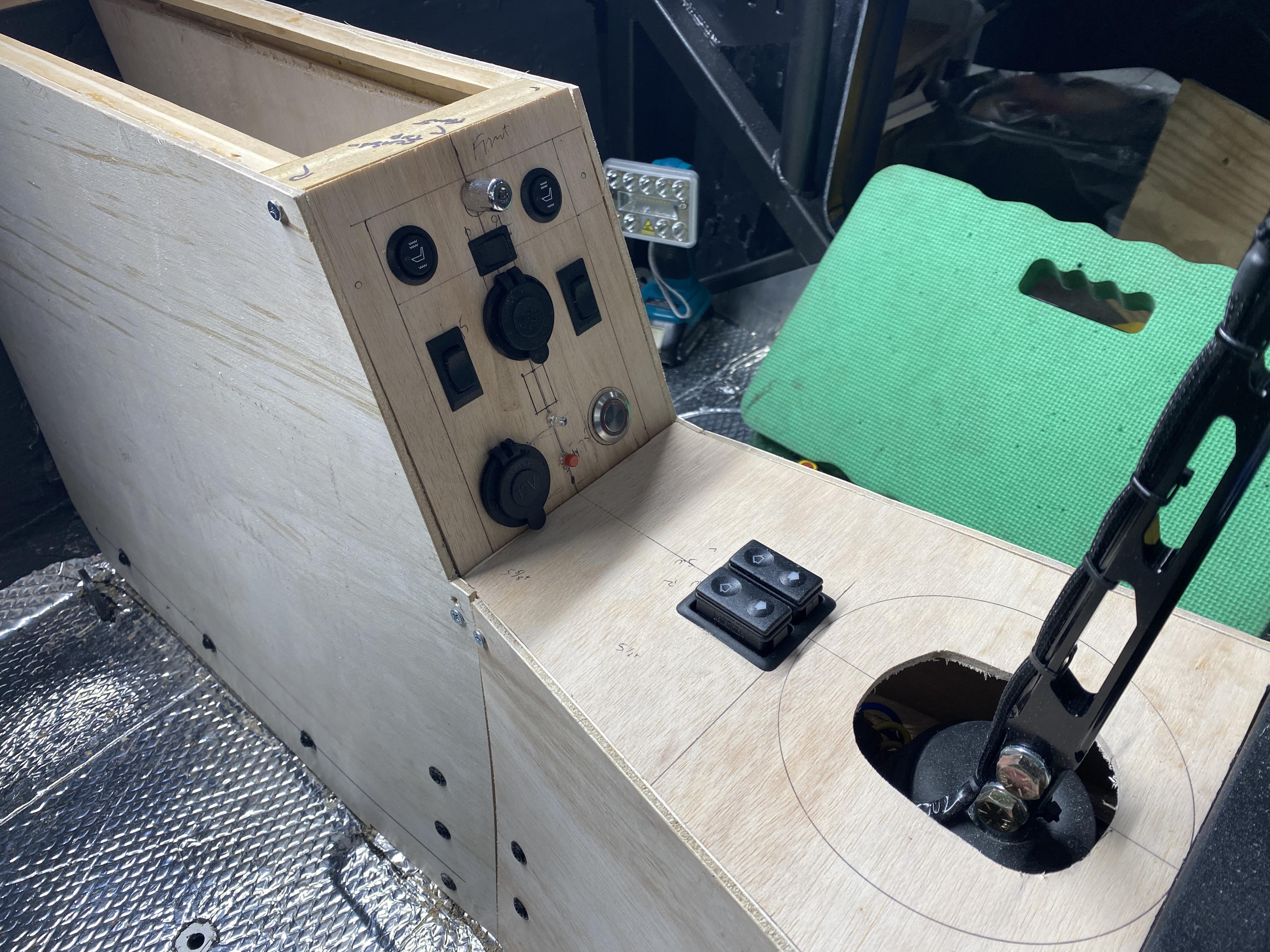
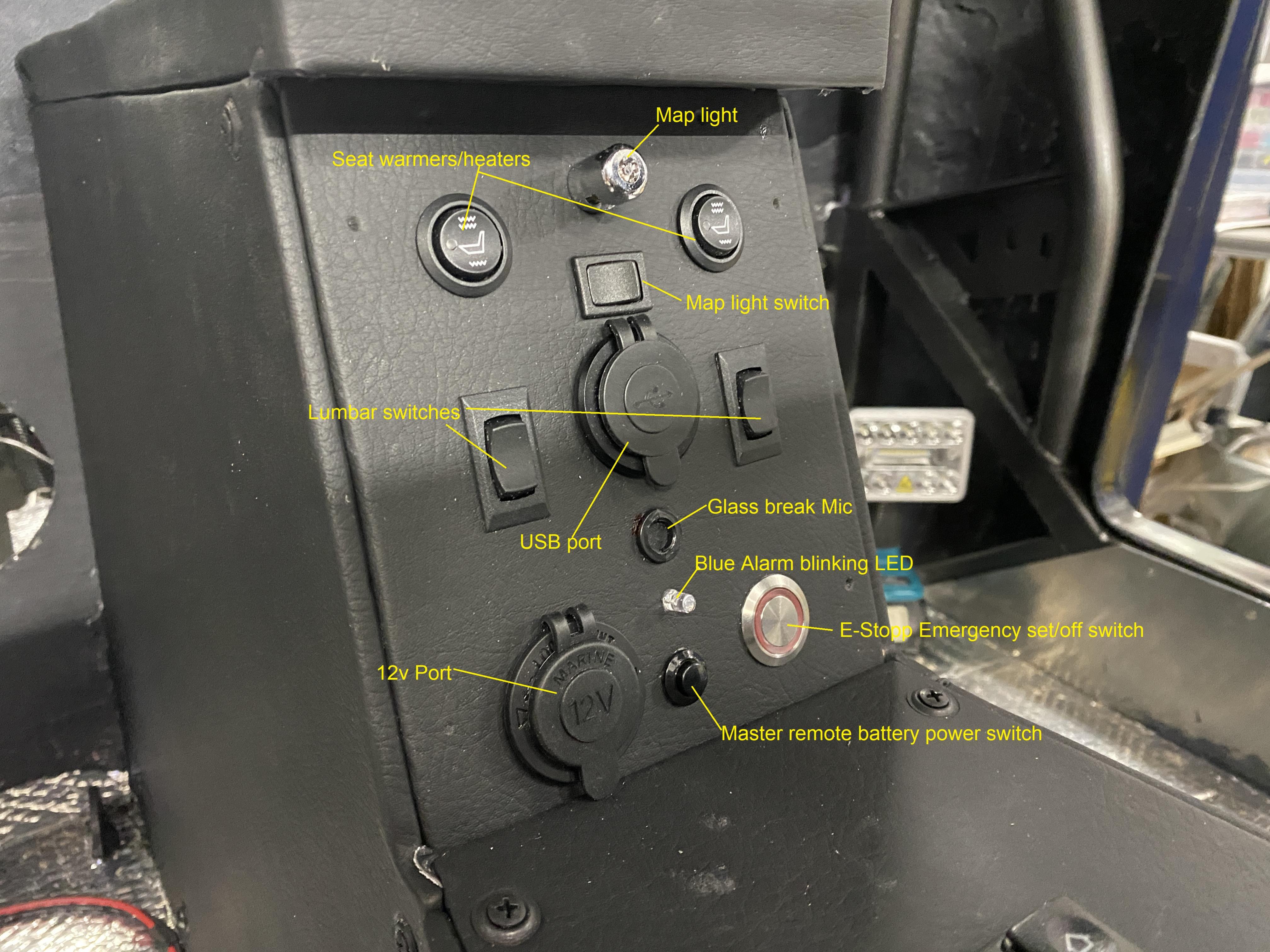
Lastly, the rear arm rest panel.... with Seat heater switches, lumbar switches, USB charger, map light, map light switch, blinking blue LED for the security system, 12v (cig lighter style) socket, E-Stopp set switch and the master 12v power switch on/off button.
Today, I'll focus on all the wiring in/under the console, the security system, etc.
Thx, Mark
Last edited by mkassab; 08-02-2023 at 06:15 AM.
-
Post Thanks / Like - 0 Thanks, 1 Likes
-
08-04-2023, 04:46 AM
#168
Senior Member

Console covering prep
Today is the day for the center console to be covered....
I've had a few requests to show more details of some of my little projects.... more of the "how to" building blocks.
I thought I'd share a few very basic pictures of the prep with the pattern cuttings/layout. I use the 3M High Strength 90 spray contract cement.
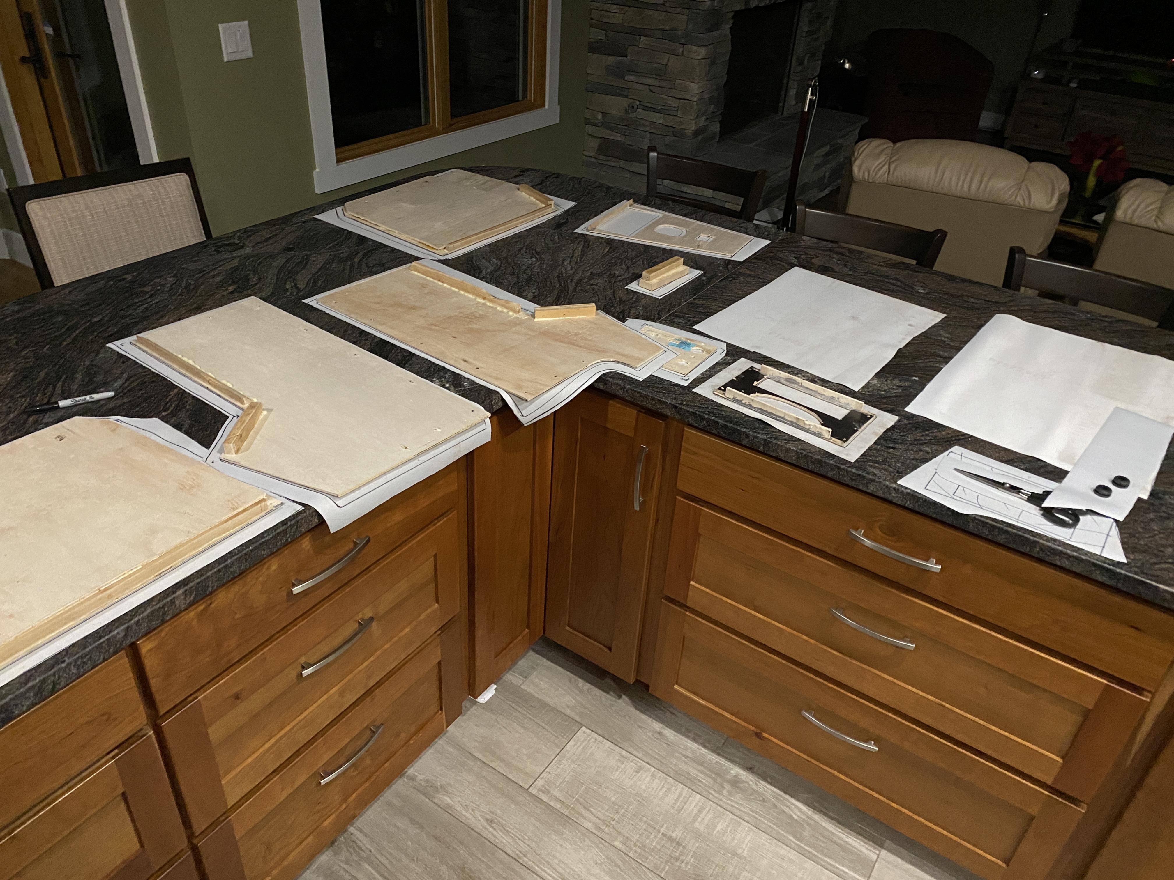
Here's a closeup of a few of the panels.
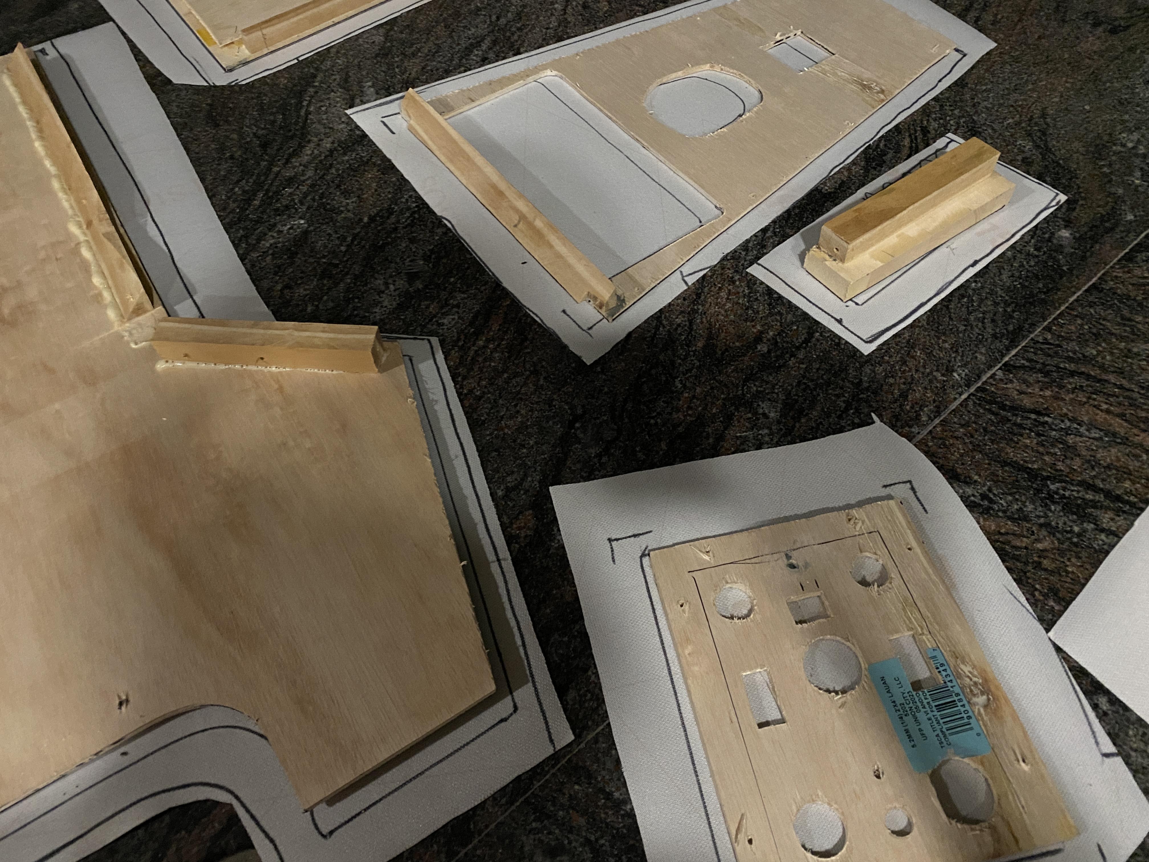
Yesterday, I wired up the security system and now that the console is removed from the cab, I can now clean up the wire "mess" and wrap and zip-tie to make it all clean and neat......!
I'll share the finished console pics tomorrow.
Thx Mark
-
08-06-2023, 05:41 AM
#169
Senior Member

Center Console complete
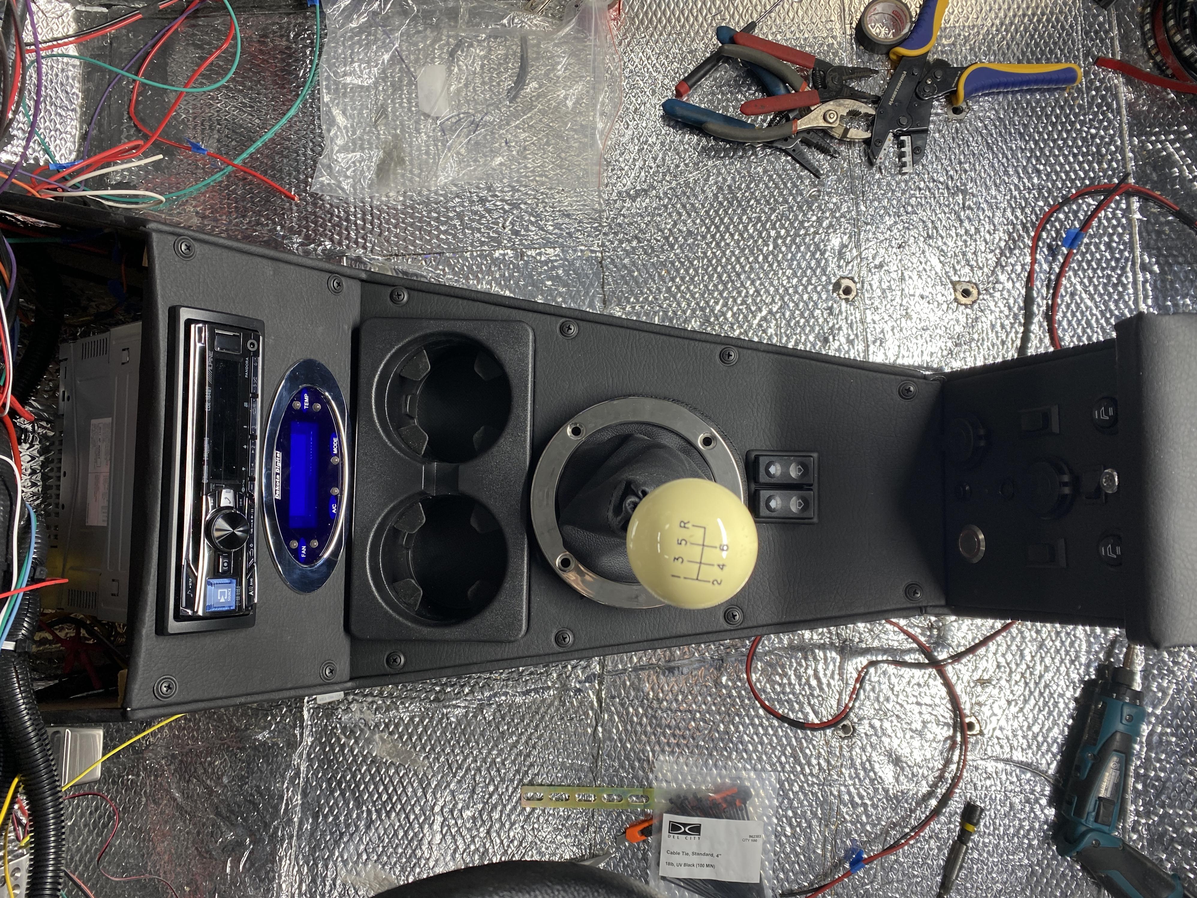
OK, here's the finished product.... center console. Please don't judge me too harshly on my console build results... as I'm sure not a professional upholsterer. All the pictures show a lot of dust/smudges and the camera highlights all of them and I didn't set/screw down all the panels. This was just a quick test fit. Obviously, the final installation will be much neater and clean!
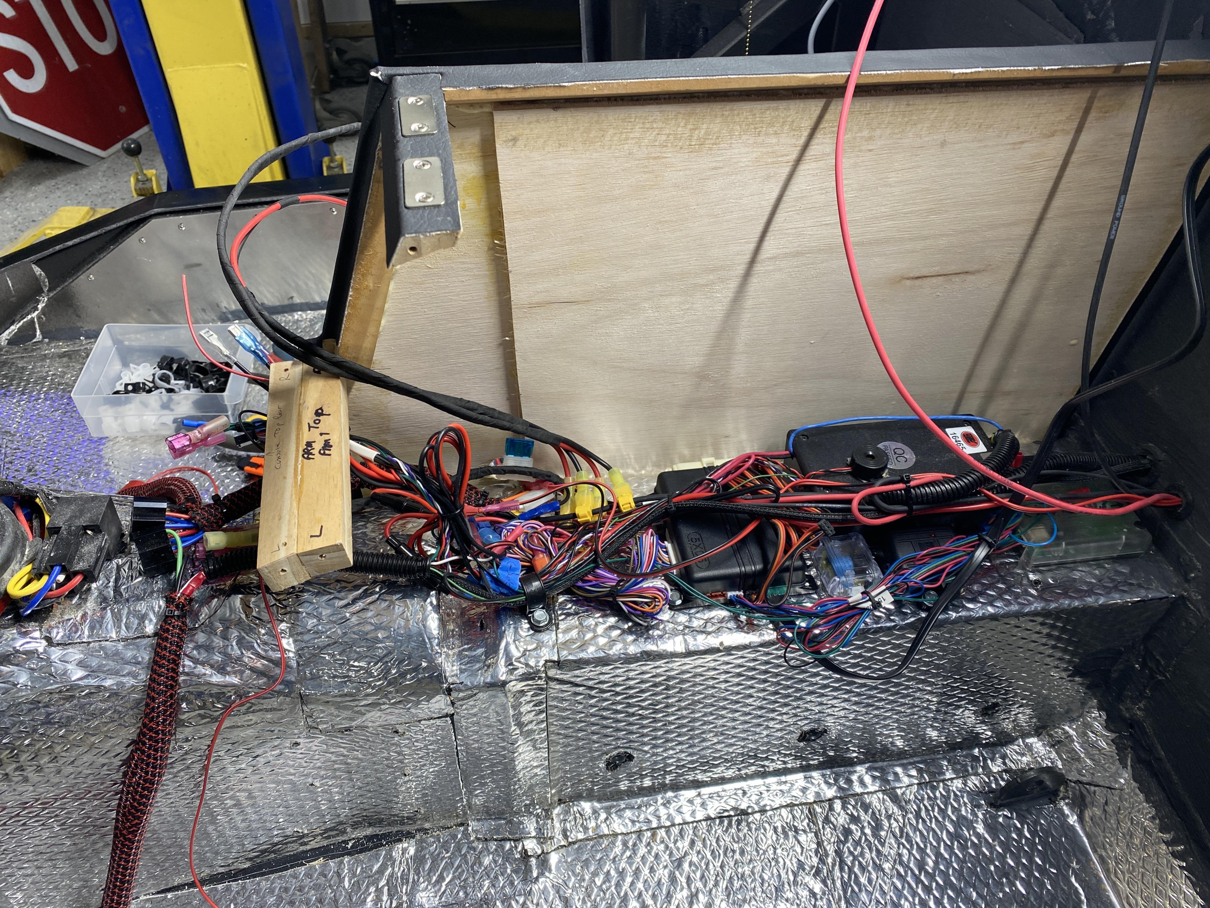
The first picture shows one side up and all the security alarm devices attached to the driveshaft tunnel. In addition, the E-Stopp main control unit is also attached to the tunnel. Some of the alarm components are a motion sensor, tilt/bump sensor, glass break sensor, the alarms main controller and an alarm remote antenna. All the wires towards the front will connect to the console panel I'll show below. I still need to make the false bottom that will cover up the security and E-Stopp components. I'll also install a 12v battery backup in the console for the security system. The backup battery will be charged by the alternator along with the chassis battery.
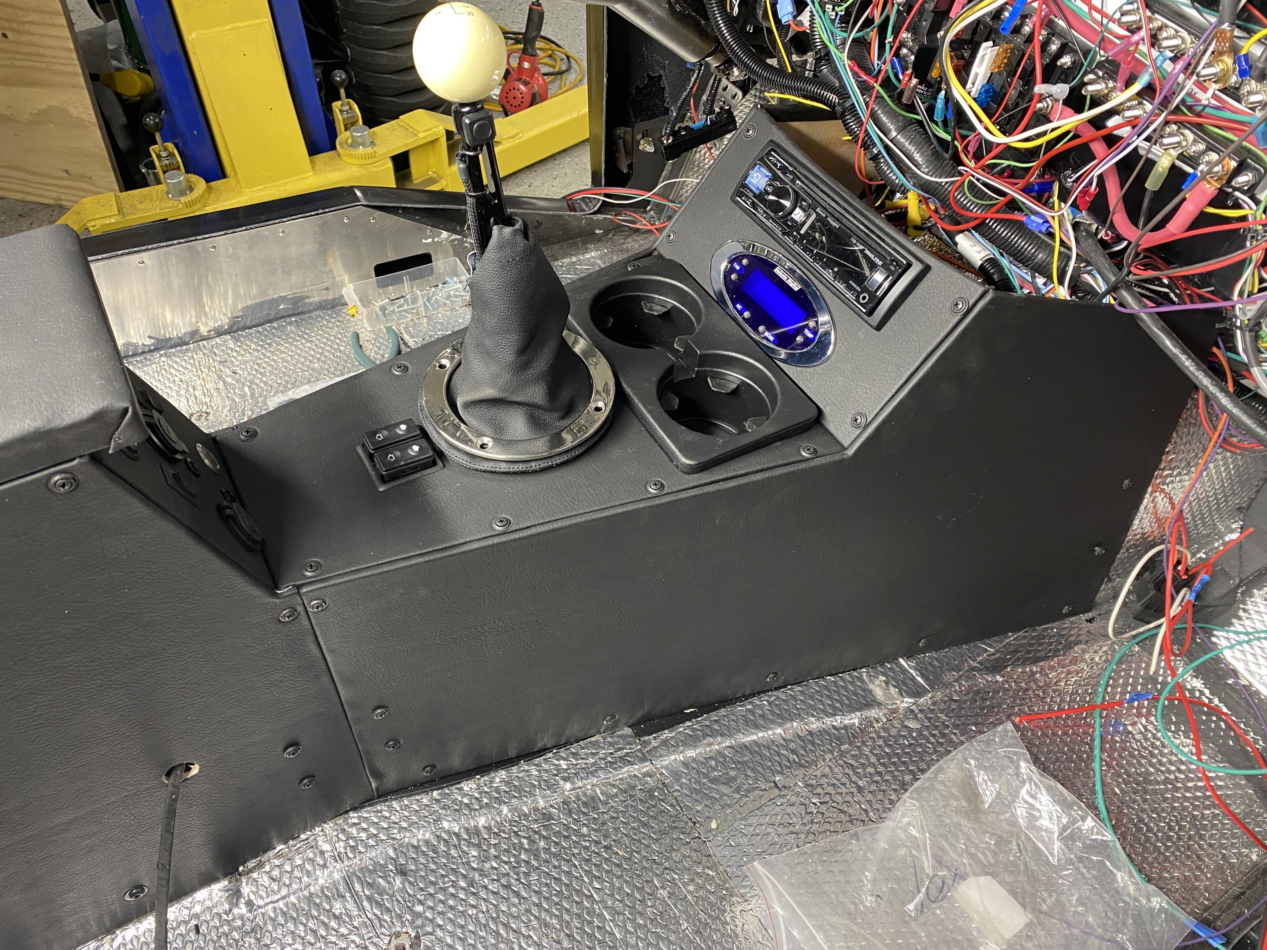
Here's a front side view. The wire coming out of the arm rest side is for the 12v power needed for the seat lumbar and heaters. The two switches behind the shifter are the door power window switches. Up front the stereo head unit and HVAC controller. The gear shifter boot is just sitting there for "placement" along with the GM cup holder that's a press-in fit.
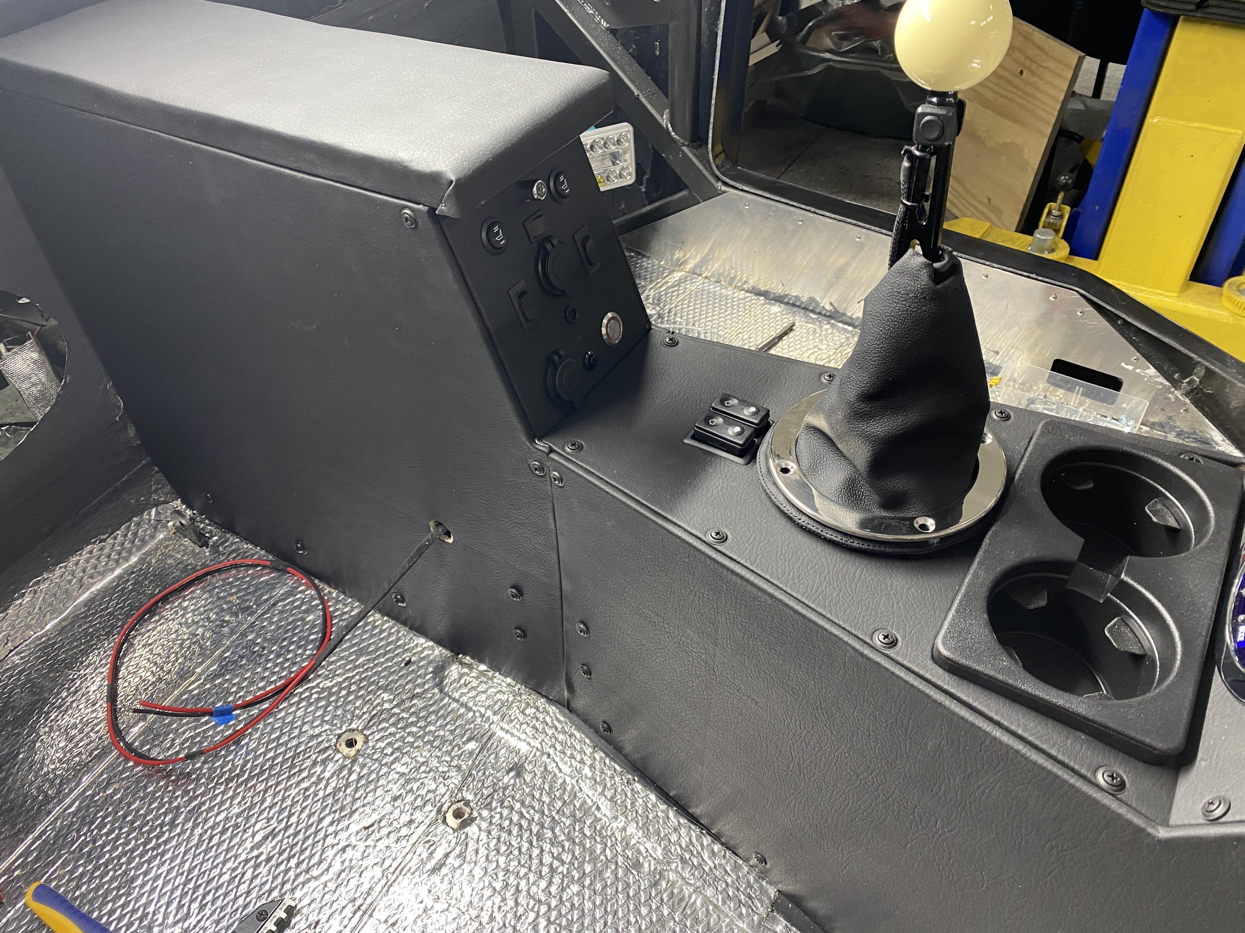
This angle shows more of the back half of the console. Once the seats are installed, it will help coverup all my console imperfections and help make them disappear.
Top down view
Lastly, a detail shot of the front arm rest panel and all its components labeled.
I still need to finish up the wiring on the stereo head unit, e.g., speakers, power, amp, etc. And I'll finish up the back of the dash wiring and quick disconnect connectors.
After that.... I'll start the door and other fiberglass panel fittings.
Mark
-
08-10-2023, 05:22 AM
#170
Senior Member

Wiper system installed
Not any picture worthy build items.... but I did get the windshield wipers fitted and installed. I mounted my wiper motor in the passenger side kick panel area like Paul did. Worked out well. I also decided to have my wipers oppose each outer for an "old timey" look... i.e., the wiper blades sweep from the center of of windshield, from the parked position, to the outside of the windshield. I also installed the upgraded wiper switch that has a 2 speed and intermittent (variable time) sweep and a windshield washer "push" switch built in.
Anyway, once all installed and tested, I dismantled and set aside until after paint and bodywork. I'll note that the wiper motor and blade transmissions were pretty quiet and I suspect once the engine is running, dash installed, carpet in and driving down the road with the stereo on it won't be that noticeable, if at all?
So, I'm now ready to tackle the doors and other body panel fitting.... not something I'm looking forward to, I think? Time will tell.
Mark
-
08-12-2023, 05:47 AM
#171
Senior Member

-
08-12-2023, 11:13 AM
#172
Senior Member

No reason you couldn't drill and tap those holes as you described. Although, as you said, the hinges hold the frame rigid once tightened down. I deviated from the instructions and bonded the frame in place pretty early in the process. Pretty risky move and not sure I'd recommend it. I was lucky I guess and it turned out OK. Getting the doors just right is a pretty big effort no matter what. Good luck. One hint: They have you tap one of the hinge holes because that particular mounting bolt is nearly inaccessible otherwise. Don't remember if it was the top or bottom. But I found that both top and bottom hinge halves are easier with one of the two holes tapped and not having to put a nut and washer on the other side. Don't remember if I mentioned that in my build thread. It's important because you'll have those hinges on/off and adjusting multiple times and they're not easy to access. It will be obvious which ones when you start working on them.
Build 1: Mk3 Roadster #5125. Sold 11/08/2014.
Build 2: Mk4 Roadster #7750. Sold 04/10/2017.
Build Thread
Build 3: Mk4 Roadster 20th Anniversary #8674. Sold 09/07/2020.
Build Thread and
Video.
Build 4: Gen 3 Type 65 Coupe #59. Gen 3 Coyote. Legal 03/04/2020.
Build Thread and
Video
Build 5: 35 Hot Rod Truck #138. LS3 and 4L65E auto. Rcvd 01/05/2021. Legal 04/20/2023.
Build Thread. Sold 11/9/2023.
-
08-12-2023, 11:58 AM
#173
Senior Member


Originally Posted by
edwardb

No reason you couldn't drill and tap those holes as you described. Although, as you said, the hinges hold the frame rigid once tightened down. I deviated from the instructions and bonded the frame in place pretty early in the process. Pretty risky move and not sure I'd recommend it. I was lucky I guess and it turned out OK. Getting the doors just right is a pretty big effort no matter what. Good luck. One hint: They have you tap one of the hinge holes because that particular mounting bolt is nearly inaccessible otherwise. Don't remember if it was the top or bottom. But I found that both top and bottom hinge halves are easier with one of the two holes tapped and not having to put a nut and washer on the other side. Don't remember if I mentioned that in my build thread. It's important because you'll have those hinges on/off and adjusting multiple times and they're not easy to access. It will be obvious which ones when you start working on them.
Thanks Paul.... As far as bonding.... here's what I'm thinking. After I drill/tap the interior bracing. I was thinking of putting plastic cling wrap on the end of the metal bracing (i.e., the part of the bracing that butts up against the front and rear part of the door) the then applying the 3M 46014 Marine High Strength Repair Filler to the door and brace.... then reattach the bracing into the door which will cause the filler to fill in all gaps between the door and bracing... bond to the door, but the bracing will release from the filler because of the plastic wrap. That way, I'll have a good flat surface for when it's installed, but with the bracing still being removable. Any thoughts on that?
Thx again, Mark
-
08-12-2023, 02:12 PM
#174
Senior Member


Originally Posted by
mkassab

Thanks Paul.... As far as bonding.... here's what I'm thinking. After I drill/tap the interior bracing. I was thinking of putting plastic cling wrap on the end of the metal bracing (i.e., the part of the bracing that butts up against the front and rear part of the door) the then applying the 3M 46014 Marine High Strength Repair Filler to the door and brace.... then reattach the bracing into the door which will cause the filler to fill in all gaps between the door and bracing... bond to the door, but the bracing will release from the filler because of the plastic wrap. That way, I'll have a good flat surface for when it's installed, but with the bracing still being removable. Any thoughts on that?
Thx again, Mark
Personally not sure of the advantage of having it removable once you lock in the location with the HSRF. Might be hard to get in/out just because of how it fits. Even with the plastic wrap. But that's just my first reaction and maybe you've thought about it more. No one way to do these things.
Build 1: Mk3 Roadster #5125. Sold 11/08/2014.
Build 2: Mk4 Roadster #7750. Sold 04/10/2017.
Build Thread
Build 3: Mk4 Roadster 20th Anniversary #8674. Sold 09/07/2020.
Build Thread and
Video.
Build 4: Gen 3 Type 65 Coupe #59. Gen 3 Coyote. Legal 03/04/2020.
Build Thread and
Video
Build 5: 35 Hot Rod Truck #138. LS3 and 4L65E auto. Rcvd 01/05/2021. Legal 04/20/2023.
Build Thread. Sold 11/9/2023.
-
Post Thanks / Like - 1 Thanks, 0 Likes
-
08-13-2023, 05:59 AM
#175
Senior Member

Door fitting spacer stands... build tip
Another great "tool" I borrowed from Paul's (aka edwardb) build is the use of door fitting spacer stands. Here's what/how I "copied" the idea.
I had these two 3/16" thick steel angle braces. I took some scrap wood laying around, added a flat base to it and I simply clamped the angle braces to them to map to the height of the bottom of the door jambs. It worked great. Thanks Paul again for another great build tip.
BTW, the angle braces were from an old build.... they were from the seat belt floor anchors to bolt the seat belt to.
I wanted to share incase others weren't aware of this tip.
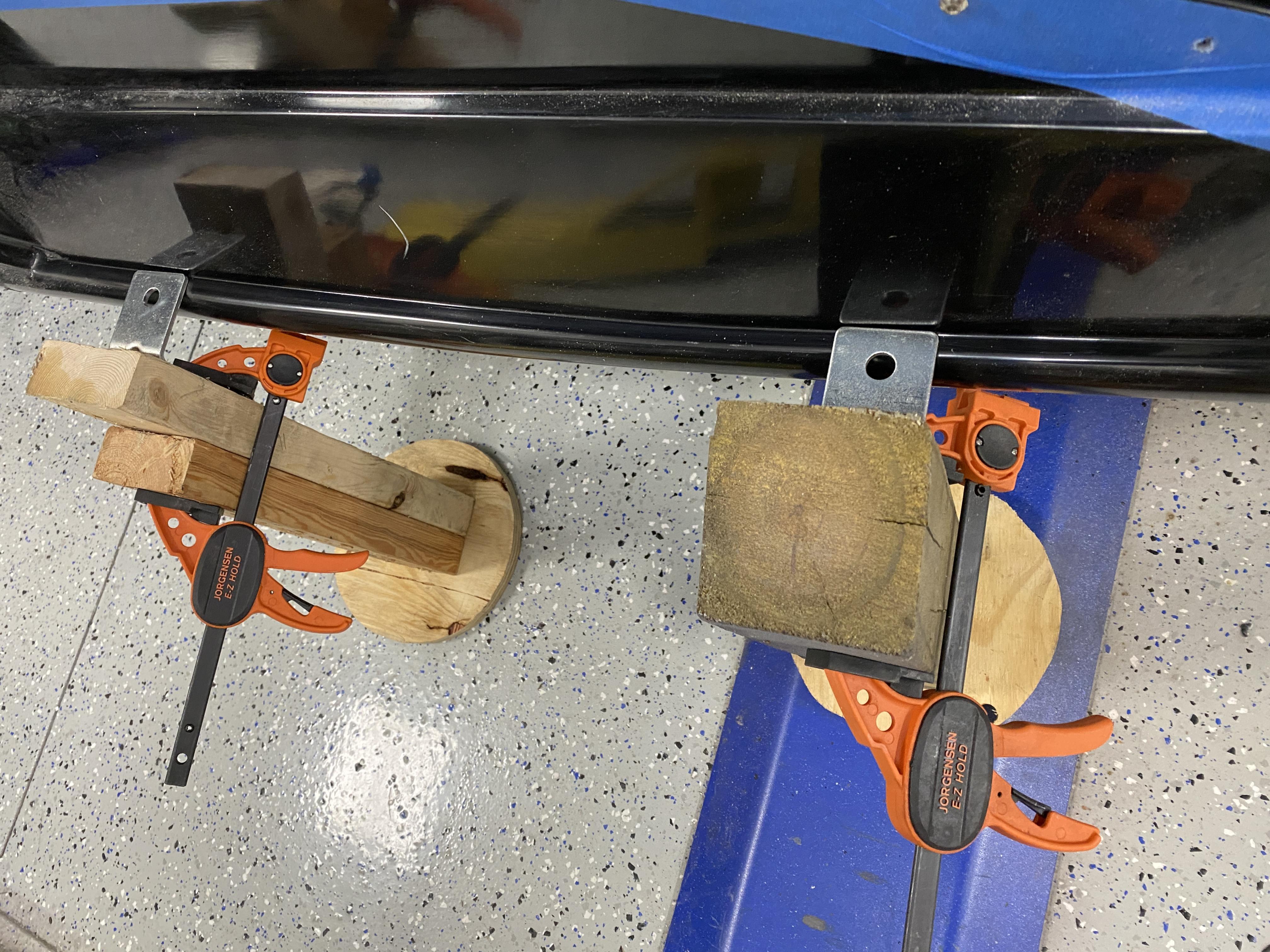
And this pic with the door in place sitting on the braces and duck taped at the top.
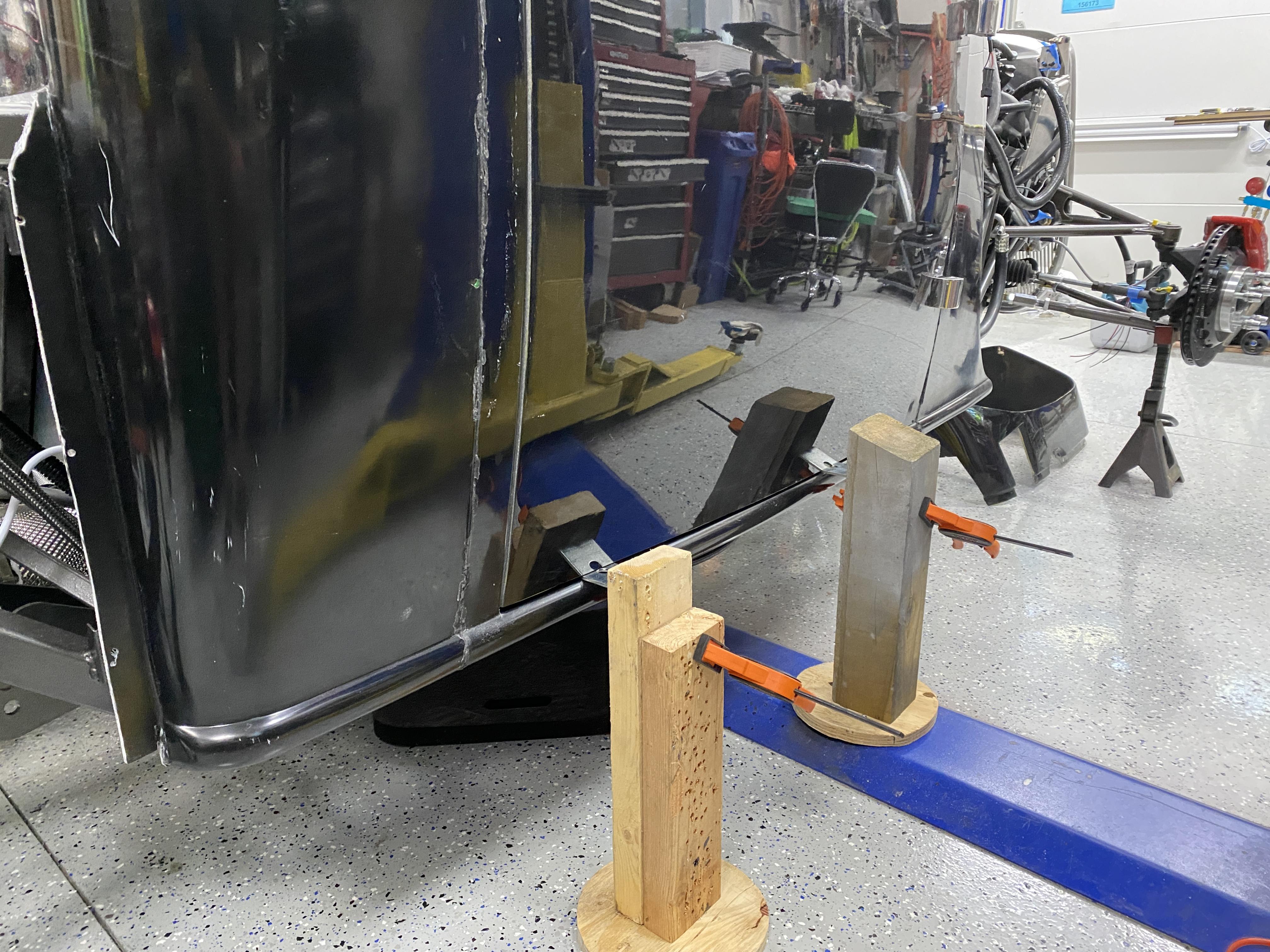
I hope this can help someone like it did me.
Mark
Last edited by mkassab; 08-13-2023 at 06:26 AM.
-
Post Thanks / Like - 1 Thanks, 1 Likes
-
08-14-2023, 06:33 AM
#176
Senior Member

-
08-15-2023, 06:44 AM
#177
Senior Member

Truck Bed Wood started... 1 of x
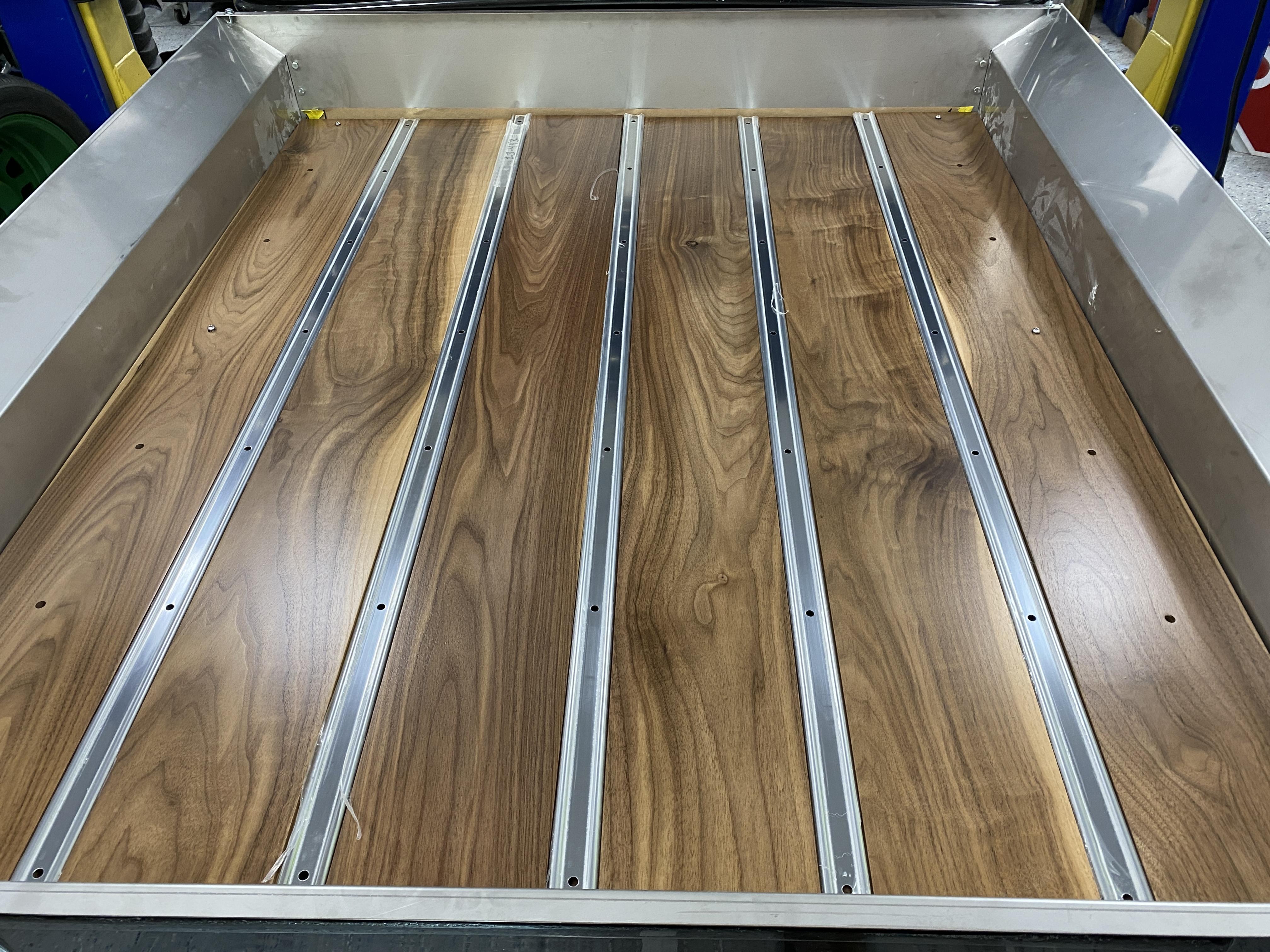
While waiting for cooler weather to do all my fiberglass sanding... I turned to the truck bed. As I stated in earlier posts in this thread, I intended to add a Black Walnut bed wood to lay over the FFR SS sheet metal. I want both the bed wood and ss sheet metal to be easily removal. So here's my start to being able to do just that. It will take several post to show it all... but here's the start. So this post is 1 of several.
First, I laid out the left to right cross rails that I'll attached the bed wood and ss between strips to. In this first pic, the wood is just laying on the cross rails with the ss strips not attached. I really think this Black Walnut will look and contrast well with the light pastel green I'll paint the truck.
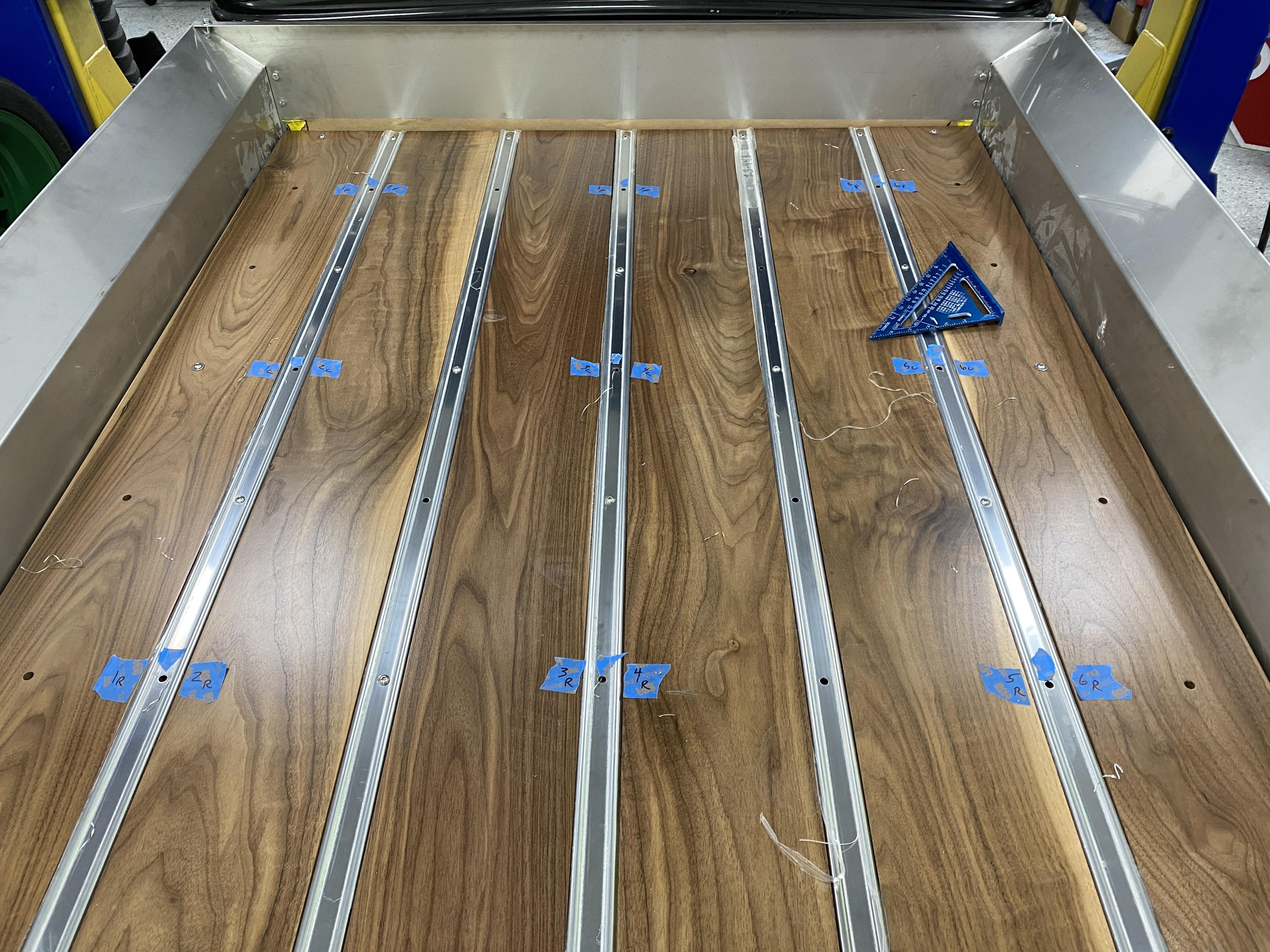
In the next pic below, you'll notice 9 ss strip mounting holes with blue painters tape. I'll drill through the cross rails below the then drill through the FFR SS sheet metal. Once I remove all the rails/wood, I'll install rivet nuts in the FFR SS sheet metal. This will be how I mount the bed wood assembly to the truck's bed. Once all mounted, all I'll have to do is remove these 9 ss 1/4"-20 pan head bolts to remove the entire bed wood assembly and thereby exposing the FFR ss sheet metal below it. In another post later, I'll show how I attached the FFR ss sheet metal to the truck frame. The SS sheet metal will also be easily removed for any service that might be needed to the systems under the sheet metal.
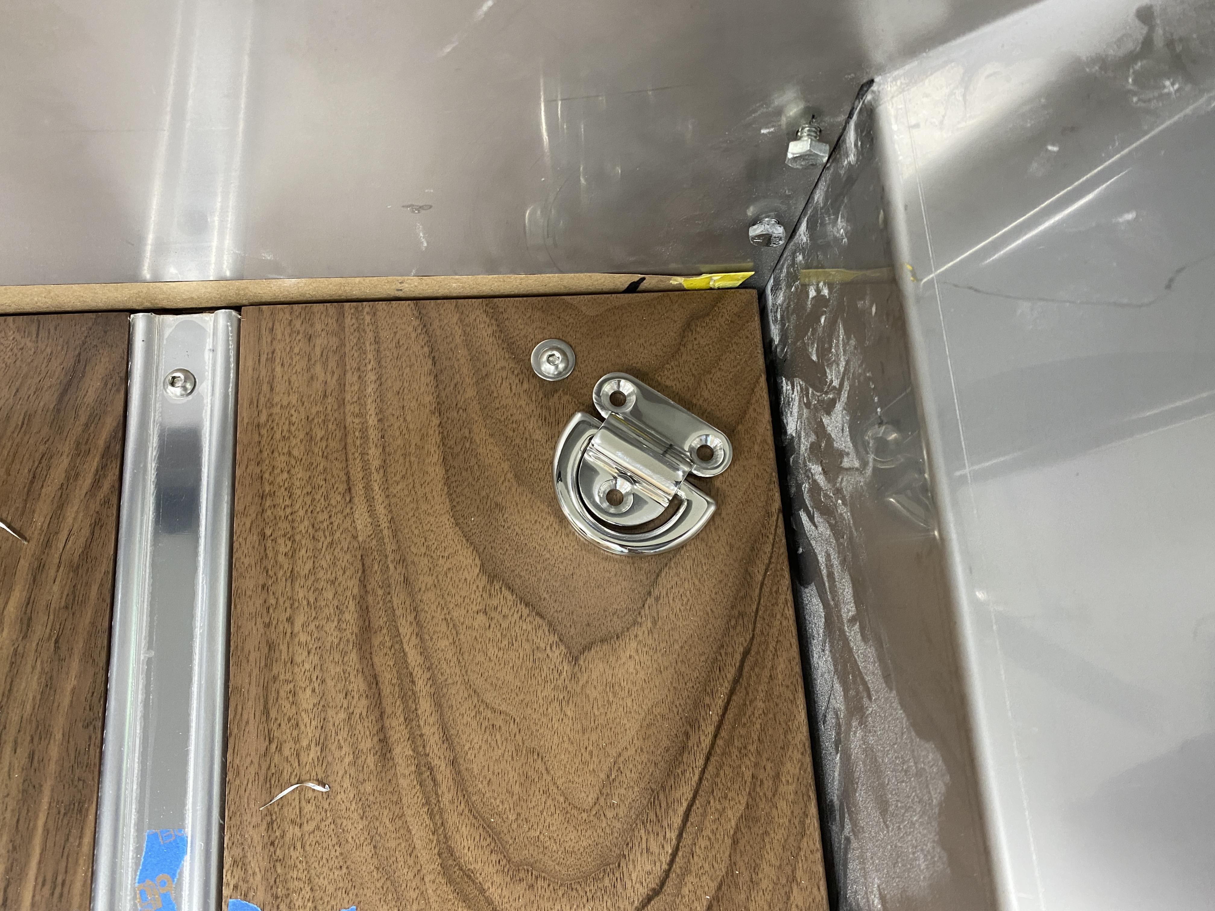
Lastly, I'll mount these marine grade lift fasteners to the wood in each of the four corners. They can be used to tie down any cargo AND/OR lift the bed wood assembly out of the truck's bed.
So, today, I'll continue the bed mounting installation I described above. You won't see the final product until after I paint the truck. My goal to paint the truck is later this fall when the temp and humidity are low and perfect conditions for me to paint.
Stay tuned,
Mark
-
08-16-2023, 06:53 AM
#178
Senior Member

Bed Wood install 2 of x
I wanted to share the base for the Bed Wood install.
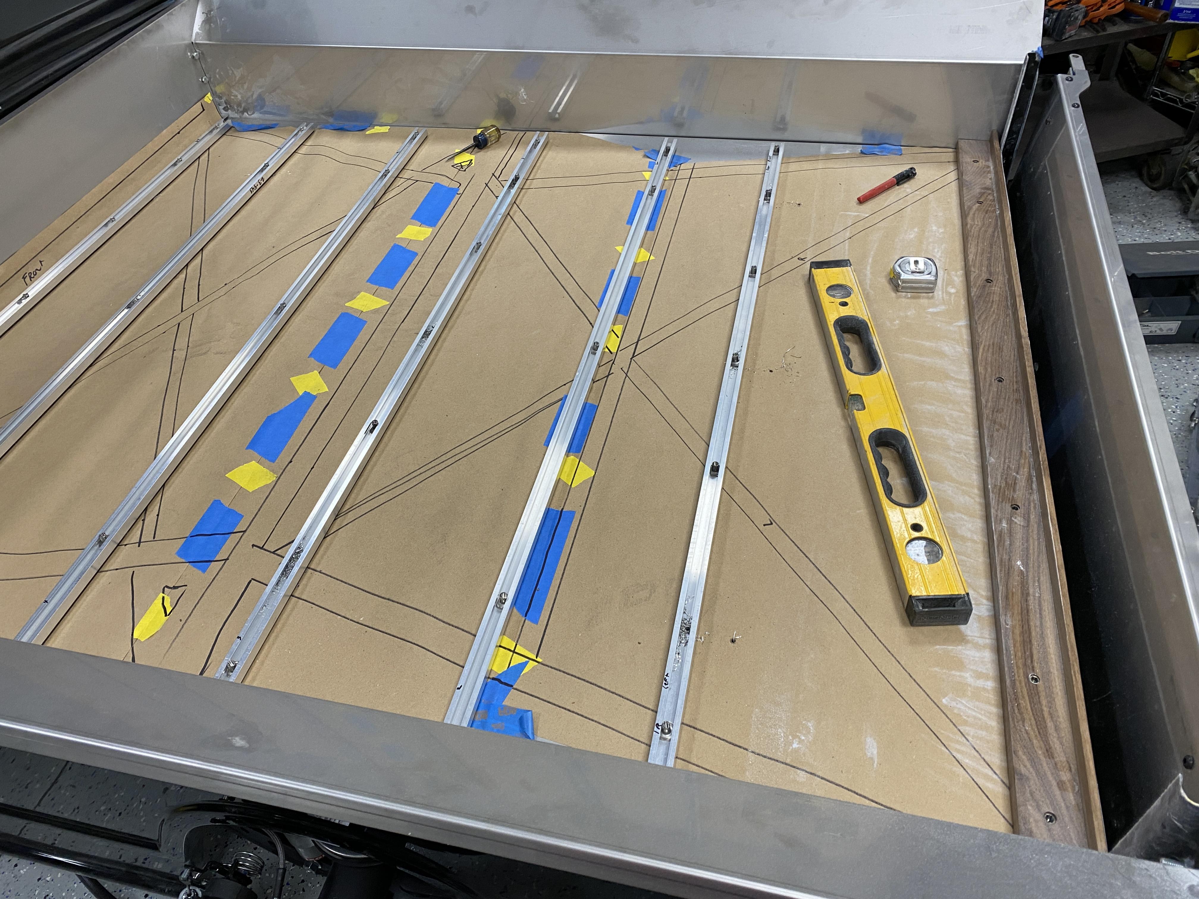
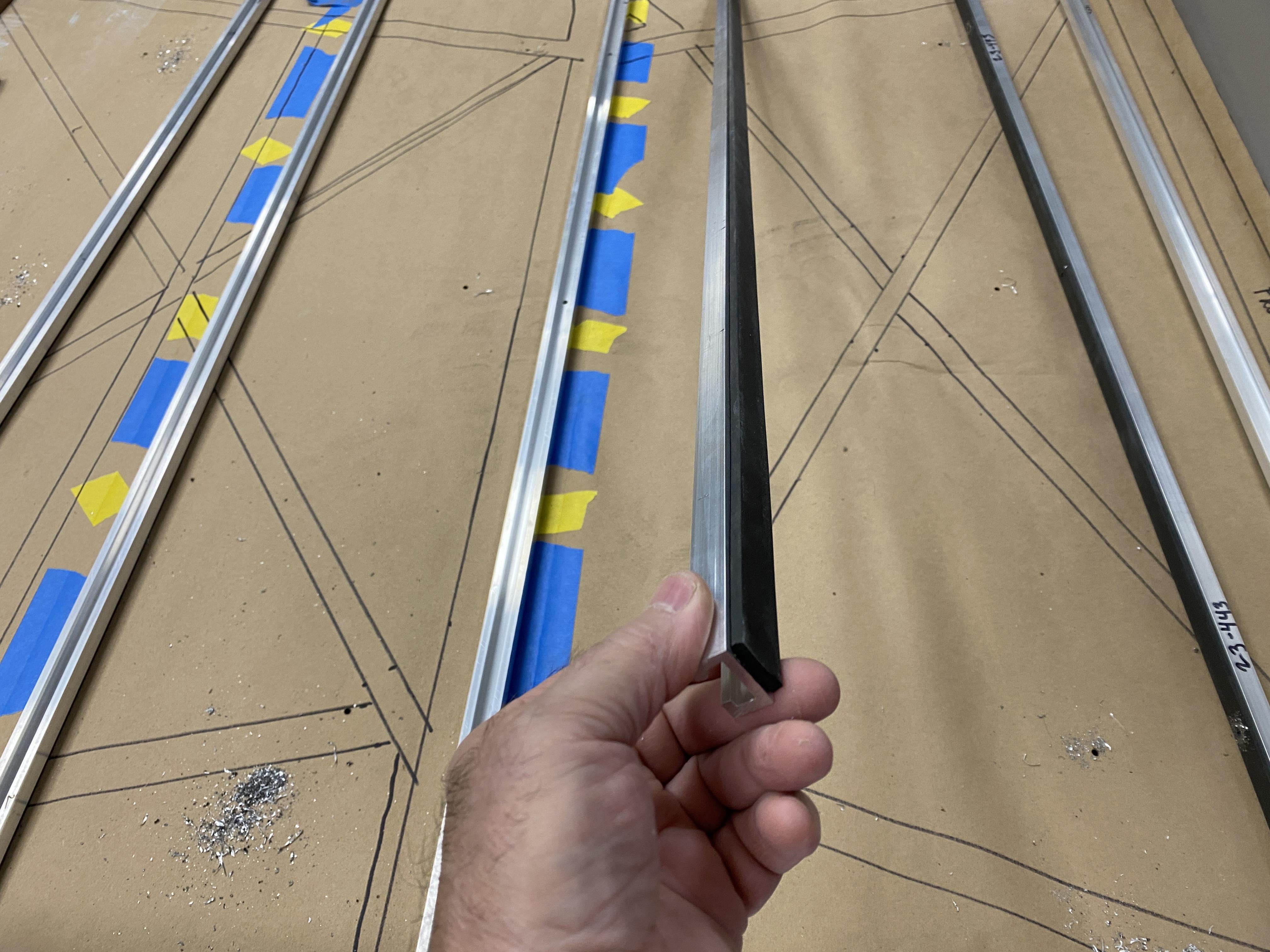
In the pic below, you'll see different items, i.e., 1) the paper template I made of the chassis frame under the FFR SS bed sheet, 2) the cross mount rails the bed wood will fasten to and 3) on the far right of the picture, the wood end cap for the bed wood planks/boards.
I'll use the paper template of the frame to determine where to drill and tap 9 mounting points to bolt down the SS sheet to the frame. I'll drill in the frame below, tap with a 1/4"-20 and bolt the ss sheet to the frame with SS button head bolts. Between the ss sheet and the frame, I'll add thin rubber strips to prevent and metal to metal contact and squeaks.
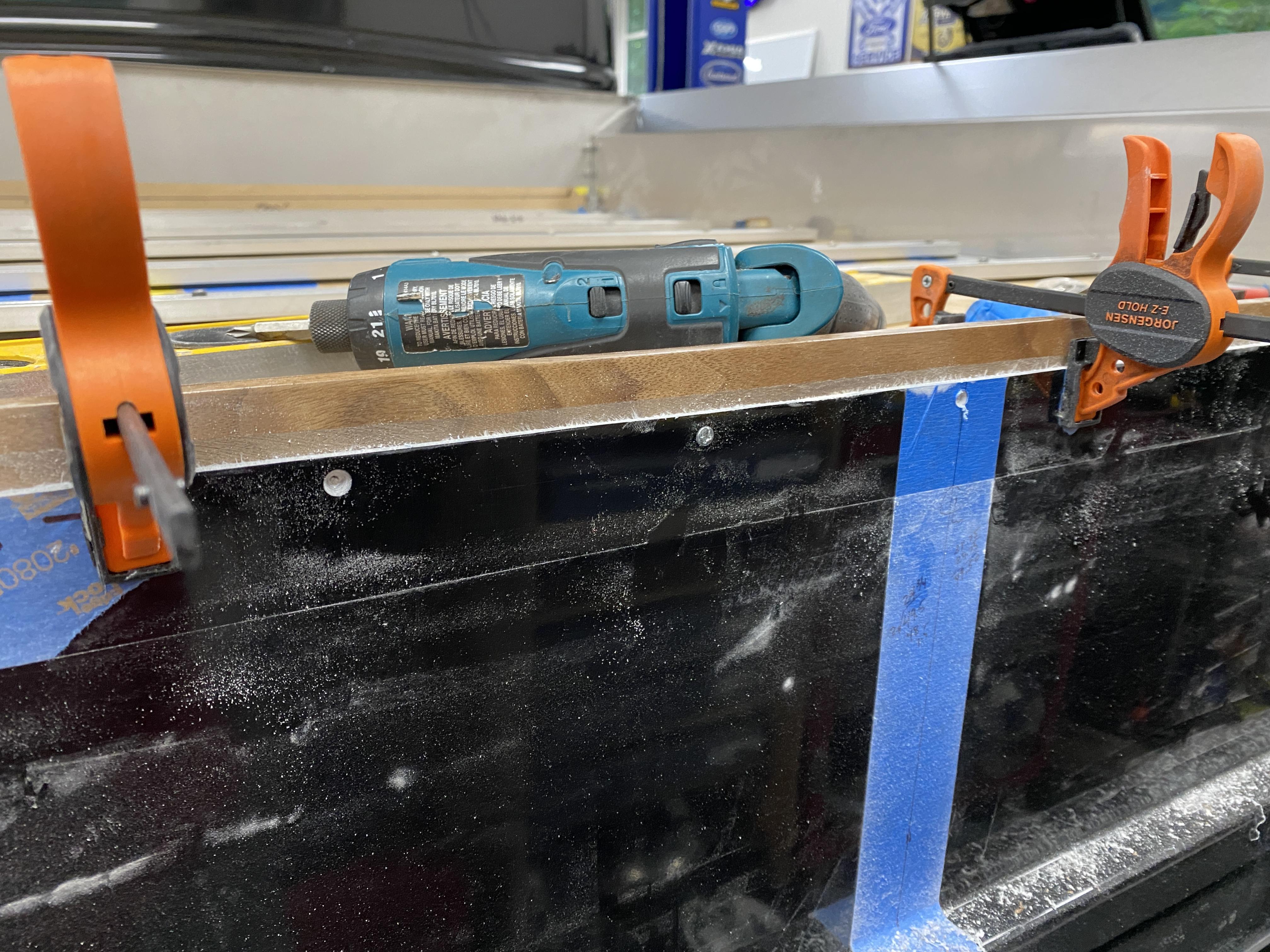
In the next pic, I show how I drilled and screwed the end fiberglass valance to the bed wood end cap. I'll add some sort of slip-on edge protector to the fiberglass.... something like door edge guards, to dress up the edge.
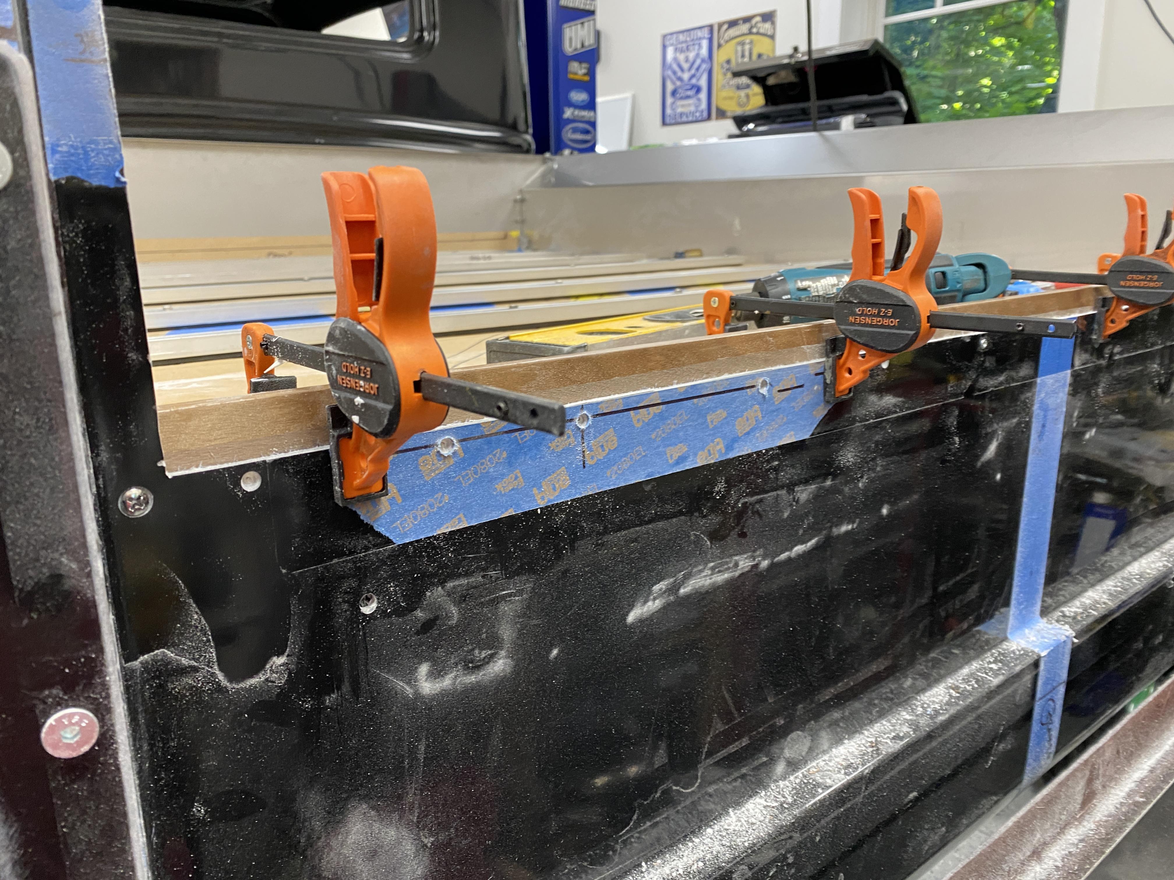
Closeup
Lastly, some cross mounting rails pics showing the rubber bottoms and the key slots in the rail to slide the T-Nuts in the rail to attached the bed wood ss strips. As I mentioned in the previous post, nine of the bedwood strip holes will not have T-bolts, i.e., in those 9 holes, I drilled through the cross mount rails, through the ss sheet and installed 1/4-20 rivet nuts. This will firmly hold down the bed wood assembly to the truck's bed.

Today, I'll work the bed side pocket mountings and the tailgate latches. I'll also be installing the backup camera and hitch receiver... more pics on all that soon.
Mark
-
08-16-2023, 01:29 PM
#179
Hi Mark, where did you get your backup camera? I haven't found one i like yet.
-
08-17-2023, 04:55 AM
#180
Senior Member

Backup Camera unit

Originally Posted by
Prslegmaker

Hi Mark, where did you get your backup camera? I haven't found one i like yet.
Ronnie... I bought my backup system from Rear View Safety. Great company and service. BTW, if military or vet, you'll get a 10% discount.
Here's the link to what I bought... https://www.rearviewsafety.com/safet...o-dimming.html
They have a vary large selection to choose from.
I bought the unit with the camera, mirror and it's auto dimming. I didn't get the one with temp or compass since my Dakota Digital instruments gives me the temp and compass, along with so much more.

My next post below will show how I mounted the actual camera.
Mark
-
08-17-2023, 05:10 AM
#181
Senior Member

Backup camera and hitch receiver placement
I cut the holes needed in the rear valance for the Camera and the Hitch receiver. Now I'll need to remove the valance and weld the hitch receiver to the frame..... I'll share that when done.
Here's two pics of the mount locations. I'll trim out the area around the receiver as the hole needed to be big enough to slip the valance over the receiver. I'll also need to add a break away chain connection and a covered 4-pin plug for the electrical brake/turn/park connector.
In this first pic, the camera is just sitting in the hole via friction. On final assembly, after paint, I'll add some glue/epoxy to the back side of the camera and valance to hold it firmly in place.
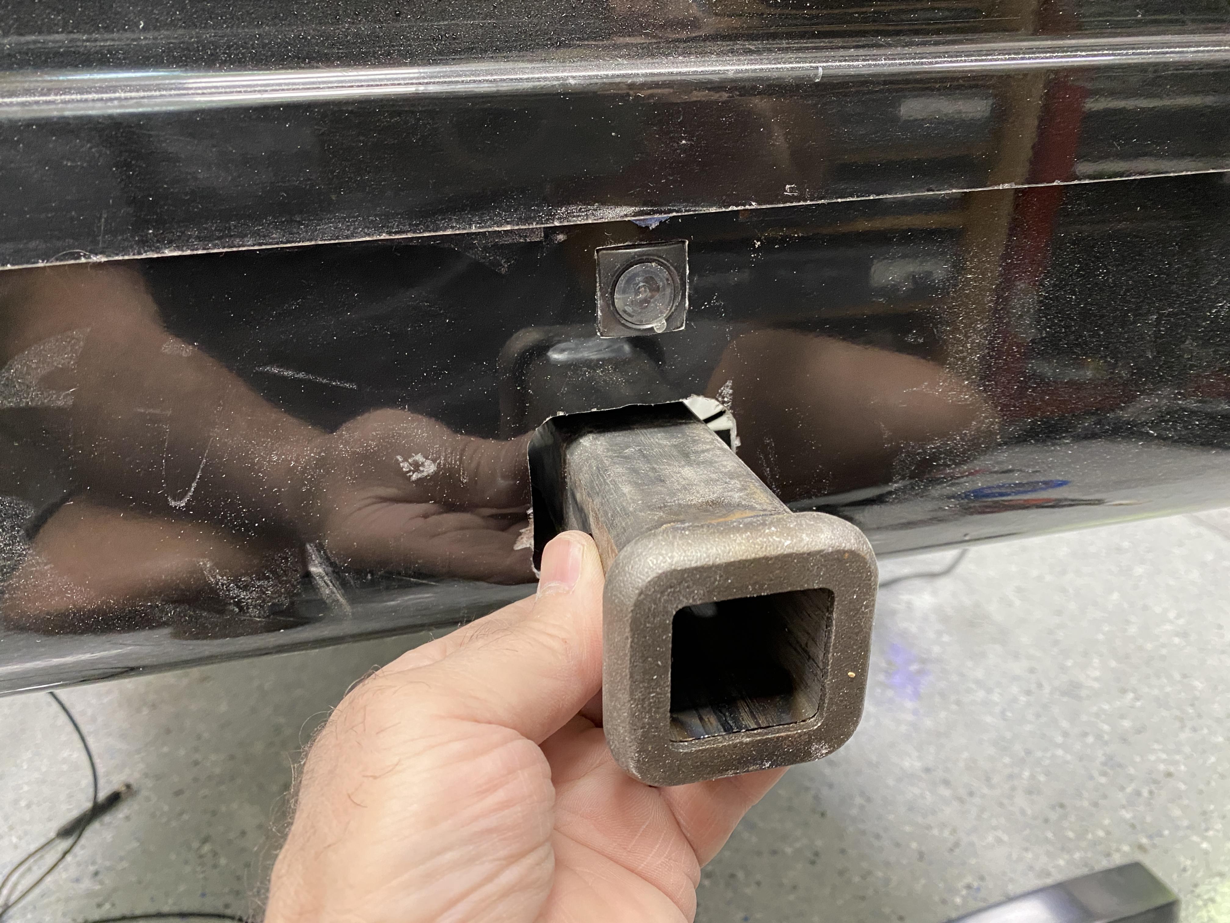
Pic 2 is just a wider angle shot.
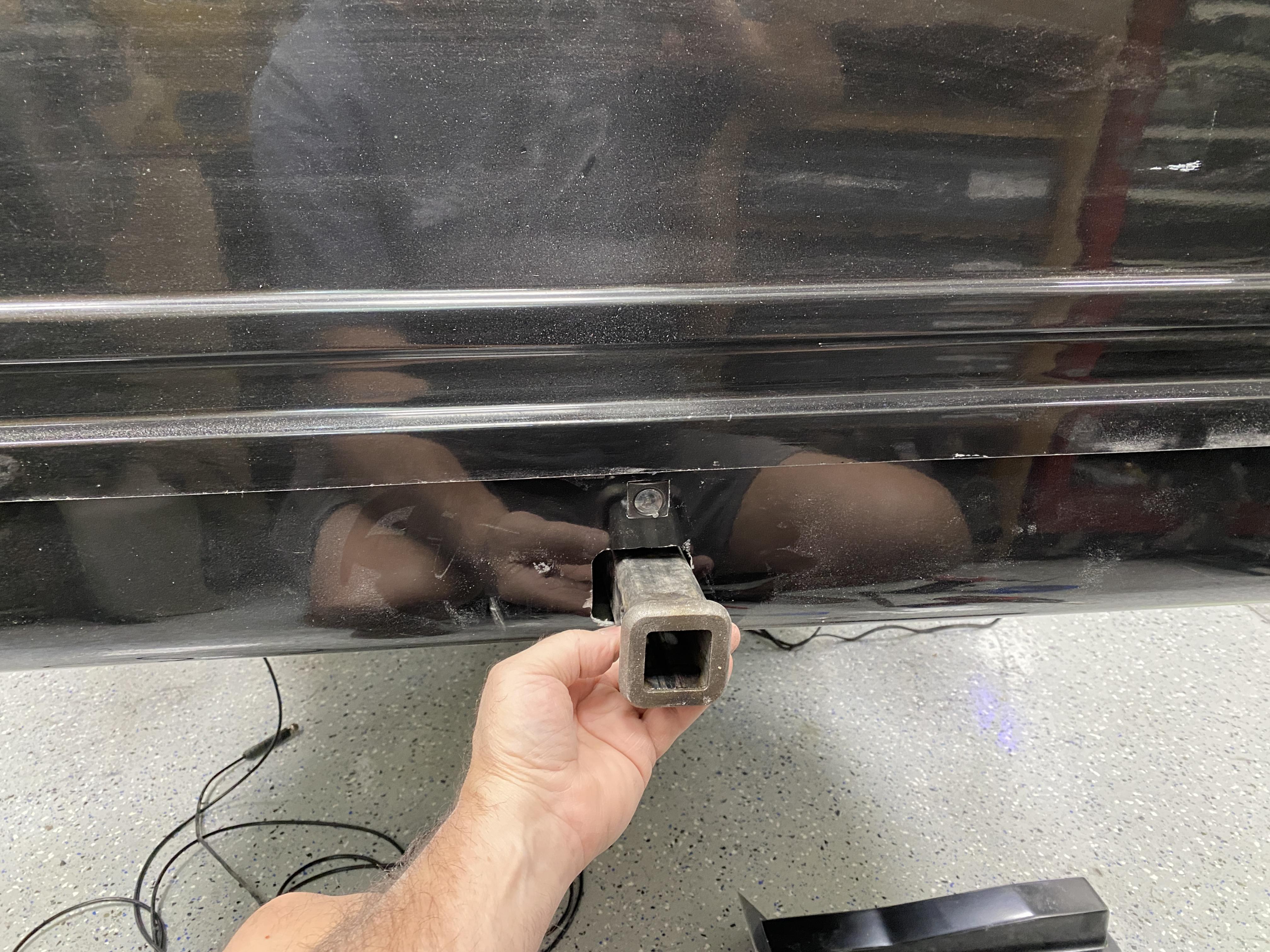
More to come
Mark
-
09-06-2023, 05:45 AM
#182
Senior Member

Quick update.....
I've received a couple PMs asking why "No Updates" on the build....
Well, We had a trip to KS to see oldest son and family and now prepping for a month long RV trip to the New England (Arcadia Nat'l Park/Bar Harbor, then NW Mass, then the Finger Lakes, NY and several other family & friends stops). I'll be back hard at the build by mid Oct.
I ordered and received my backup sensor kit I'll be adding to the rear valance (came with four sensors and a monitor/display. I'll share all that later during the install.
Mark
-
11-16-2023, 08:52 AM
#183
Senior Member

I've been gone for awhile doing some traveling and general "Shop/Garage" cleanup. We have one last trip for Thanksgiving and then I'm back hitting the '35 Truck build and all of you receiving many updates from me.
So stay tuned, back on the air around Nov 29th!
Thx Mark
-
Post Thanks / Like - 0 Thanks, 1 Likes
-
02-04-2024, 01:56 PM
#184
Senior Member

Well, I'm back after several months of doing other "stuff". The weather is warming up and it doesn't take much to warm up the garage to a comfortable working temp with a sweatshirt on.
First up....
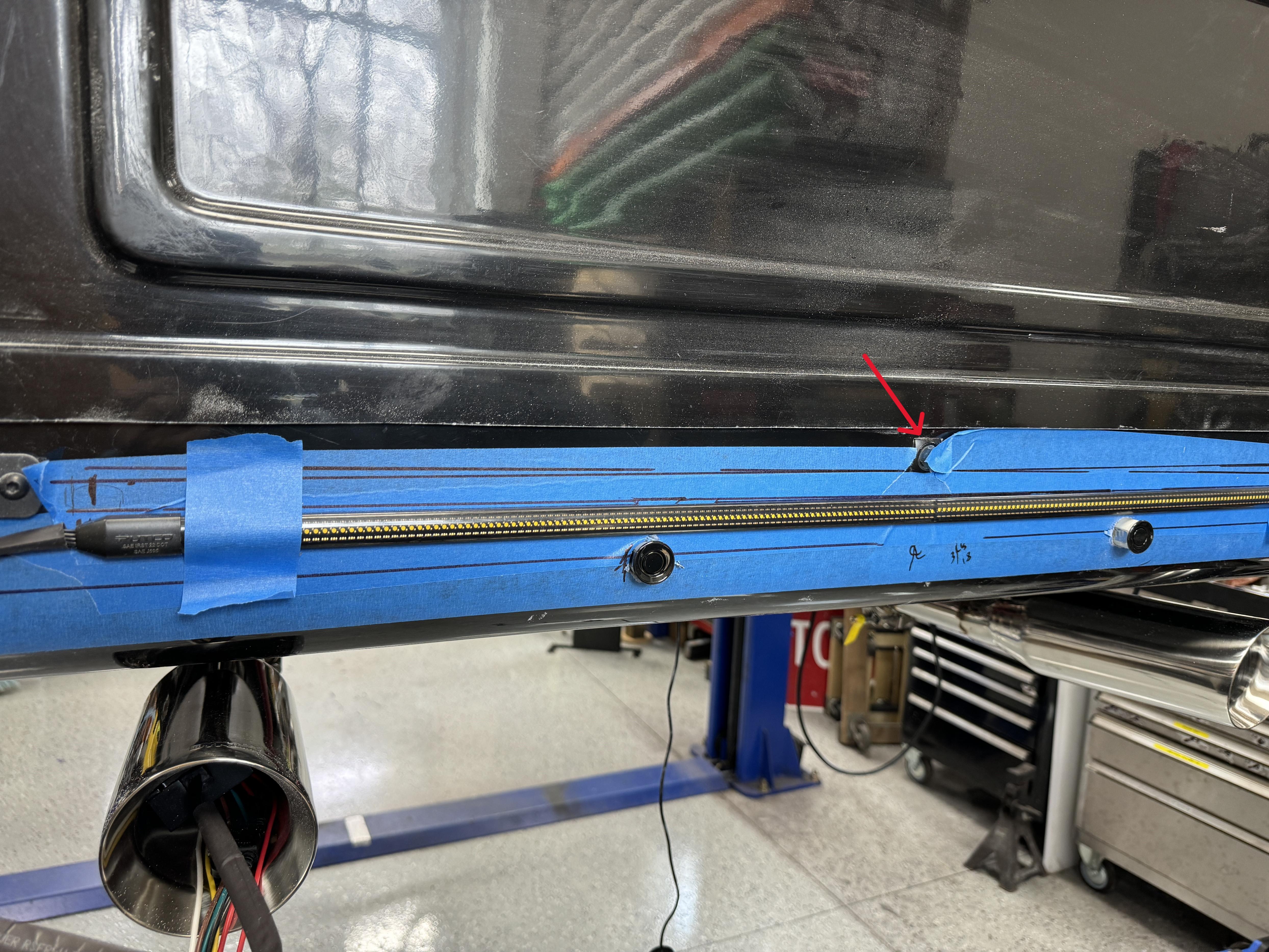
I completed the install of the exhaust tips since I have the raer valance on.... see first photo below.
I also drilled and installed the four backup sensors... photo with 4 red arrows.
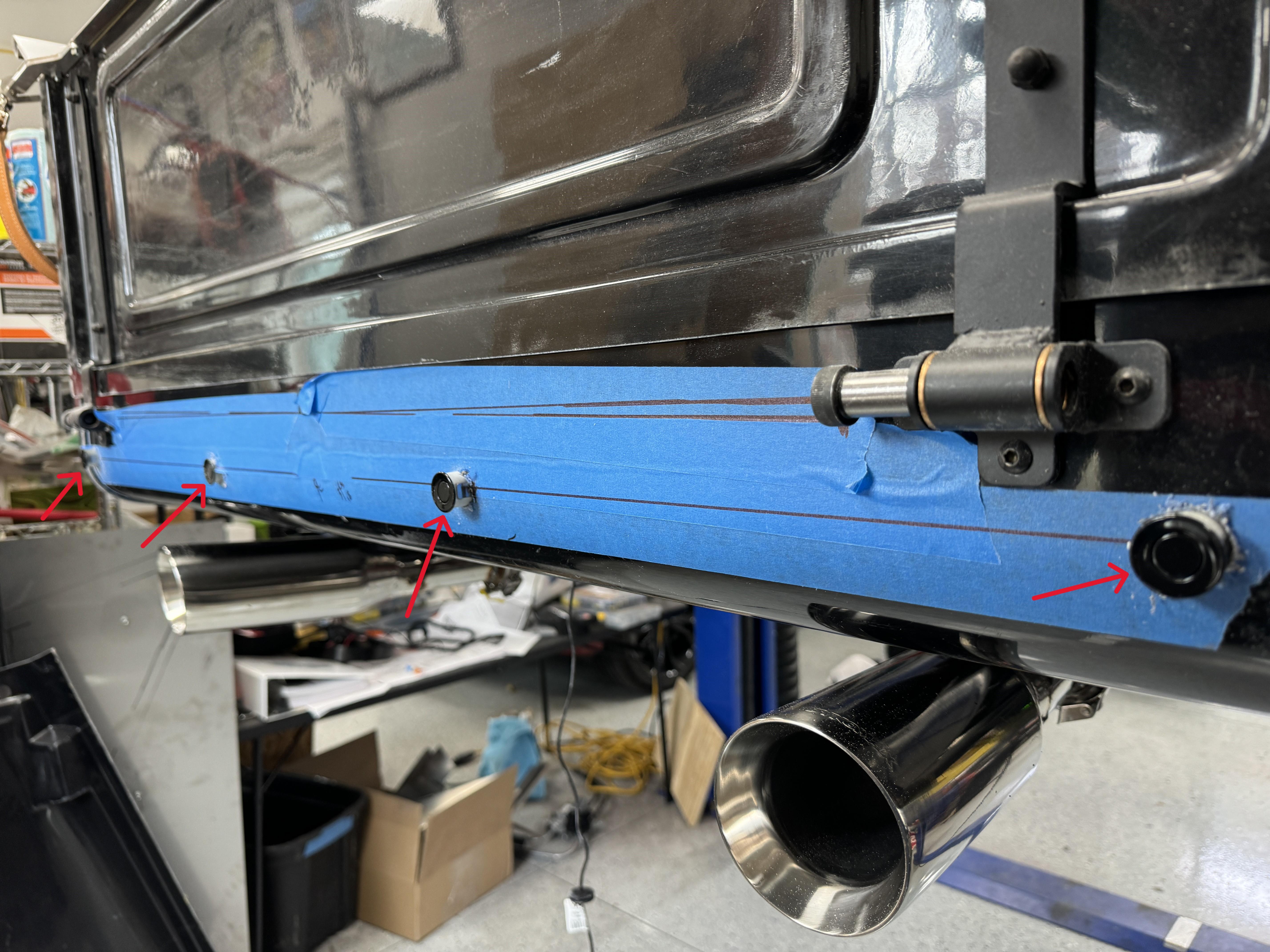
In the cab, I'll have this backup monitor installed (below). I'll have the option to mount forward or rearward and viewed through my review mirror

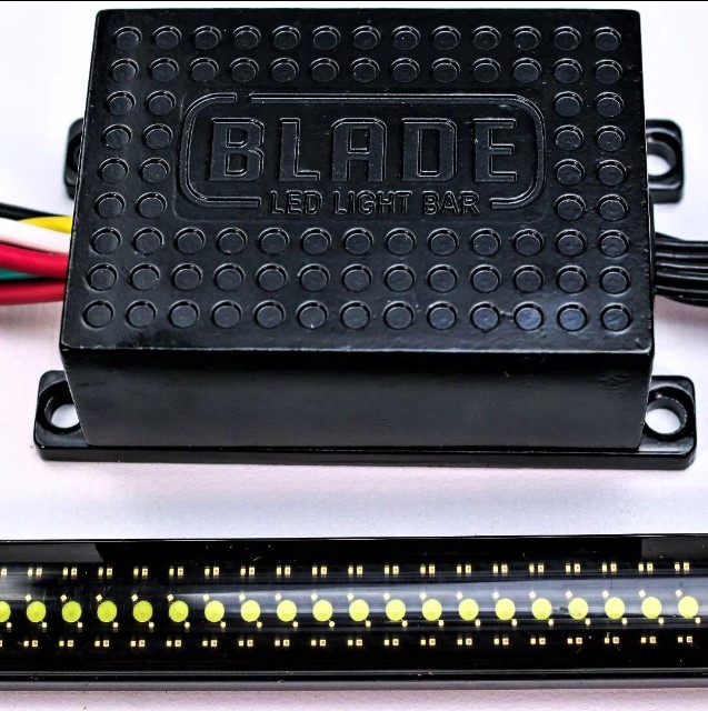
Next up, I installed and prepped the rear valance for my Putco rear valance lightbar.... it will have brake, turn, tail and backup lights. Brake/tail is bright Red, Turn in bright Amber and backup in very bright Clear. This will supplement the stock tail lights that came from FFR and negate me installing a third brake light on the cab..... much cleaner look!
Here's a closeup of the bar and control box
To hide the wiring, I cut a hole that I can slide the light bar through from the backside of the valance
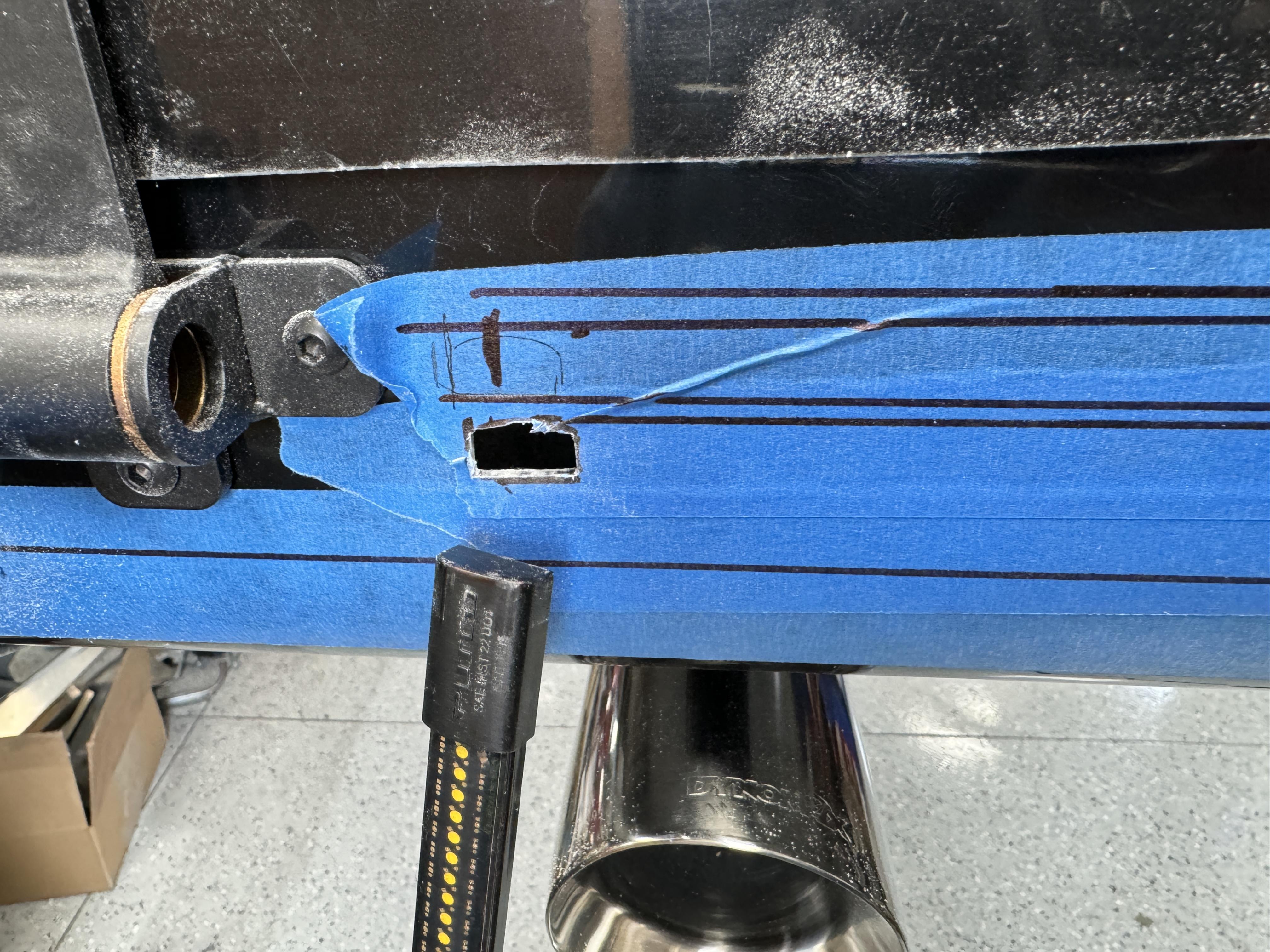
Then, once mounted, as shown below, I'll install some bar light mount clips and the mounted bar will hide the hole I needed to slide the bar through
The hole I cut awhile back for the trailer hitch receiver will be filled in as I changed my mind about installing the hitch.
Lastly, you'll note the red arrow pointing to the review camera.
Stay tune.... lots of updates coming.
Thx Mark
-
02-07-2024, 10:27 AM
#185
Senior Member

Carpet Upgrade prep
I decided to upgrade my carpet. To determine how much I need, I laid out all the cut carpet FFR supplied on my countertop. The most popular carpet size I found is 40" wide. My countertop is 41" wide.
In the first picture, I laid out what would fit on the counter top... i.e, 9' Long and 40" wide
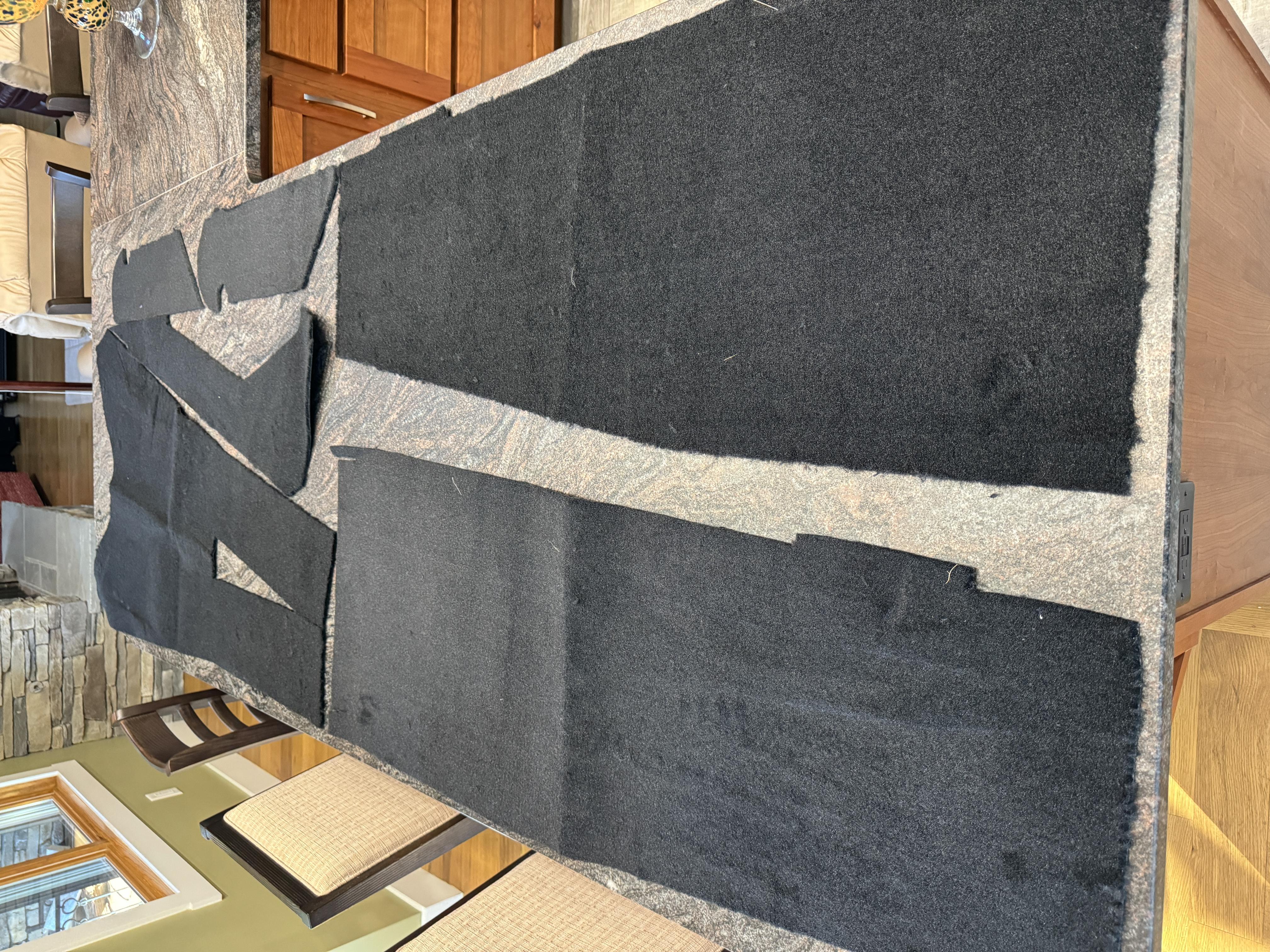
The next photo shows the remaining carpet pieces which measured 7' long and 40" wide
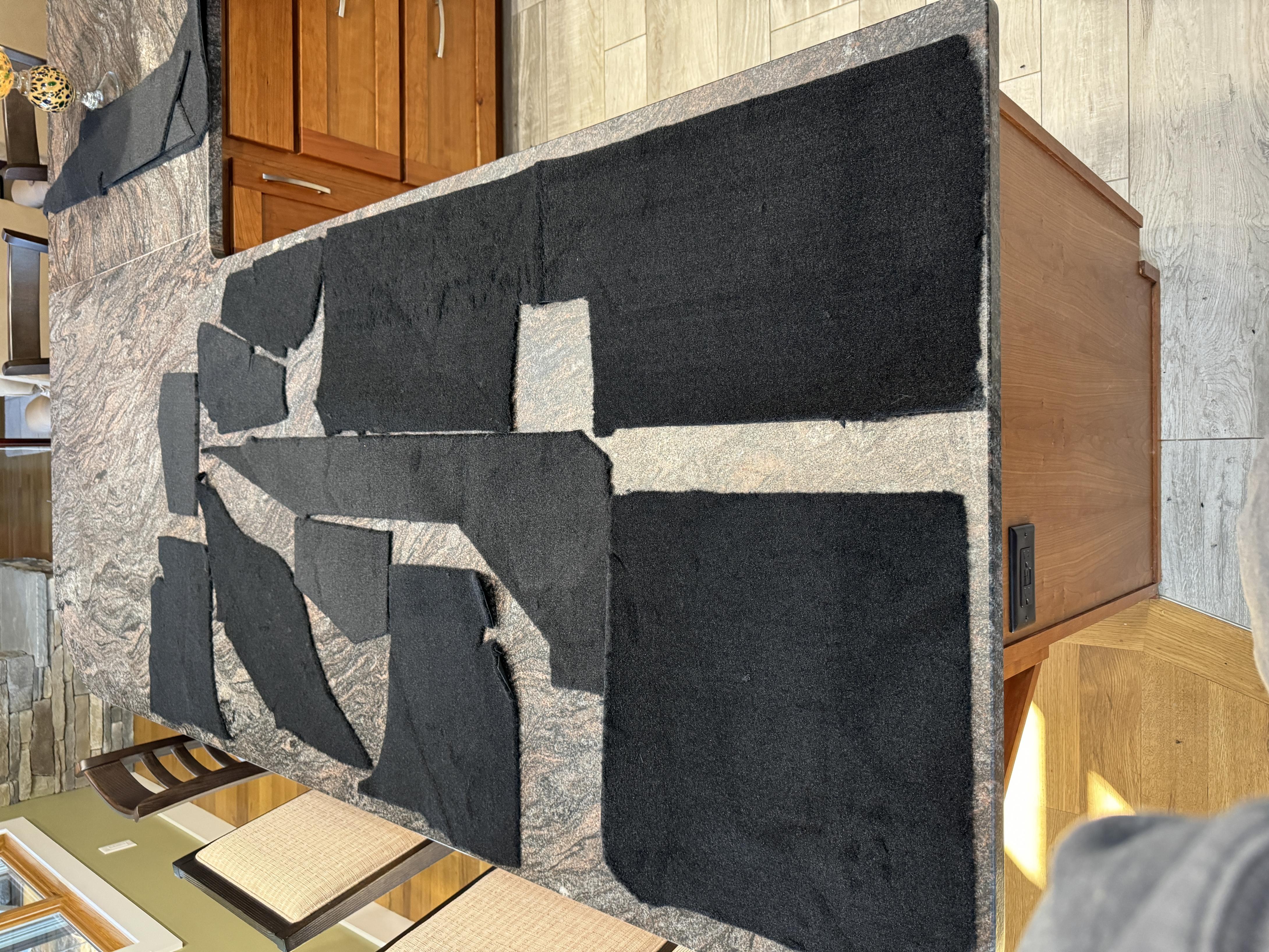
I'm sure if I took more time, I could lay out differently to have less waste, but I'll end up buying 16' long x 40" wide.
Now, just to determine the carpet pile/loop type and purchase.
I'm doing this to have longer carpet life since my truck will be my daily driver.
Mark
-
02-09-2024, 09:40 AM
#186
Senior Member

Misc... Gas Tank pan, door fitting and door internal frame setting
Some quick updates:
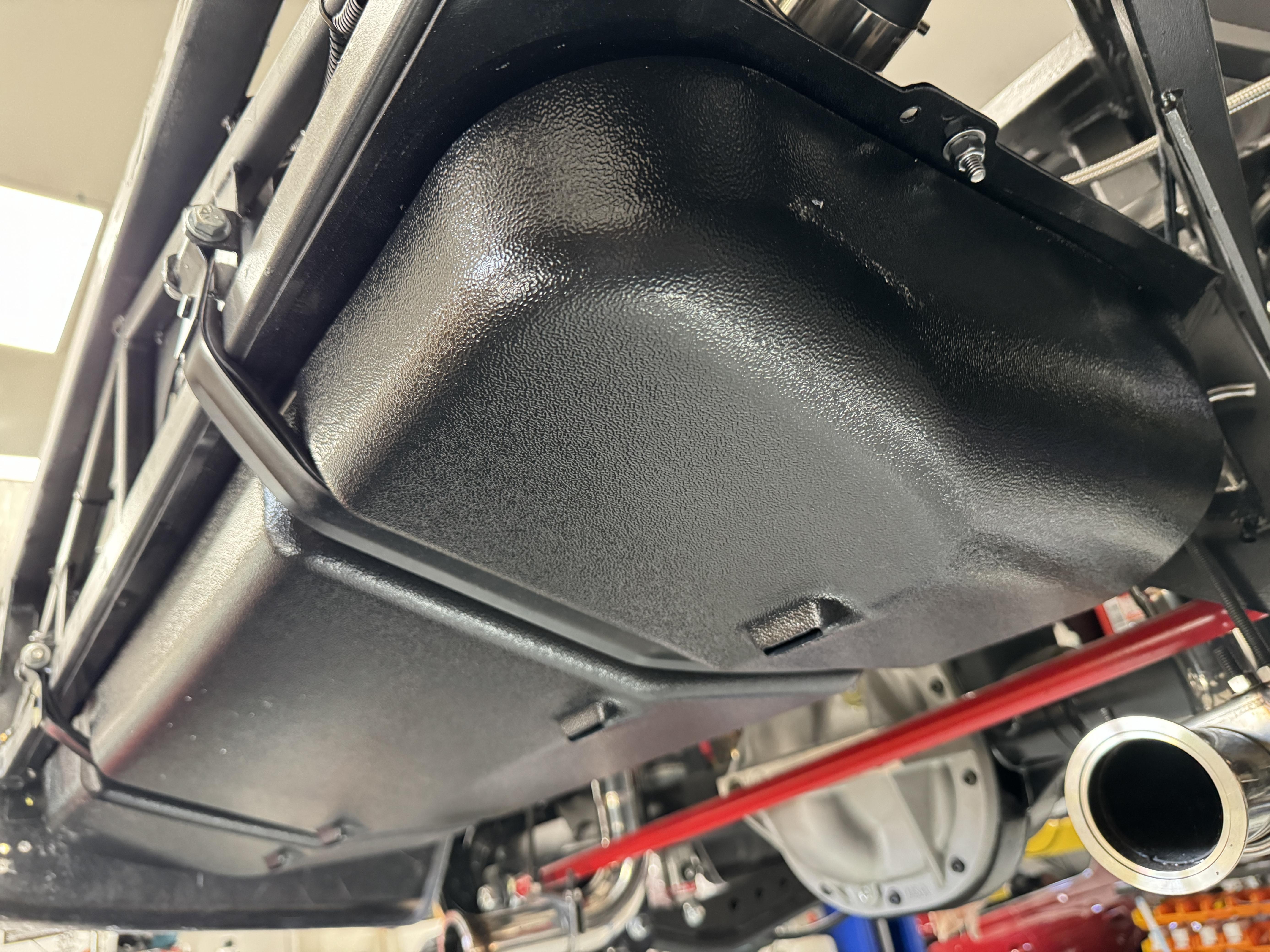
1. After waiting over 7+ months, FFR finally sent me my gas tank pan, so I installed it (one less part in the garage)
2. I got both doors rough fitted in the door openings. I have the "beltline" on the cab/doors aligned and the doors fit into the door openings.
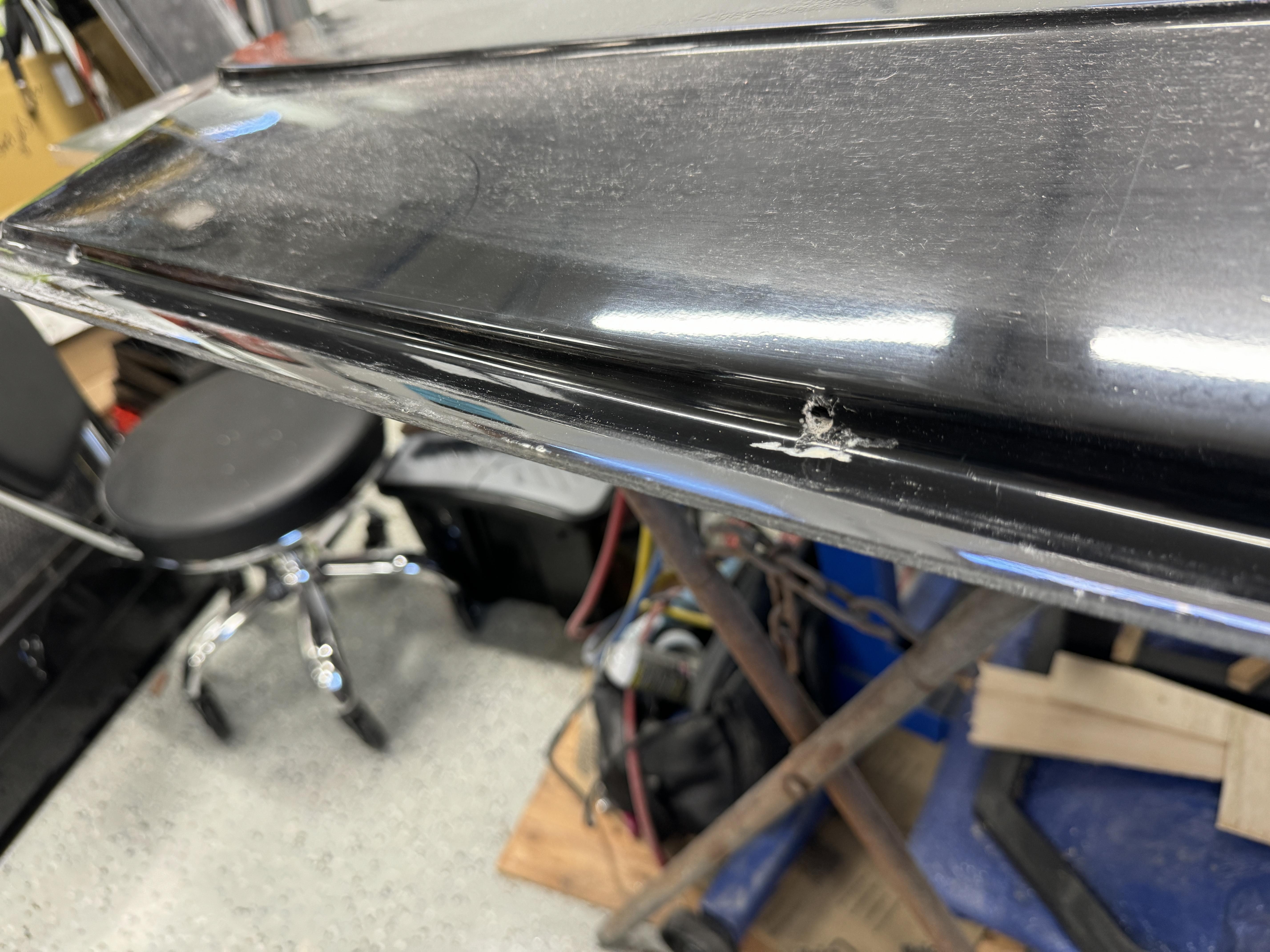
3. I also drilled 3 water drain holes in the bottoms of each door panel
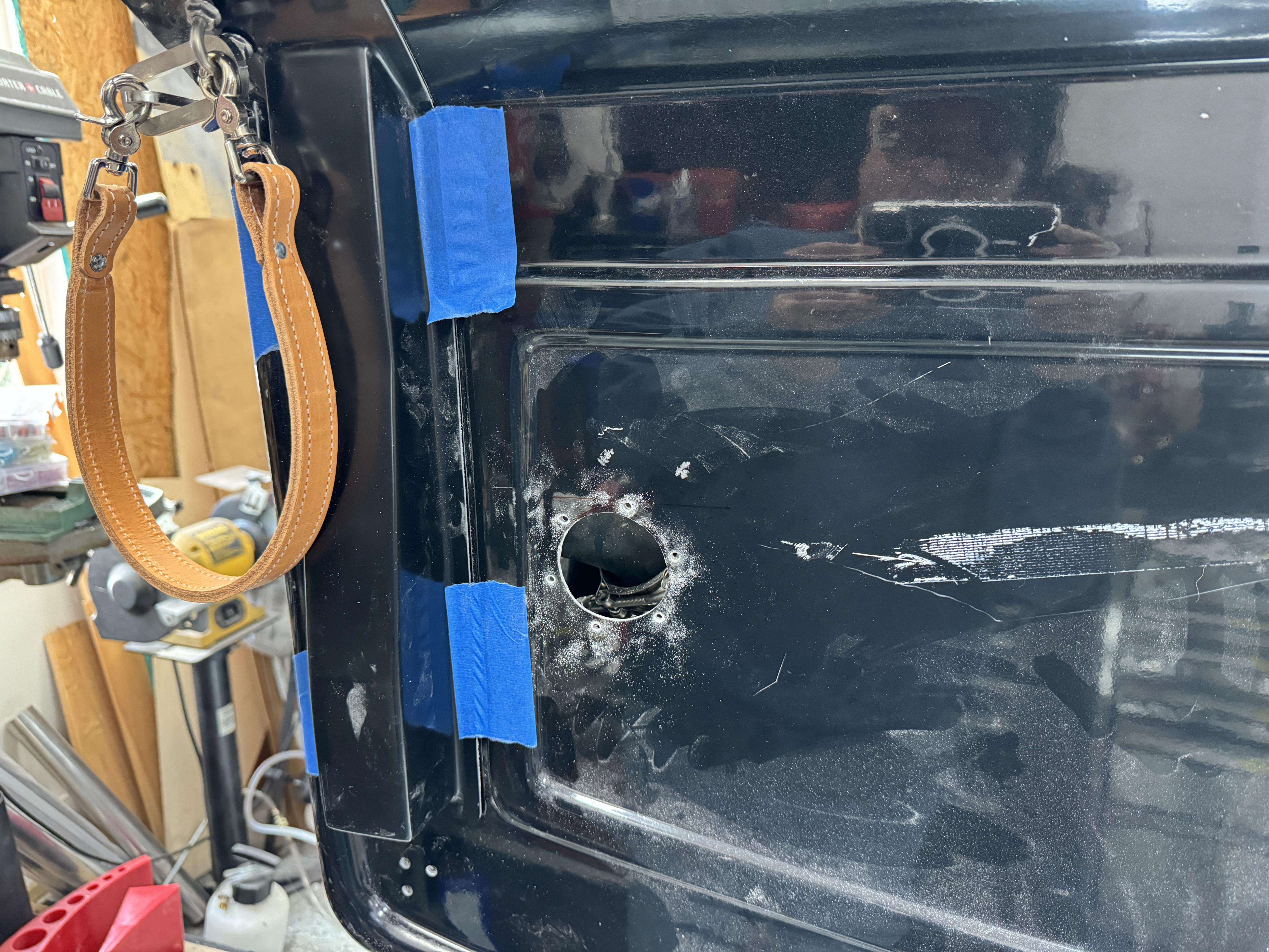
4. For the rear stake pockets, I intend to bond the side pockets (front and rear) to the side bed panels. Since I have to mount the bed side panels to the frame, I'll install some captive nuts to the side panel and install some SS hex pan head bolts from the inside of the truck bed. Lastly, I also intend to make the stake pockets functional by cutting through the SS sheet FFR bonded to the fiberglass bed side and installing black walnut that matches my bed wood and building a side and front rails... I'll document that late with I get to that step.
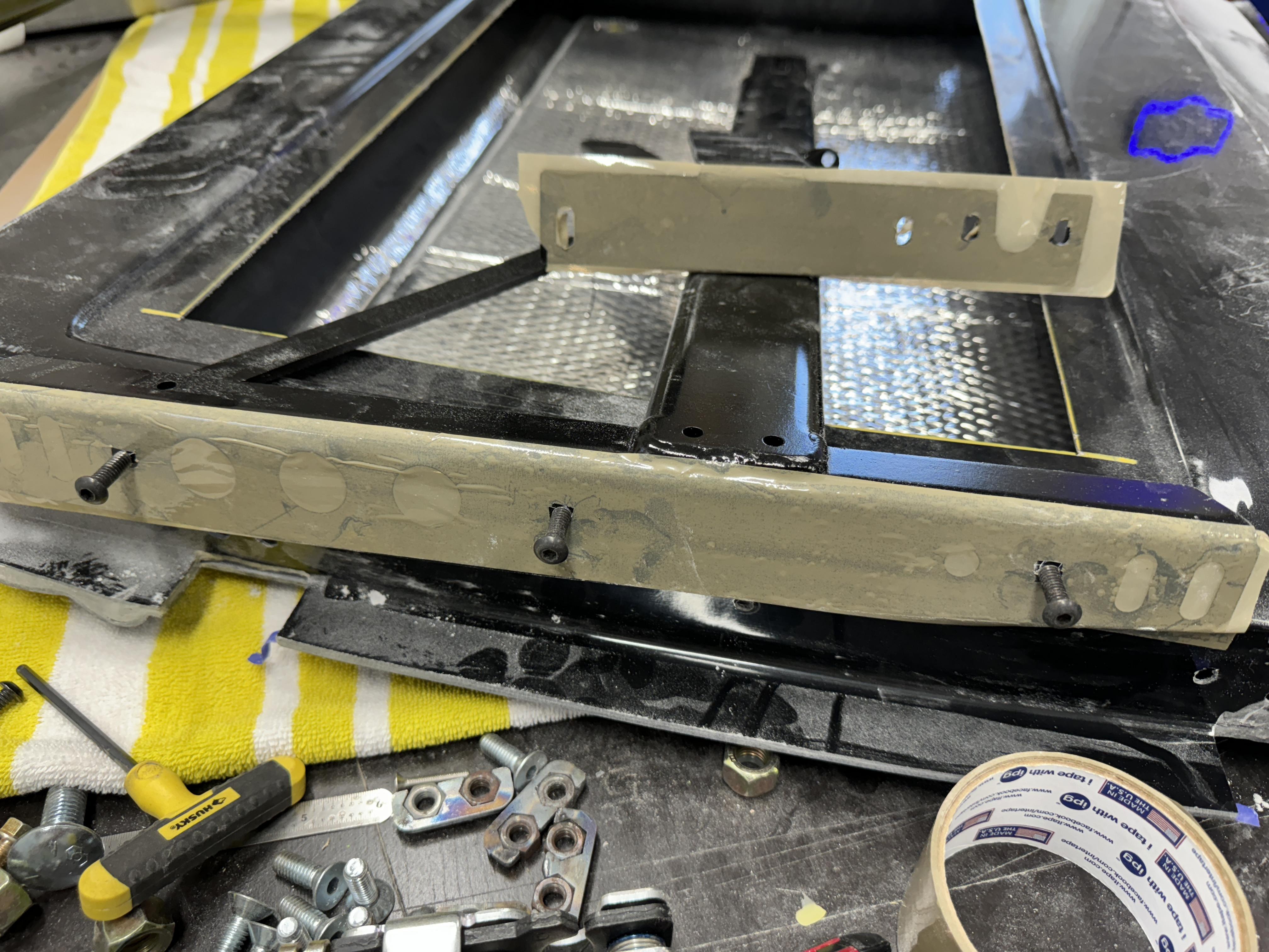
5. For my last update.... I ordered some 3M Urethane gap filling bonding epoxy for the doors internal steel support framing (for the door hinges and latch. Since the fiberglass inside the doors are not uniform/flat, when you tighten the hinge and door latch bolts, the fiberglass will twist/buckle/distort. The epoxy will act as a "bedding" material. If I ever have to remove the steel framing, I installed some plastic box tape to the steel which will prevent the steel being stuck to the epoxy. While the epoxy is still wet, I'll just snug the bolts, let the epoxy set and then do the final tightening of the bolts. Take note I drilled and taped the frame to attach to the door panels (the same locations from the FFR template where they suggested using pop rivets).
Stay tuned,
Mark
-
Post Thanks / Like - 1 Thanks, 2 Likes
-
02-10-2024, 09:44 AM
#187
Senior Member

-
Post Thanks / Like - 0 Thanks, 1 Likes
-
02-12-2024, 09:57 AM
#188
Senior Member

HELP.... Advice needed on Door alignment!
OK, I'm needing some help and advice on how to deal with some passenger door alignment. My Driver's door came out great.
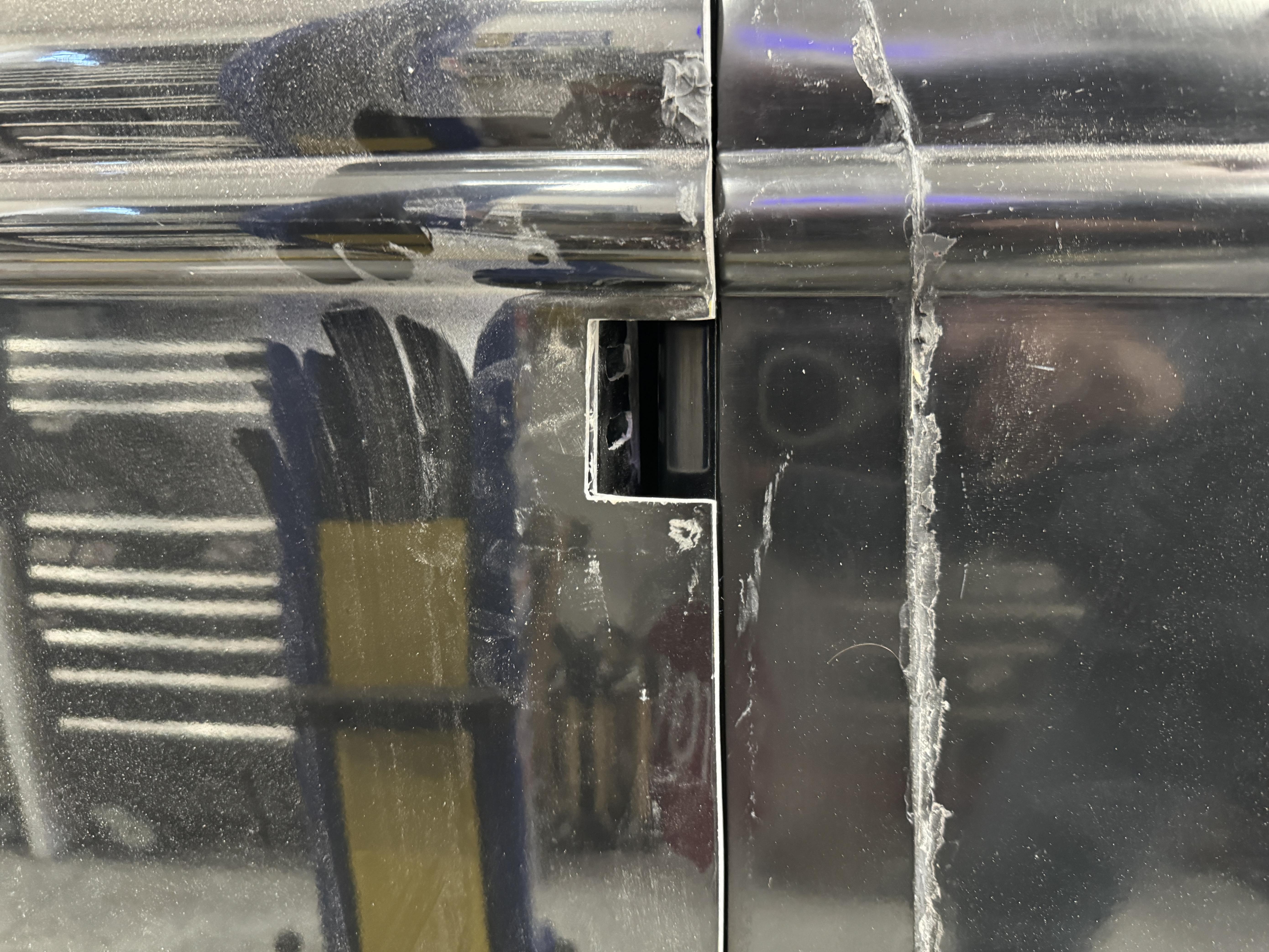
First.... let me state the bottom half of the passenger door, i.e., below the beltline/window, aligns perfect at the front, bottom and rear. As you'll see in both pictures my issue is with the top of the door.
Specifically, the back of the door window frame sticks out:
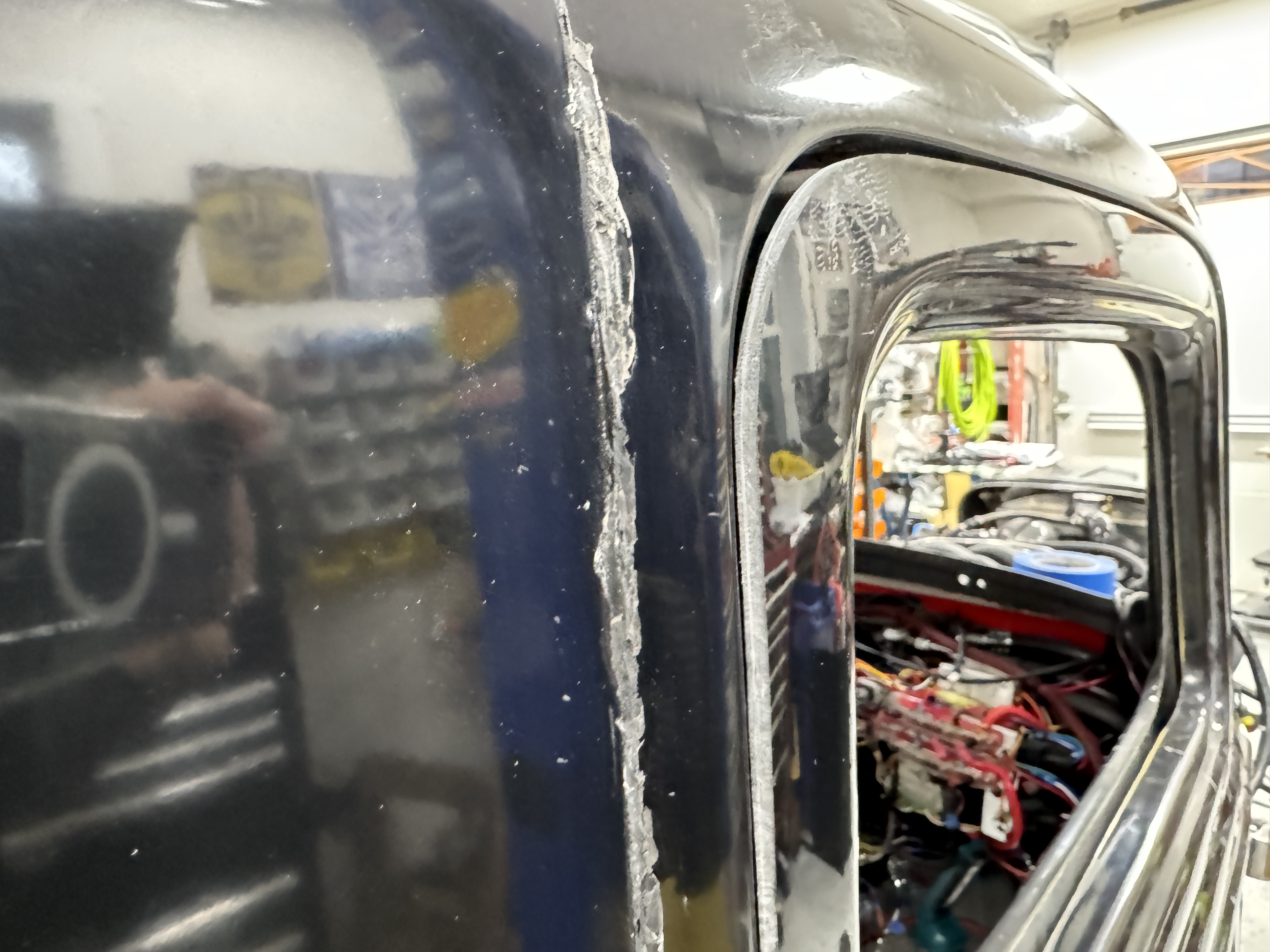
And the front of the door window frame sticks in:
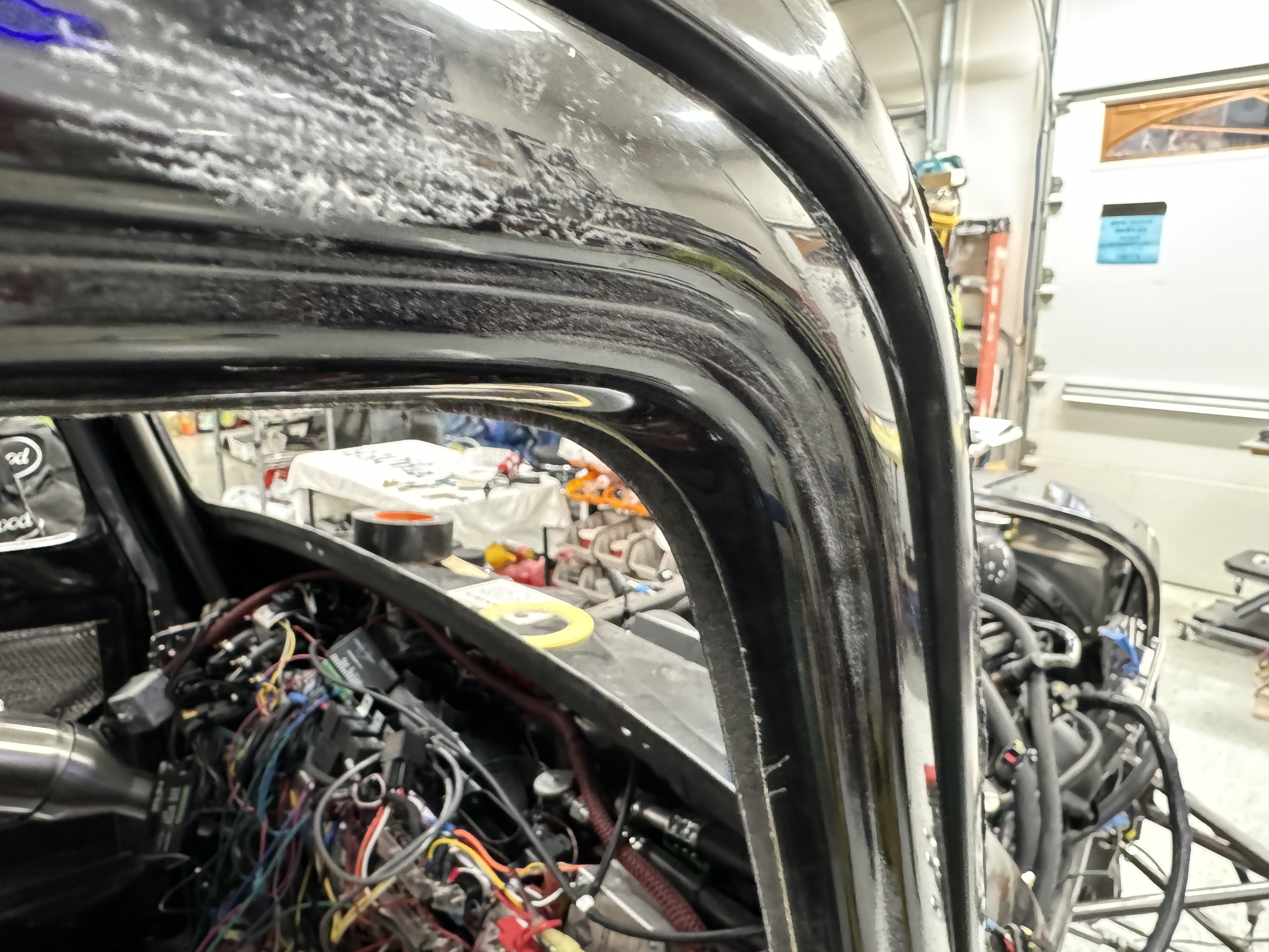
Basically, the top half of the door seems "twisted", i.e., the back it out about 1/4" and the front is in about 1/4"
Are there any tricks of the trade? Will the window glass, once installed, help to fix this? Any advice MOST WELCOME as I'm at a lost on how to resolve this.
Thanks Mark
Last edited by mkassab; 02-12-2024 at 09:59 AM.
-
02-12-2024, 12:26 PM
#189
Senior Member

The truck door fitting... probably the hardest and for most including me the most challenging. I was wondering whether the new extended cab doors would fit better than the original version I build. Mine fit OK around the window frame but the bottom rear corners both stuck out. I had to pie cut the fiberglass and mostly fixed it. I don't have any magic answers for you. But did want to respond to your question of whether the glass would help fix. In my experience, it won't. So there's that.
Build 1: Mk3 Roadster #5125. Sold 11/08/2014.
Build 2: Mk4 Roadster #7750. Sold 04/10/2017.
Build Thread
Build 3: Mk4 Roadster 20th Anniversary #8674. Sold 09/07/2020.
Build Thread and
Video.
Build 4: Gen 3 Type 65 Coupe #59. Gen 3 Coyote. Legal 03/04/2020.
Build Thread and
Video
Build 5: 35 Hot Rod Truck #138. LS3 and 4L65E auto. Rcvd 01/05/2021. Legal 04/20/2023.
Build Thread. Sold 11/9/2023.
-
02-12-2024, 01:39 PM
#190
Senior Member


Originally Posted by
edwardb

The truck door fitting... probably the hardest and for most including me the most challenging. I was wondering whether the new extended cab doors would fit better than the original version I build. Mine fit OK around the window frame but the bottom rear corners both stuck out. I had to pie cut the fiberglass and mostly fixed it. I don't have any magic answers for you. But did want to respond to your question of whether the glass would help fix. In my experience, it won't. So there's that.
Thanks Paul. I'll keep at it. I may have to build up the outside of the front part of the door with filler or put a bumper inside the upper part of the door jam to push the top corner of the window frame out?.... And, as you did, pie cut the rear bottom of the window frame for the rear upper corner to be pushed in.
Note: I also had the lower rear corner of both doors stick out as you did, but found a solution. You can loosen the two carriage bolts on the inter door cross frame (close to the door latch).... then while loose, push the bottom corner of the door in and the top of the door corner out. This causes a "twist" of the rear of the door. Then while doing this, tighten the two cross member carriage bolts and that fixed the lower corner sticking out.
Mark
-
02-12-2024, 01:51 PM
#191

Originally Posted by
mkassab

Thanks Paul. I'll keep at it. I may have to build up the outside of the front part of the door with filler or put a bumper inside the upper part of the door jam to push the top corner of the window frame out?.... And, as you did, pie cut the rear bottom of the window frame for the rear upper corner to be pushed in.
Note: I also had the lower rear corner of both doors stick out as you did, but found a solution. You can loosen the two carriage bolts on the inter door cross frame (close to the door latch).... then while loose, push the bottom corner of the door in and the top of the door corner out. This causes a "twist" of the rear of the door. Then while doing this, tighten the two cross member carriage bolts and that fixed the lower corner sticking out.
Mark
Hey Mark, I cut the inner panels horizontally along the line of the cut out so the top of the door could flex out and then fiberglassed back together when in the right position. Kind of the reverse of what Paul did at the bottom. I also found the bottoms can be adjusted by pushing in and tightening.
Last edited by Lew; 02-12-2024 at 02:09 PM.
Reason: Correction
-
02-12-2024, 02:05 PM
#192
Senior Member


Originally Posted by
Lew

Hey Mark, I cut the inner panels horizontally near the bottom of the windows so the top of the door could flex out and then fiber glassed back together when in the right position. Kind of the reverse of what Paul did at the bottom. I also found the bottoms can be adjusted by pushing in and tightening.
Thanks Lewis.... I was also thinking the same thing. Another possible solution I was thinking about, if it's possible I might add, is to separate the outer and inner panels, cause the twist needed, and re-bonding the two panels using the 3M urethane epoxy.
Mark
-
02-12-2024, 02:12 PM
#193
I decided that there wasn’t enough meat there to cut them apart and bond back together. Note that I changed the location of the cuts in my previous post.
-
02-13-2024, 07:52 AM
#194
Senior Member

-
02-14-2024, 08:51 AM
#195
Senior Member

Door Latch Post/Stud issues 1 of 2
All this Door fitting will be the death of me.... but I will prevail.
As I stated in the above post, the doors are trimmed and fitted. Yesterday, I started the add the latch posts/studs. I thought this would take an hour and ended up half a day for two damn latch studs! Let me explain.
I need two posts to detail several different issues between the passenger and driver's door.
First up, the Left/Passenger Door.
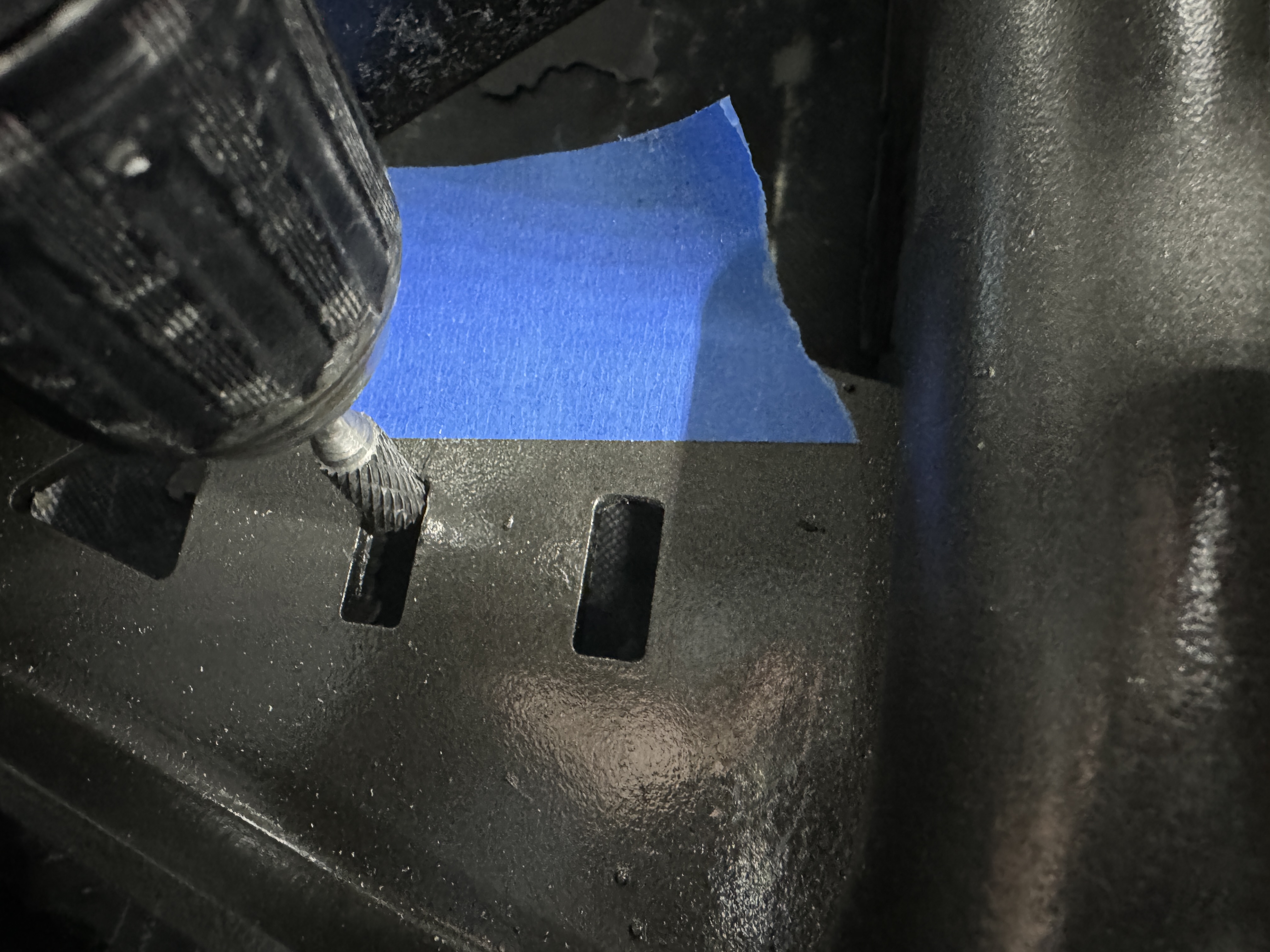
In mocking up the pass door, I quickly discovered that the latch post/stud mounting hole was too high and the slots to lower it were high and prevented me to lower the latch stud mounting plate. I chose to elongate the two mount plate slots. I used two methods, i.e., a carbide burr bit and my belt sander. The first picture is the burr.
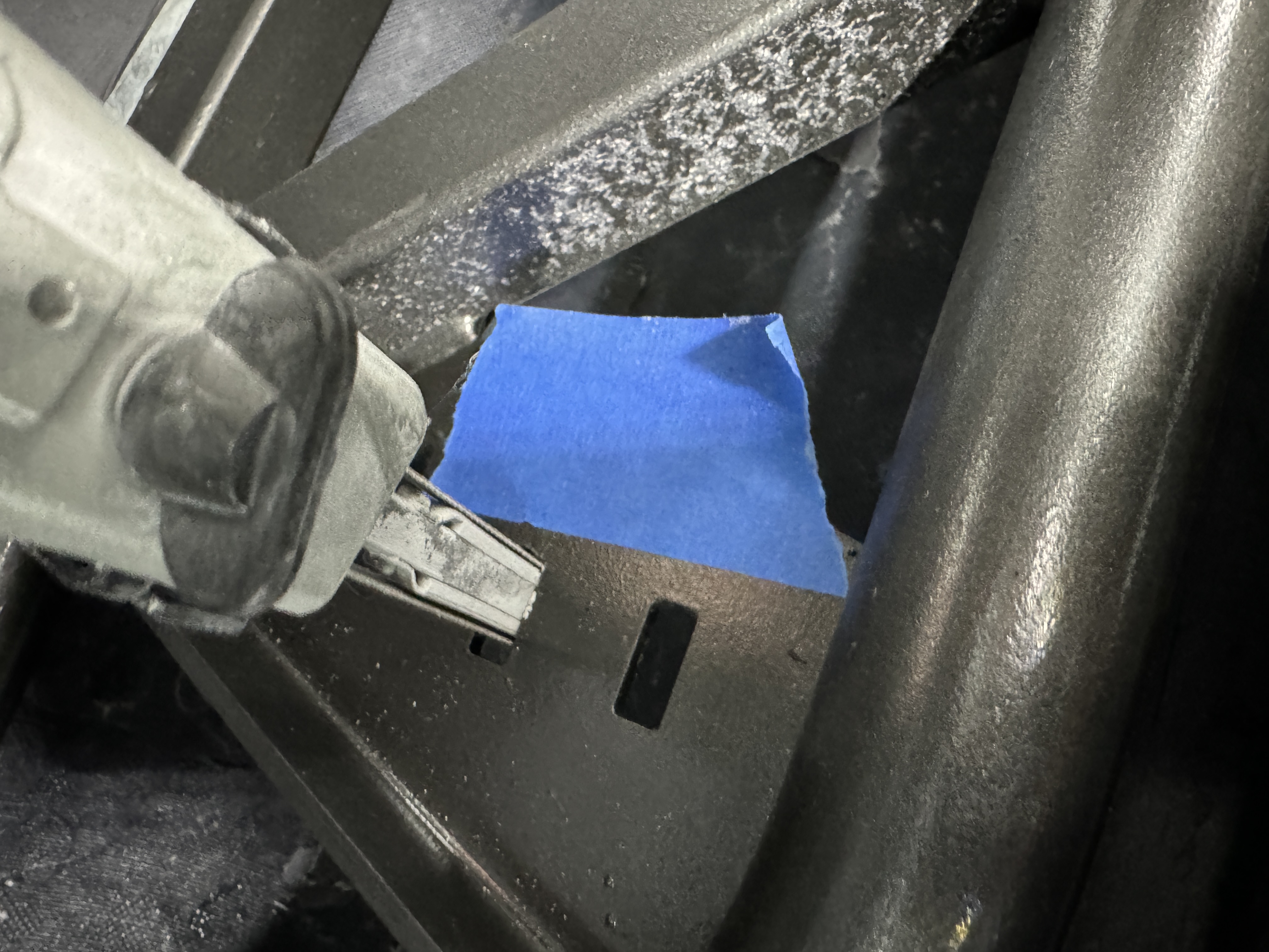
The next picture is my thin belt sander.
This picture shows the elongated slots and mounting bolts (Sorry, the pic is upside down... but you get the "picture").
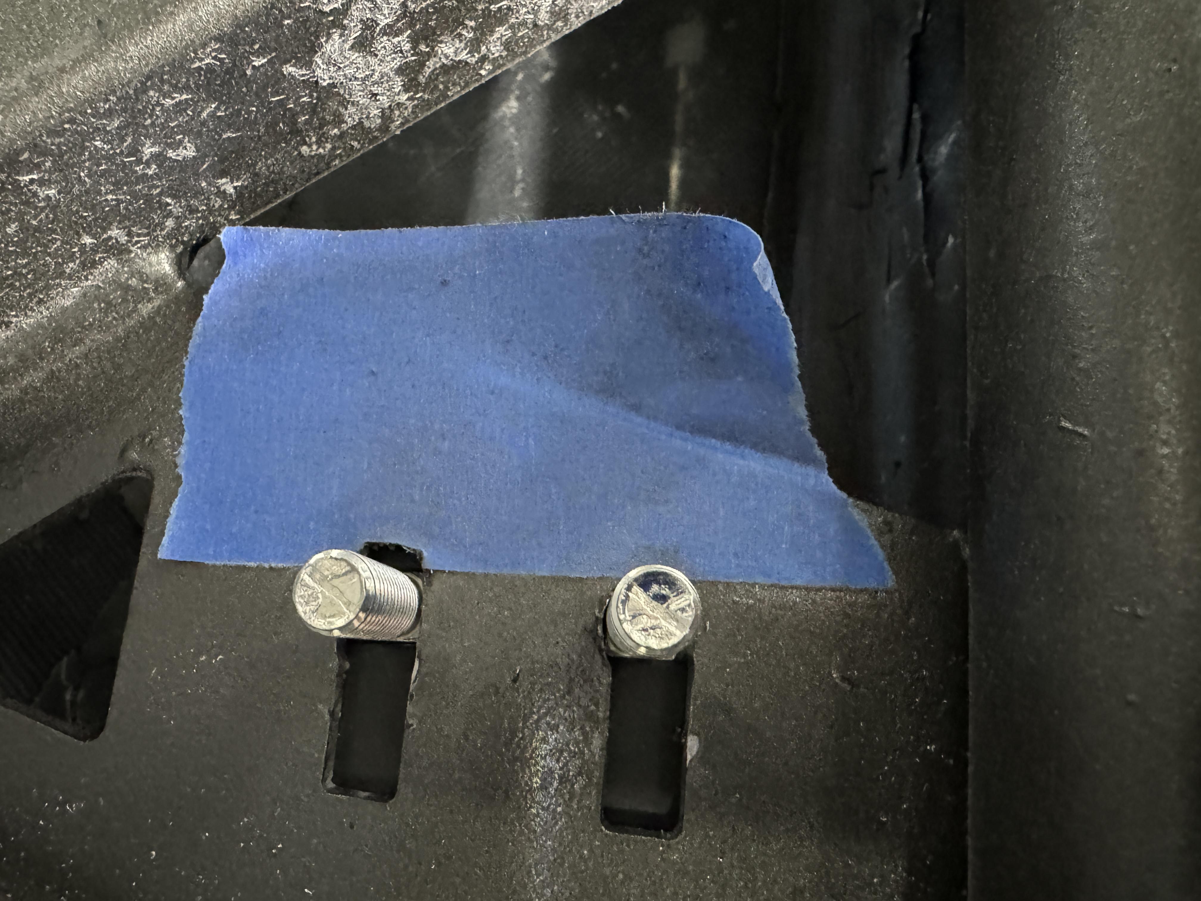
Then my next issue was apparent... the latch stud was too short, and the head of the stud prevented the latch from closing. So, to lengthen the latch stud, I added two SS washers
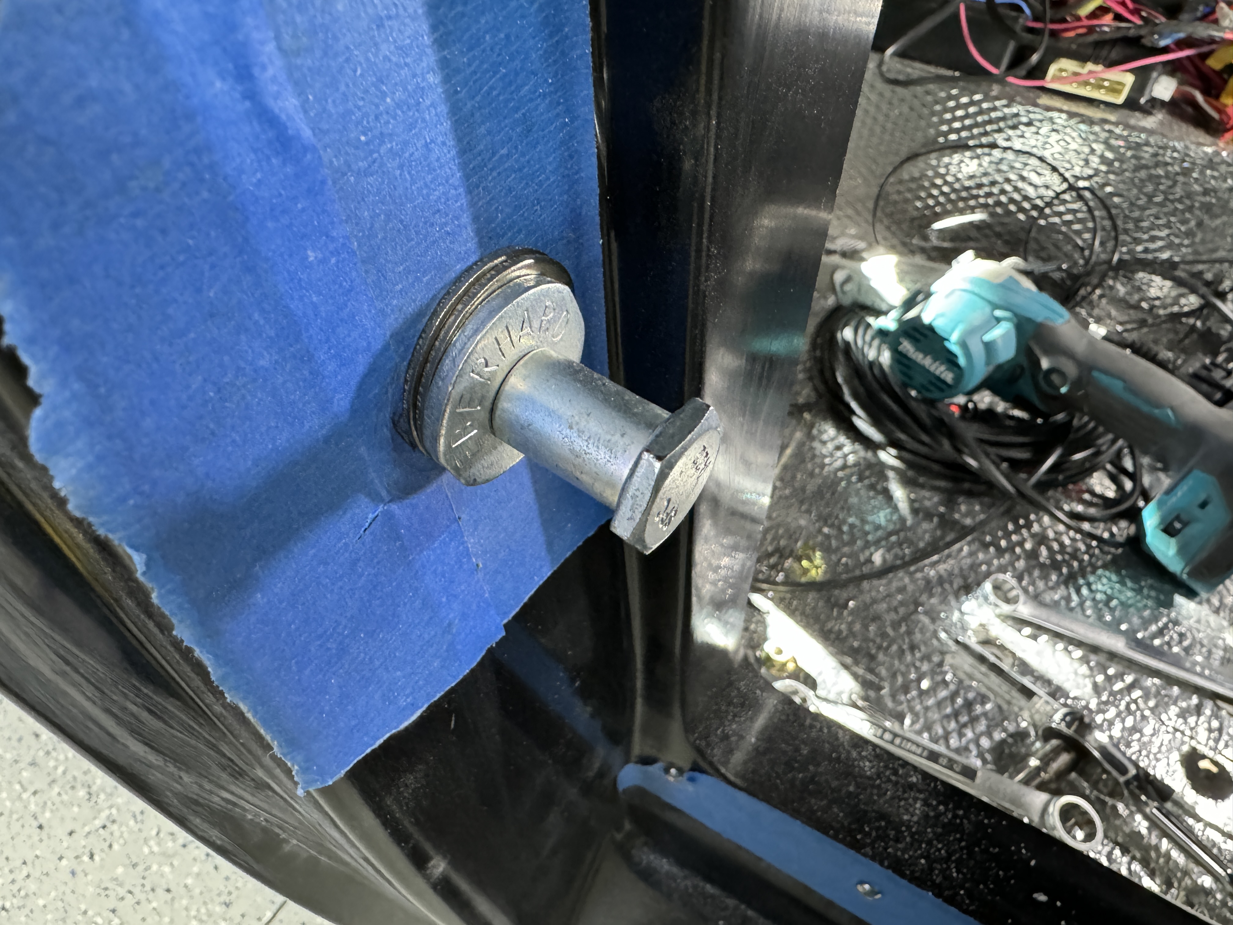
With the passenger door now latching properly, I moved on to the Driver's door for different issues.... see next post.
to be continued.... Mark
-
02-14-2024, 09:27 AM
#196
Senior Member

Door Latch Post/Stud issues 2 of 2
So, the first issue with the Driver's door, is the same issue as the Passenger door, i.e., the mount plate slots needed to be elongated the same as the passenger side.... so, I won't repeat that part (refer to last post).
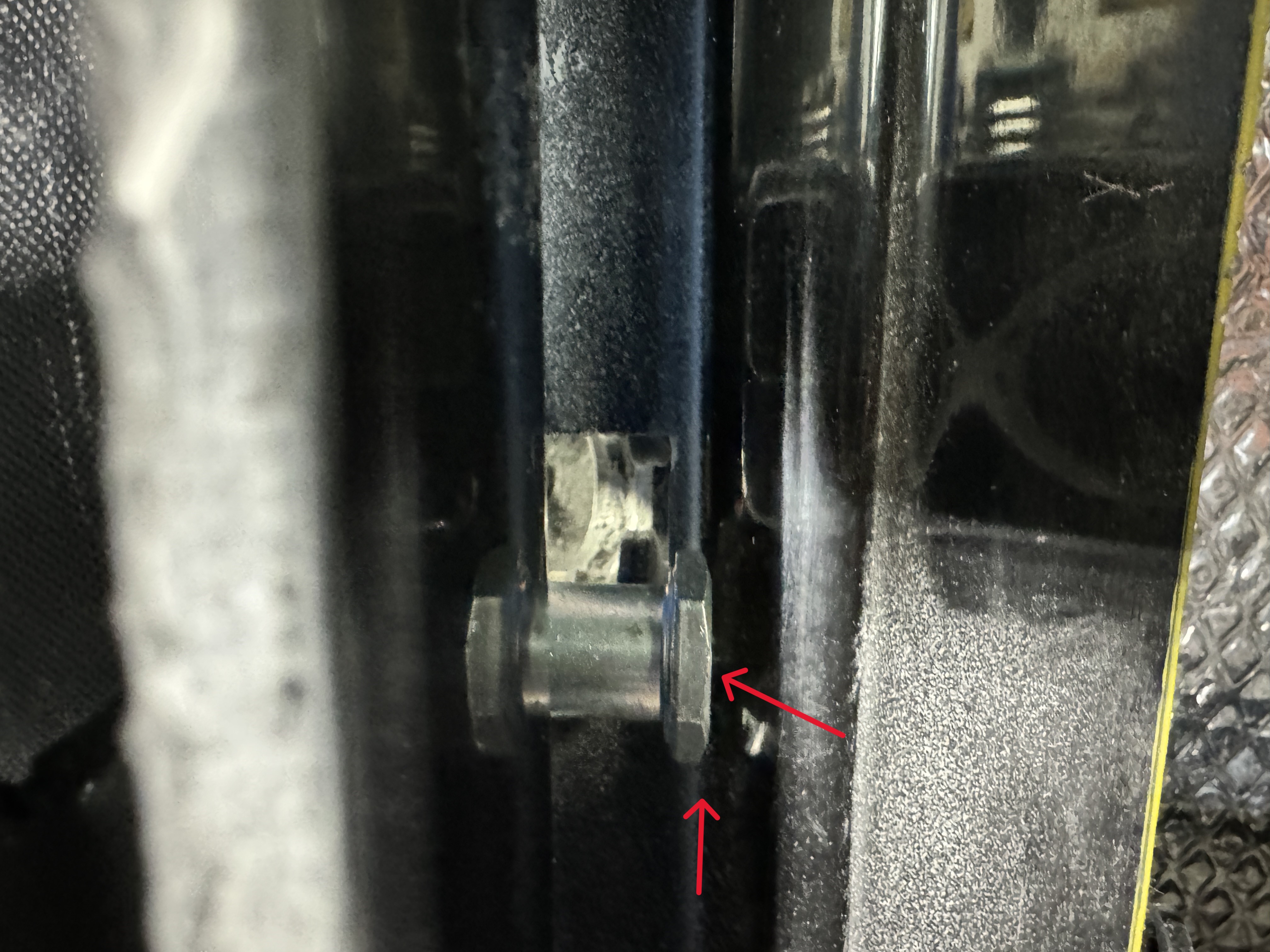
My next issue was the opposite of the latch stud from the Passenger side.... the latch stud is now was too long (vs too short like the passenger side). You can't make this stuff up.
See the red arrows showing the latch stud hitting the door panel.
To shorten the latch post / stud is not easy. First, I had to remove the washer that does not side off the stud. I had to cut the washer on both sides to bend and remove it. I used my small reciprocating saw for those cuts.
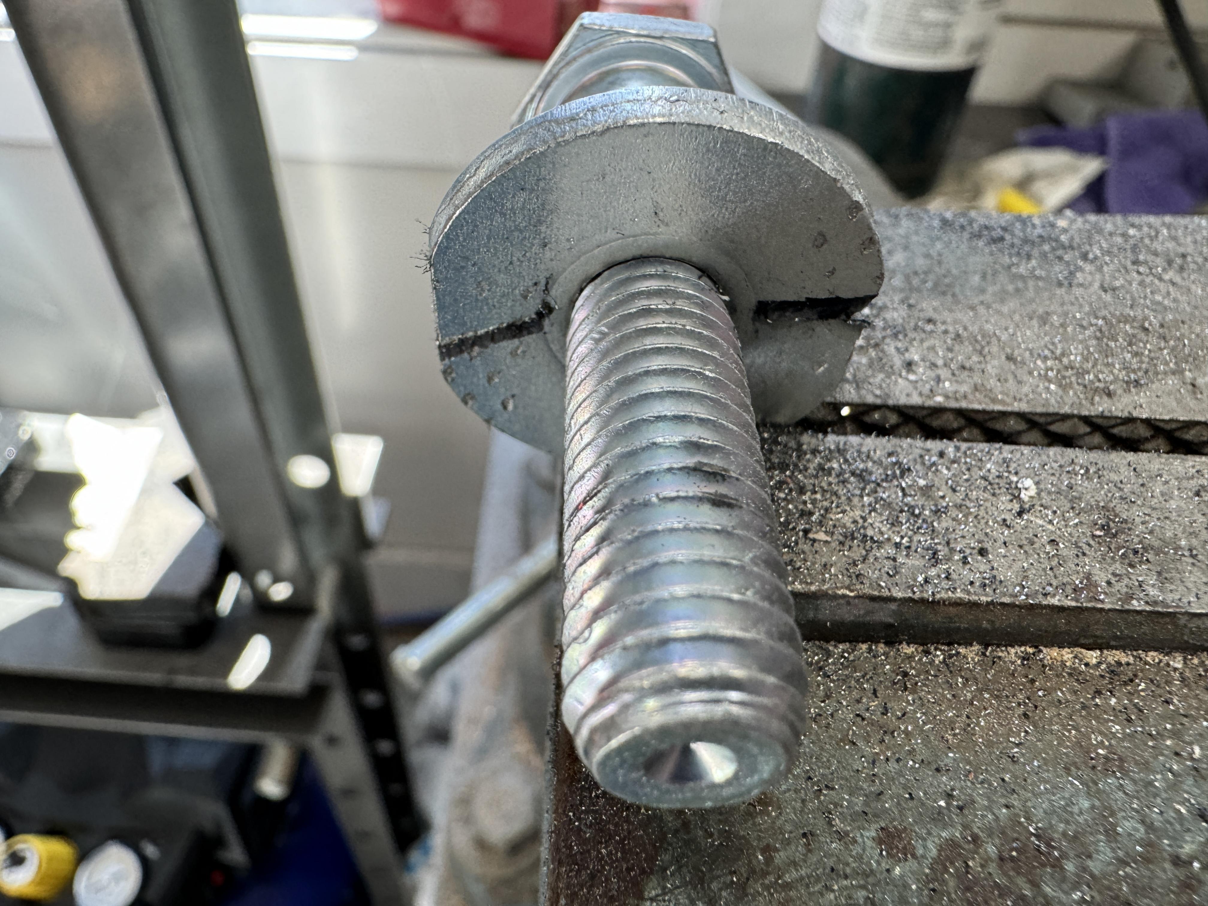
Next, I had to shorten the shoulder on the latch stud. Not an easy task without a "real" lathe.
So, I started with my Dremel tool with a cutting disc (sorry the pic is upside down).
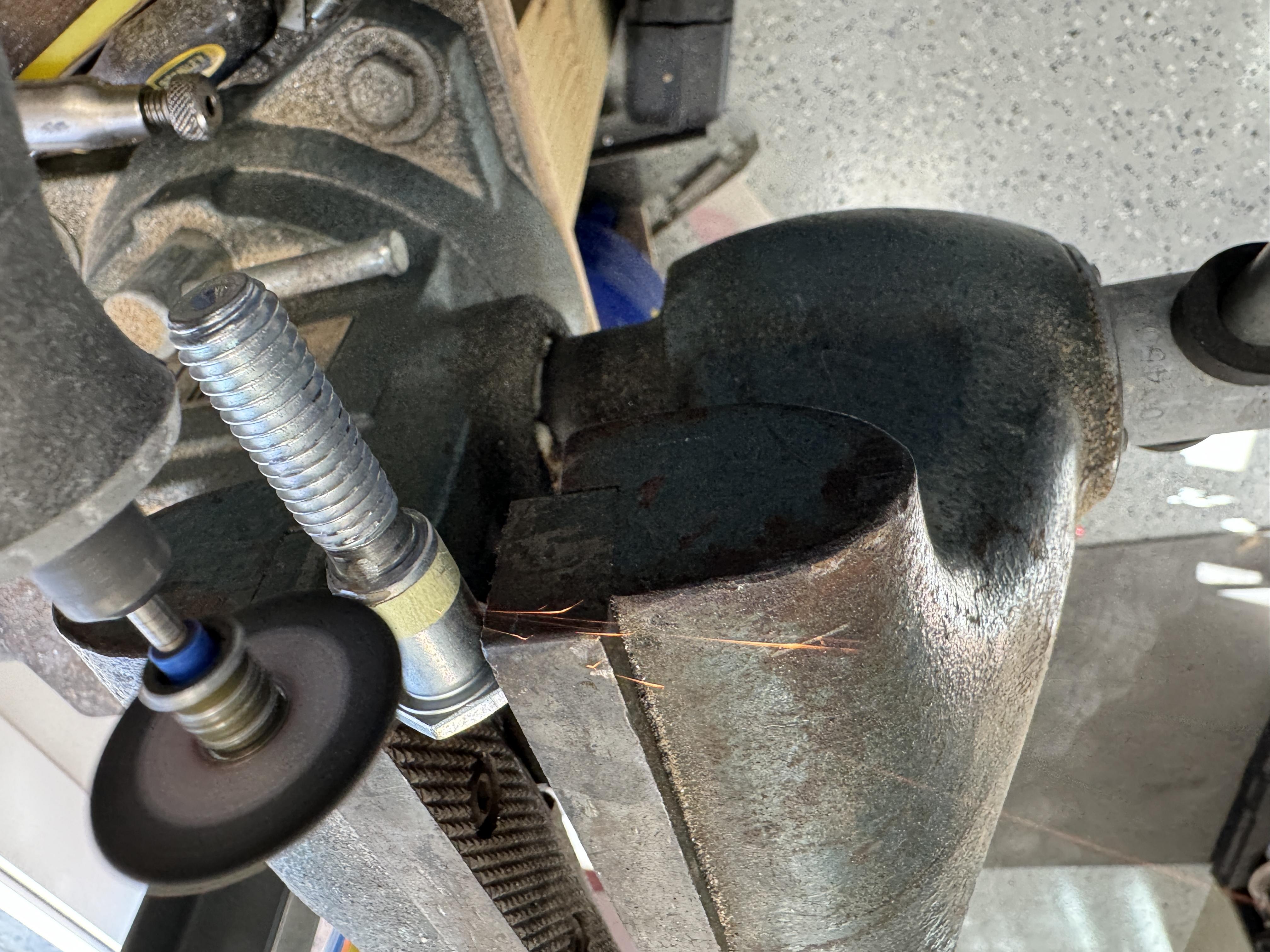
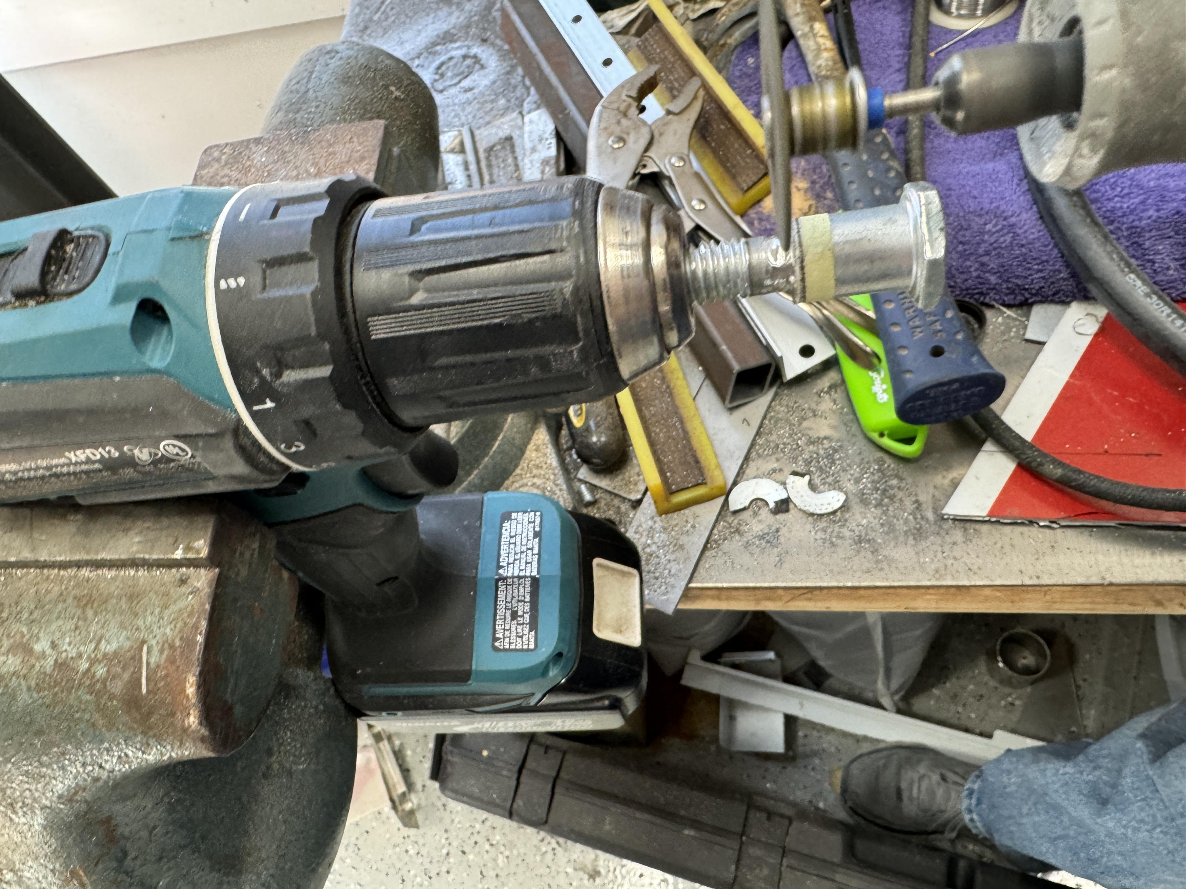
That was taking too long.... then I thought of making my own lathe.... here's my red-neck lathe and it worked very well. While the drill rotated the stud, the Dremel cut wheel made a clean cut.
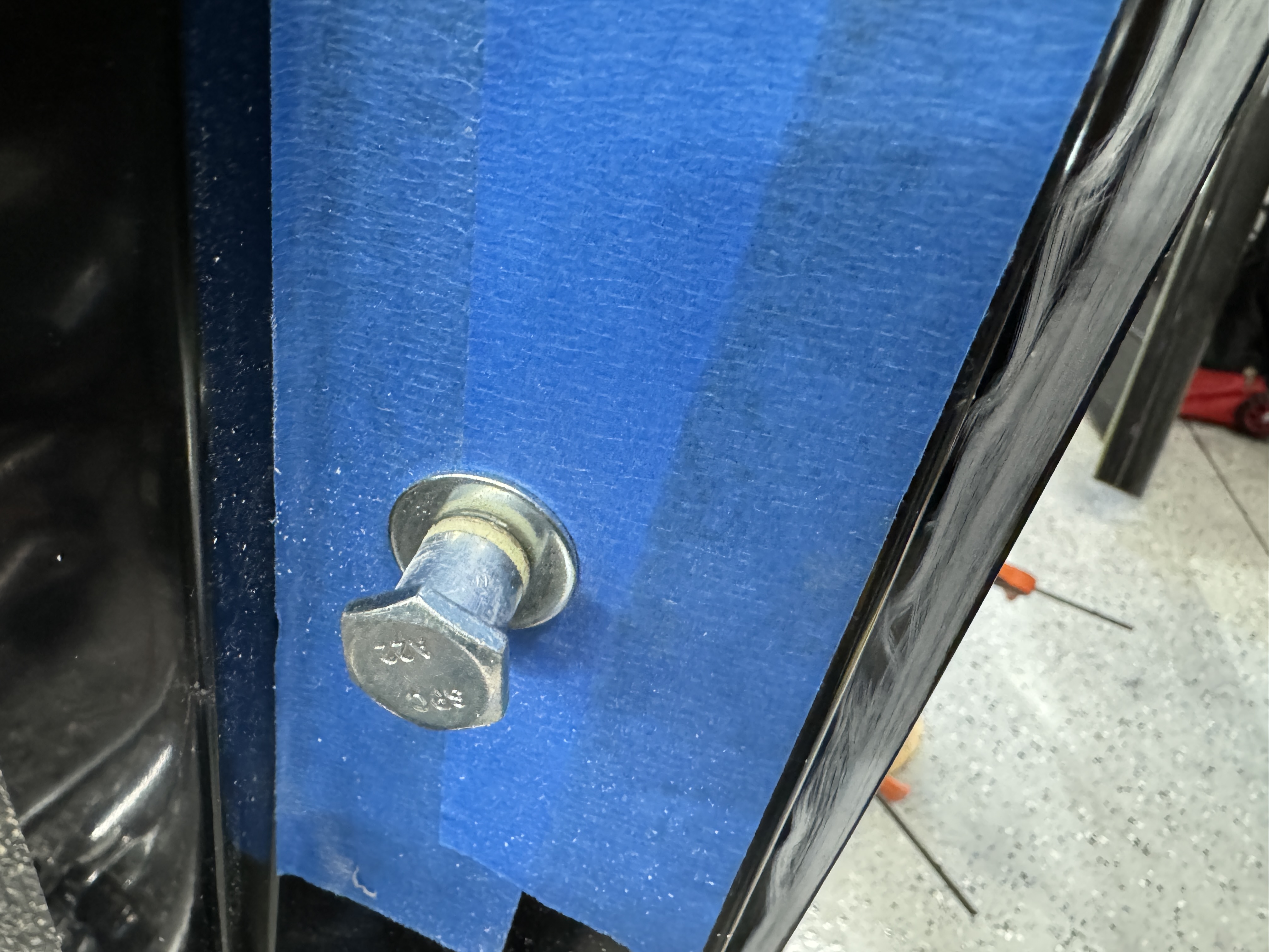
Then I added a this SS washer and mounted the stud
Feeling good and thinking I was now complete.... the third issue was discovered. Since the stud was too long.... That meant the door gap to the cab was too small. Which meant the three bolt heads (that held the internal door frame and latch in place) now hit the cab. To solve this problem, I removed the hex head bolts and installed 3 SS black button hex head bolts. I also went ahead and changed the passenger door latch bolts so all matched.
I believe "LEW" had the same issue on his truck.... but not sure if it was also the Driver's door?
That's it for my update today. I didn't get nearly the work done I was hoping for. I did get the door outside handles configured though.
Today will be a short workday for me.... we're going out of town to visit some friends and I'll be back in the shop next week. Today, I'll focus on door window installation.
Thanks Mark
-
02-16-2024, 07:17 PM
#197
Senior Member

https://edgemansgtm.weebly.com/rear-...ody-stuff.html
I have attached my build thread. Your fuel filler cap with the key will separate from the main body of the flange if you don't have a ring on the back side to sandwich the pieces together. Its two pieces and just soldiered together.
-
02-17-2024, 09:40 AM
#198
Senior Member


Originally Posted by
Edgeman

https://edgemansgtm.weebly.com/rear-...ody-stuff.html
I have attached my build thread. Your fuel filler cap with the key will separate from the main body of the flange if you don't have a ring on the back side to sandwich the pieces together. Its two pieces and just soldiered together.
Thanks Doug.... I think my filler cap is different than yours, but I'll add the backer ring anyway since it will provide extra support and and help keep the fiberglass from flexing. I'm also going to add a backer plate for each door mirror.
Mark
-
Post Thanks / Like - 0 Thanks, 1 Likes
-
02-21-2024, 11:53 AM
#199
Senior Member

Today.... I needed to do something different...
I connected the battery, some gauges and then cranked the engine without gas connected to build oil pressure.
Once that was done, I ran fuel through the gas line at the engine to clear any debris and then connected the line to the fuel rail.
Fire extinguisher in hand, I cranked and woo-hoo, it started first try !! Sounded pretty good too I might add.
Watch quick video.
And, I didn't need the fire extinguisher!
Mark
-
Post Thanks / Like - 0 Thanks, 1 Likes
-
02-22-2024, 12:40 PM
#200
Senior Member


 Thanks:
  Likes:


 Reply With Quote


 .
. 
