Visit our community sponsor

Thanks:
2

Likes:
12
-
Subaru SSM to Can-Bus Convertor DIY
Creating a thread for my SSM to Can-bus convertor. It will be driven by an arduino Uno and utilize an MC33660 For the K-Line SSM communications and an MC2515 for Can-Bus. I will also be utilizing some of the extra channel on the arduino to bring in the blinkers, high-beam, and oil pressure and serve them up to a digital dash over OBD-II adapter.
My first disclaimer is that while I work with automation and code for a living, It's of a much different nature than what I'm taking on here. I'm not an electrical engineer and have no background in electronics, so be wary of anything I'm doing until I've posted final results that it is all working. If you see me doing something totally wrong, please let me know and save me some heartache.
I'm basing my build off of a youtube video that appears to have accomplished almost exactly what I'm hoping to do:
https://www.youtube.com/watch?v=vfkFrv7F5E4
And what appears to be the associated GitHub project:
https://github.com/matprophet/subduino
However neither the video nor the GitHub site explain the hardware side of things.
Based on the libraries used in the code it appears that a MC33660 is being used the SSM communications. They seem pretty hard to find but are available on mouser (https://www.mouser.com/ProductDetail...JnL4W0Y%2Fnssf) however they are in a SIOC form factor and won't fit on an Arduino, so I ordered a SIOC to DIP adapter (https://smile.amazon.com/gp/product/...?ie=UTF8&psc=1) that I hope will get me connected.
The code also uses an MC2515 for CANbus communications which seems to be very common. I'm using a standalone card rather than a shield because it is easier to breadboard with.
Today I wired up the MC2515 to the Arduino according to the upper half of this diagram:

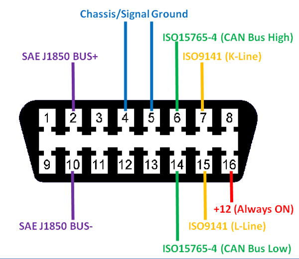
from here (https://www.electronicshub.org/ardui...-bus-tutorial/) and then hooked up a OBD-II port with the CanHi from the MC2515 connected to pin 6 and CanLo connected to pin 14. I also supplied 12+ from a power supply to pin 16, and then connected ground from my power supply and the arduino (which is powered from USB) together and put them on pins 4 and 5.

I utilized the code from the GitHub above to try and simulate OBD-II CANbus data and read it with a ELM adapter on my phone, but I was never able to pickup any data. I'm not sure if it is a code issue, a wiring issue, or both. I'm way above my head here, but hopefully can make some progress soon.
Last edited by Ajzride; 11-14-2019 at 11:15 PM.
 Posting Permissions
- You may not post new threads
- You may not post replies
- You may not post attachments
- You may not edit your posts
-
Forum Rules

Visit our community sponsor


 Thanks:
  Likes:


 Reply With Quote