I didn't keep that part. I can't see the picture of the end cap you were referring to. Did you figure it out?
Visit our community sponsor
I didn't keep that part. I can't see the picture of the end cap you were referring to. Did you figure it out?
Frank
818 chassis #181 powered by a '93 VW VR6 Turbo GT3582R
Go-karted Aug 5, 2016 - Then May 19+21, 2017
Tracked May 27/July 26, 2017
Build time before being driveable on Sep 27, 2019: over 6000h
Build Completed Winter 2021
The small ring left from where you cut I wouldn't worry about. It shouldn't see any large forces or stress. If it makes you happy you could fill the ring with epoxy and sand it smooth.
The end clip looks in need of replacement. When I removed mine I was able to keep it intact. Then hook the clip back in the endcap hole and twist the endcap to draw the clip back around.
I'll remove that small ring, then.
That's what I sort of understood with the end cap. Maybe it's (clip) gonna twist again in. Otherwise I'll replace it or find another way to keep the end cap there.
BTW, what is the end cap's purpose now that only grease and no pressure is in the housing?
Frank
818 chassis #181 powered by a '93 VW VR6 Turbo GT3582R
Go-karted Aug 5, 2016 - Then May 19+21, 2017
Tracked May 27/July 26, 2017
Build time before being driveable on Sep 27, 2019: over 6000h
Build Completed Winter 2021
I would think it would keep the center rod/rack/shaft centered and oriented to the pinion properly.
I thought of that too. But then I saw the hole inside the housing around the middle section is smaller than the housing itself, which helps keeping the rod aligned. And once the... I don't know how to call that, but that small metal part with a concave side, once this is pressed and torqued on the rod, can it then really move or not be aligned? Theories only, I don't know.
Best is to find a way to keep that end cap in, I agree. Will do.
Tnx for clarifying!
Next step: making that quill a once piece-no-movement piece.
Frank
818 chassis #181 powered by a '93 VW VR6 Turbo GT3582R
Go-karted Aug 5, 2016 - Then May 19+21, 2017
Tracked May 27/July 26, 2017
Build time before being driveable on Sep 27, 2019: over 6000h
Build Completed Winter 2021
That concave piece does work to keep everything aligned properly. The end cap in question is at the other end of the rack though, potential for movement with that distance. All still just my humble opinion though.
Good luck with getting that end cap re-attached.
Yeah that's quite possible!
Tnx for the info.
Frank
818 chassis #181 powered by a '93 VW VR6 Turbo GT3582R
Go-karted Aug 5, 2016 - Then May 19+21, 2017
Tracked May 27/July 26, 2017
Build time before being driveable on Sep 27, 2019: over 6000h
Build Completed Winter 2021
Ok so the play I have on the quill is not the same as metalmaker.
I cannot weld the bearing to the stem. I have to weld the 2 stems together.
QuillPlay1.jpg
If I keep the valve or that thing with multiple rings on it and weld it to the stem, it won't be hard enough as only one small dent will keep everything in place.
QuillPlay2.jpg
It's going to the TIG welder this week.
Frank
818 chassis #181 powered by a '93 VW VR6 Turbo GT3582R
Go-karted Aug 5, 2016 - Then May 19+21, 2017
Tracked May 27/July 26, 2017
Build time before being driveable on Sep 27, 2019: over 6000h
Build Completed Winter 2021
Frank, yes, weld the 2 stems together. You can remove the rotary valve completely.
Have you seen the 818 Registry on Google Maps?? https://www.google.com/maps/ms?msid=...a=0&dg=feature
Want your 818 added to the Registry? https://docs.google.com/forms/d/1zmF...rNCY4/viewform
Yes? I thought the bottom ring (metal similar to a bearing) of the valve was helping the stem stay in line, to align it.
I'll trash the valve then, the least number of parts I run on the car, the better.
Frank
818 chassis #181 powered by a '93 VW VR6 Turbo GT3582R
Go-karted Aug 5, 2016 - Then May 19+21, 2017
Tracked May 27/July 26, 2017
Build time before being driveable on Sep 27, 2019: over 6000h
Build Completed Winter 2021
Why not tap the PS fittings for Zerk fittings and use this access to periodically lube the pinion? Also why not leave seal in, loop left to right and fill both sides with ATF? This would in effect dampen steering feedback. If too much dampening use lighter oil or if more dampening is needed a valve could be installed in the loop line. No disassembly of rack required.
I planed on filling the small tube (where the quill goes in, in my video) with thick bearing grease.
Frank
818 chassis #181 powered by a '93 VW VR6 Turbo GT3582R
Go-karted Aug 5, 2016 - Then May 19+21, 2017
Tracked May 27/July 26, 2017
Build time before being driveable on Sep 27, 2019: over 6000h
Build Completed Winter 2021
If you want that piece of mind, I say do it. I just lubed mine with thick bearing grease, because IMO the rack isn't subjected to high heat or pressure. I think if you keep the dust out, and lube it decently the first time, you'll likely not need to touch it for years.
Have you seen the 818 Registry on Google Maps?? https://www.google.com/maps/ms?msid=...a=0&dg=feature
Want your 818 added to the Registry? https://docs.google.com/forms/d/1zmF...rNCY4/viewform
My quill (or whatever you call that thing) once welded:
QuillPlay3.jpg
Frank
818 chassis #181 powered by a '93 VW VR6 Turbo GT3582R
Go-karted Aug 5, 2016 - Then May 19+21, 2017
Tracked May 27/July 26, 2017
Build time before being driveable on Sep 27, 2019: over 6000h
Build Completed Winter 2021
Yes you do!!!!!!
If you don't, the rod will have a play on the end cap's side. And a big one for a steering rack. It may even be so dangerous on the road and in a curve that something could break and you crash. There should be no play on a steering rack. This metal stopper aligns the rod and keeps it in place so that it has no up/down play.
Use this clip just in case it may keep the metal stopper from sliding too far on one end.
Attachment 27630
And use the end cap to prevent the stopper from coming out. Besides, the stopper helps fitting the end cap properly as it sits on it.
Attachment 27731
Frank
818 chassis #181 powered by a '93 VW VR6 Turbo GT3582R
Go-karted Aug 5, 2016 - Then May 19+21, 2017
Tracked May 27/July 26, 2017
Build time before being driveable on Sep 27, 2019: over 6000h
Build Completed Winter 2021
For those with a late model pinion with integral upper ball bearing (I have a 2006 WRX rack), you can disassemble this bearing before welding, and then re-assemble it afterwords to protect it from heat damage:
DSC_0996.jpg
First... Gently push the plastic ball cage out from behind with a small screwdriver...
DSC_0983.jpg
Next... While holding the shaft horizontally, wiggle the bearing a little until all the balls fall to the bottom of the race...
DSC_0984.jpg
With all of the balls at the bottom, lift up on the shaft and the bearing will fall apart...
DSC_0985.jpg
After welding, reassemble the bearing by loading all the balls into the bottom of the race, then insert the shaft and press it against the balls in the race while tilting the shaft to vertical. Then spread the balls evenly around the race and the bearing will no longer fall apart. Snap the plastic cage back into the bearing and you are done.
Good Luck... Jeff
(2002 WRX donor steering)
Just in case anyone wants to retain the sets of valves...I cut into mine with an angle grinder and had a friend tig weld the upper shaft, lower shaft, and valve-body(might not be the right term....electrical guy here) together.
Keeping the valves because I feel like they might help support the steering shaft. maybe is wasn't necessary.
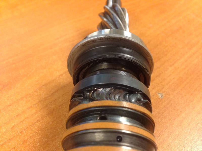
I have a 2002 wagon donor. I depowered the steering rack by turning down the piston, but still wanted to lock the slop out of the pinion shaft.
When I took it apart, I saw that there are flats on the input side of the shaft, and flats that the shaft fits into on the output side. I measured them and there is .030" slop, ie the output side is wider than the input side. So, the input can turn a little before the output turns, and that is when it unports the holes that send hydraulic pressure to the rack.
It was pretty easy to cut a couple of .015" shims to put between the flats on input and output to stop the slop. No welding necessary.
Here is a picture of the shims required. I cut them from an old feeler gage rather than ordering stock.
shims.jpg
Here is an end-on view of the shafts, the input is on the top, and you can see the flats, and how they fit into the output shaft.
end view steering.jpg
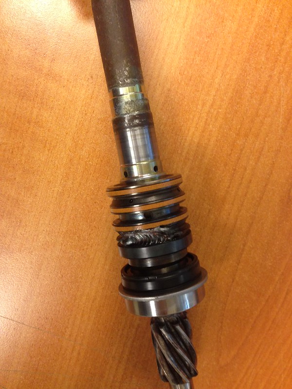
The next view shows how the shafts go together. I have one shim on top of the input shaft, and the other (hard to see) inside the end of the output shaft, so I can slide the two back together.
flats fitting together.jpg
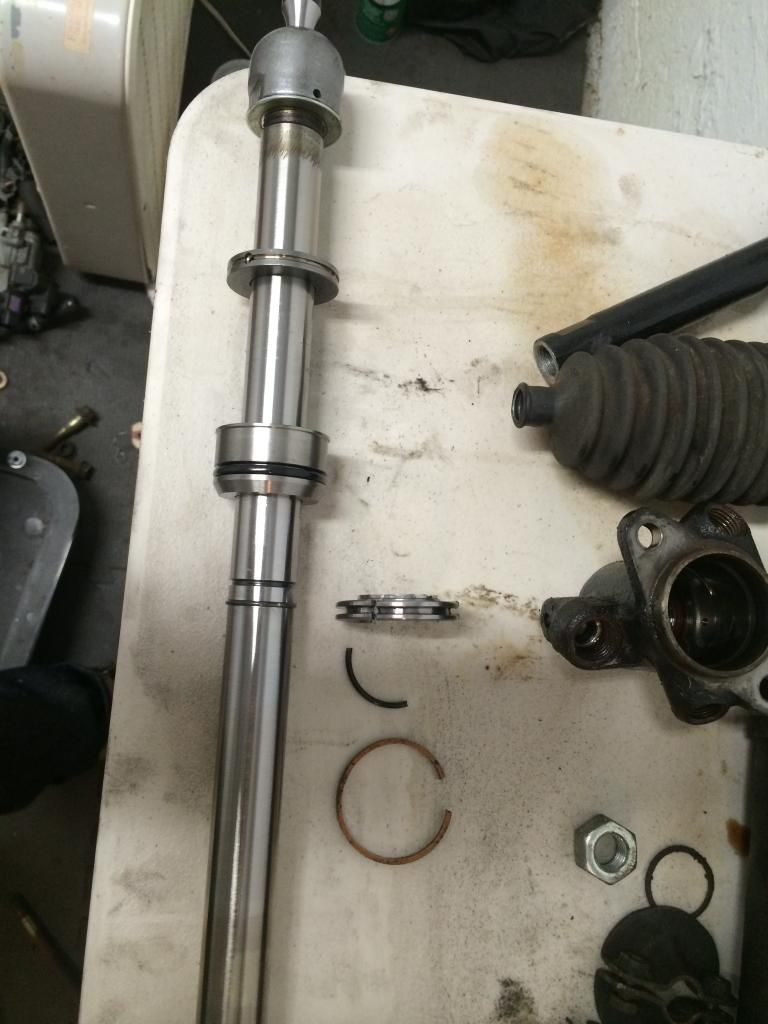
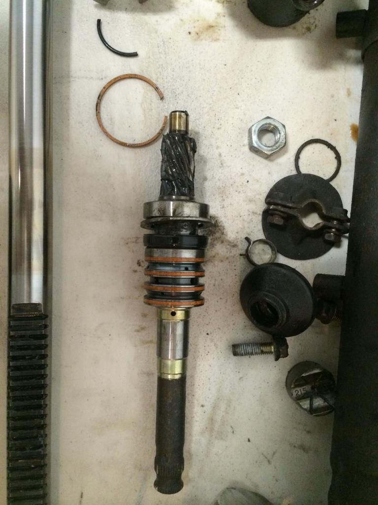
Finally, the shaft is back together, and ready to reinsert into the rack.
back together.jpg
Since the shim stock is fairly hard, and the shims fill the entire space, I think this will last a long time. When I clamp the pinion gear in a vise, and turn the spine end, there is zero slop.
Good luck! John
Nice post nuisance, there goes another way to get that play off of the steering rack.
Frank
818 chassis #181 powered by a '93 VW VR6 Turbo GT3582R
Go-karted Aug 5, 2016 - Then May 19+21, 2017
Tracked May 27/July 26, 2017
Build time before being driveable on Sep 27, 2019: over 6000h
Build Completed Winter 2021
I am going to start a depowering the rack gig. I have done about 10-15 other car types and 5 818 conversions and now I figure I will offer the service.
The drop off fee: $200
Mailing in fee of: $240 ( you pay to mail it in, but I do work and mail it back to you, and mailing fee is included in price)
Includes: teardown and seal removal, cleaning, pinion and line end welding, blasting, painting of line ends re-assembly with
High temp greese, and new boot ties.
Any other parts that are needed ( bushings, boots, inner parts etc, will be added to the bill with no additional labor
PayPal or cash only
Pm if your interested.
image.jpgimage.jpgimage.jpgimage.jpg
818S frame #13 Jdm version 8 ej207
Quick question for you guys-
How does the inner portion of the tie-rod end come off?
The bit under the boot, attached to the actual main steering rack rod, not the portion that has the lock nut out towards the ball joint.
Guitarist - I think you are talking about the portion that is held on by the lock washer. You basically just have to unbend the lock washer (it is crushed down on opposite sides around the inner tie rod and then use a big wrench to unscrew the inner tie rod. The steering rack should be otherwise intact when you do this in order to keep it from spinning.
You should order a new lock washer in order to reinstall. They cost less than $1, but you will have to order from Subaru based on what I could find. Part 34188A in this diagram. http://www.newenglandsubaruparts.com...11-347-02.html
Thanks Bill,
Yes, I was talking about removing 34906.
I'll have a look in that area- I was working from the other end, and put the pinion back in to lock it from rotating.
The good news is you should only need to remove the driver's side inner tie rod. This will allow you to slip the actual rack out the passenger side after removing the pinion and the guide/sleeve (which is behind the giant nut on the front of the rack - i put this in a vice and turned the entire rack to get it loose since i didn't have a wrench big enough for it and I didn't want to tear it up with a pipe wrench)
Yep, I see how that'd work now.
Already had the rest disassembled! Ah well, back together a little, then back apart.
Interesting, I used subaru part number 34112AA000 to replace the lock washer, I wonder if those 34XXX part numbers are specific to that website?
34XXX is a lookup to the list section. You can see the full part number on the "add to cart" button.
exactly - those are just used so the part numbers on the diagrams aren't completely crazy and cross referencing to the order list is easier. some of them are a bit of a "where's waldo" as it is. thank god for "Ctrl + F"
Is there a "best fit" year and model of rack? I'm building without a donor so I can order any rack......I'm also considering having a true manual quick ratio rack made but I'll need the correct power rack dimensions to copy.
Thanks
Whoops just saw the Best Fit thread. But still interested if anyone has other thoughts....
Last edited by Sgt.Gator; 09-08-2014 at 12:57 PM.
"Good Judgement comes from Experience. Experience comes from Bad Judgement"
Owner: Colonel Red Racing
eBAy Store: http://stores.ebay.com/colonelredracing
818R ICSCC SPM
Palatov DP4 - ICSCC Sports Racer
Got my seal cut off. Since my rack was Koyo like some others here, thought I'd post pictures.
The larger piece DOES move on mine.
Seal cut off, other sliding piece left on. It bottoms out on the body just behind the part that uses a spanner wrench to remove.
Haven't welded this up yet.
Anyone know what size bolt/pitch I need to plug all the hydraulic lines with? I'd like to plug them instead of looping them (now that I removed the plunger), and I don't have a welder.
Unless my bolt bin is wrong, it looks like an M12 diameter but the pitch is finer than 1.25. There is also one that's even bigger than an M14... no clue what to put in that one. The rack is from an 06WRX.
Also, does anyone know the proper way to adjust the rack tension mechanism? The FSM doesn't seem to cover that. It's the bolt with a giant jam nut, and on the end of the bolt (inside the rack housing), there is a spring and then a little piece that presses up against the rack and loads it up.
Last edited by Hindsight; 12-06-2014 at 07:10 PM.
I am not road tested and proven yet, but I was able to weld mine up with just a plain ol' boring flux core wire feed welder. I was not able to reinstall the valve body (?) - the part with the 3 or 4 little orange seals, but that does not appear to be necessary. Steering feels smooth and solid in super official garage testing (vroom vroom noises optional).
FYI Metalmaker will weld your pinion for you. He did an awesome job on mine.
They just pulled apart when I took the housing apart.
John Huft -- #154 R
Good call, I was doing the same trying to grind my welds down to fit the valve seal, in which I ended up getting to fit. I then reinstalled everything and it worked well (no shaft play). Thankfully I saw this because I realized the shaft rides on the two bearings (the one thats pressed on and the one thats at the top of the shaft near where the steering knuckle attaches) and not the valve seal at all. In fact without the valve see I also found this made the steering even smoother and I also was able to go back in and weld it up really well knowing the extra space I had to place these welds.
Thanks again!
Got my steering rack finished this weekend. Thanks for all the help on this thread!
I decided to keep it brushed steel with high temp clear coat. I welded all the ports, even the aluminum ones. I ground off some of the channels. If i had more time, I would have shaved off all the channels.
Now if I could just get that fancy steering rack bushing from Zero Decibel Motorsports soon
DSC04381.JPG
DSC04387.JPG
DSC04388.JPG
DSC04389.JPG
DSC04390.JPG
DSC04400.JPG
DSC04405.JPG
DSC04407.JPG
Resurrecting this thread as I attempt to de-power my 06 steering rack. I too am having an issue getting off the recessed nut that goes over the pinion shaft. I tried a drift and hammer and it wouldn't budge, only gouged the nut a bit before I stopped making a mess of it. May try and make a spanner, but should it be that hard to get loose?