FormaCars

Visit our community sponsor

Thanks Thanks:  0
Likes Likes:  0
Results 1 to 24 of 24

Thread: Electrical Switch Questions

  1. #1
    Papa's Avatar
    Join Date
    Dec 2016
    Location
    Mexico, MO
    Posts
    5,619
    Post Thanks / Like

    Electrical Switch Questions

    I have my gauges wired and the dash zip tied in place and now I have to decide where to mount the turn signal switch, hi/lo beam switch, and hazard switch. I'm thinking the hazard and hi/low beam switches will get mounted in a dash brace near the left edge of the dash. The turn signal switch should go in the dash, but I'm not sure how the padded dash will handle drilling additional holes. I don't want to shred the padding around the hole with a drill bit. Any tips?

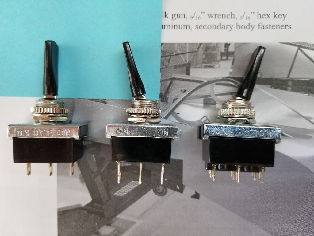
    I assume the switch on the left is the turn signal (3-way), and the one in the middle is for the hi/lo beam, but I'm not sure about the switch on the right with the six pins. I assume it's the hazard flasher switch?


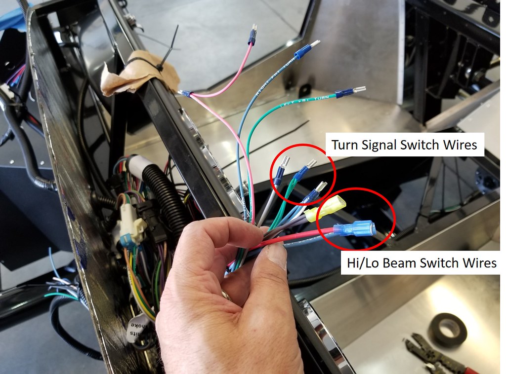
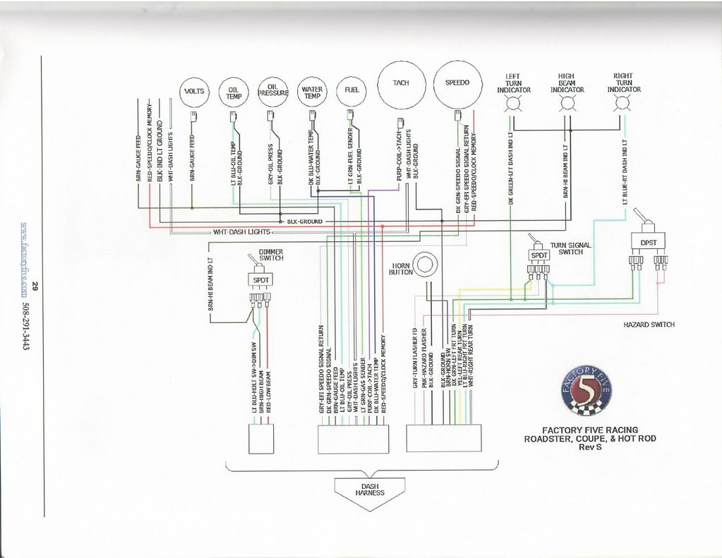
    Finally, any help with where to connect the wires would be great. There are two sets of turn signal wires (a single left and right and a pair of three-wire bundles for left and right). Which ones go to which switch? The high/lo beam wires are simple, and I assume a ground goes to the center pin on the switch.


    Thanks,
    Dave
    My Build Thread: http://thefactoryfiveforum.com/showt...ter-Build-9754
    (Most viewed Roadster build thread on this forum!)

    Delivered: 6/17/2017
    First Start: 12/30/2017
    Completed: 12/7/2019
    Legal: 1/30/2020

    Member of the Mile-Hi Cobra Club
    Dave's Cobra YouTube Channel: https://www.youtube.com/channel/UCbk...npK1UZHj4R-bYQ
    Agora 1:8 Scale Cobra Build: https://thefactoryfiveforum.com/show...l-Build-Thread

  2. #2
    Senior Member Big Blocker's Avatar
    Join Date
    Feb 2011
    Location
    Lost Wages, Nevada
    Posts
    634
    Post Thanks / Like
    NOOOOOOO . . . NO grounds at the Hi/Lo switch. Center pin is for the feed to the switch (inbound) from your headlight switch, other two pins are Hi and Lo (outbound).

    FWIW, most switches we use in our cars are NOT grounded, they simply provide power to whatever the switch is designated for - unless you're using them for relay control.

    You are correct in your statement about what switch is what. TS switch is power in (in from flasher), other two pins are left and right (outbound).
    Other 6 pin switch is for hazards.

    I'm one of the 10 . . . Ha-Ha-Ha.

    Doc
    Last edited by Big Blocker; 09-03-2017 at 09:38 PM.
    FFR3712K (MKII) in Lost Wages Nevada.
    5.0 w/tubular GT-40 EFI, E303 cam, Custom 4 into 4 headers, T5, 3-Link 3.73 rear. Full F5 tubular suspension. Drop Butt mod, Dash forward mod, custom foot box air vents, custom turn signal system. 13" PBR brakes, Fiero E-Brake mod, Flaming River 18:1 rack w/ F5 bump steer kit on Breeze bushings. 17" Chrome Cobra "R's" w/ 275 fronts and 315 rears. MKIV seats. FORD Royal Blue w/ Arctic White stripes.

  3. #3
    Papa's Avatar
    Join Date
    Dec 2016
    Location
    Mexico, MO
    Posts
    5,619
    Post Thanks / Like
    Thanks, Doc. So, with that I've narrowed down the following:


    There are the two single front left/right turn signal wires and the hazard (red pigtail). What do I do with them? Do they go to the six pin switch?
    My Build Thread: http://thefactoryfiveforum.com/showt...ter-Build-9754
    (Most viewed Roadster build thread on this forum!)

    Delivered: 6/17/2017
    First Start: 12/30/2017
    Completed: 12/7/2019
    Legal: 1/30/2020

    Member of the Mile-Hi Cobra Club
    Dave's Cobra YouTube Channel: https://www.youtube.com/channel/UCbk...npK1UZHj4R-bYQ
    Agora 1:8 Scale Cobra Build: https://thefactoryfiveforum.com/show...l-Build-Thread

  4. #4
    Senior Member CraigS's Avatar
    Join Date
    Feb 2011
    Location
    Blacksburg, Va
    Posts
    4,759
    Post Thanks / Like
    When I added a couple of switches I started drilling w/ a regular bit of about 1/8 inch-slowly. Then I did the rest w/ a step drill-slowly. The step has the advantage of not grabbing the aluminum and pulling the drill toward the dash. It also drilled the aluminum while not destroying the leatherette. I was actually surprised how easy it was to do.
    FFR MkII, 408W, Tremec TKO 500, 2015 IRS, DA QA1s, Forte front bar, APE hardtop.

  5. #5
    Papa's Avatar
    Join Date
    Dec 2016
    Location
    Mexico, MO
    Posts
    5,619
    Post Thanks / Like
    Quote Originally Posted by CraigS View Post
    When I added a couple of switches I started drilling w/ a regular bit of about 1/8 inch-slowly. Then I did the rest w/ a step drill-slowly. The step has the advantage of not grabbing the aluminum and pulling the drill toward the dash. It also drilled the aluminum while not destroying the leatherette. I was actually surprised how easy it was to do.
    Thanks for the tip on the step bit. The padded FFR dash has the advantage of having the padding fused to the plastic backing, so it may not get wrapped around the bit. I'll start with a small bit and see how it behaves. If that doesn't work, I guess it'll be time to bring out the razor knife.
    My Build Thread: http://thefactoryfiveforum.com/showt...ter-Build-9754
    (Most viewed Roadster build thread on this forum!)

    Delivered: 6/17/2017
    First Start: 12/30/2017
    Completed: 12/7/2019
    Legal: 1/30/2020

    Member of the Mile-Hi Cobra Club
    Dave's Cobra YouTube Channel: https://www.youtube.com/channel/UCbk...npK1UZHj4R-bYQ
    Agora 1:8 Scale Cobra Build: https://thefactoryfiveforum.com/show...l-Build-Thread

  6. #6
    Senior Member weendoggy's Avatar
    Join Date
    Feb 2011
    Location
    Aptos, CA
    Posts
    406
    Post Thanks / Like
    Quote Originally Posted by Papa View Post


    There are the two single front left/right turn signal wires and the hazard (red pigtail). What do I do with them? Do they go to the six pin switch?
    How are the two single L/R wires connected to the existing harness? Are they for your L/R signal light indicator? They might connect back to the ones circled in the harness. If so, that would most likely be your indicator leads. However, they might go to the T/S switch to control that part. It depends on how the harness is wired.

    Your 4-way toggle will be wired with the flasher lead (coming in) connected to BOTH middle teminals and the L/R will be connected to one end of the toggle. Both respectively on L/R side but it doesn't matter which side for each. This will leave nothing on the other end of the toggle (two terminals empty). You'll have to see how you wire the toggle to position it correctly. Otherwise it will be ON in the down position. All you need to do then is move the L/R wires to the other end. I could help more but need wiring diagram info first.
    I'm just a victim of a thousand physic wars!
    www.weendoggy.com/cobra.htm

  7. #7
    Papa's Avatar
    Join Date
    Dec 2016
    Location
    Mexico, MO
    Posts
    5,619
    Post Thanks / Like
    Quote Originally Posted by weendoggy View Post
    How are the two single L/R wires connected to the existing harness? Are they for your L/R signal light indicator? They might connect back to the ones circled in the harness. If so, that would most likely be your indicator leads. However, they might go to the T/S switch to control that part. It depends on how the harness is wired.

    Your 4-way toggle will be wired with the flasher lead (coming in) connected to BOTH middle teminals and the L/R will be connected to one end of the toggle. Both respectively on L/R side but it doesn't matter which side for each. This will leave nothing on the other end of the toggle (two terminals empty). You'll have to see how you wire the toggle to position it correctly. Otherwise it will be ON in the down position. All you need to do then is move the L/R wires to the other end. I could help more but need wiring diagram info first.
    Thanks, weendoggy. The harness has another set of indicator light wires that I connected to the wires on the speedo gauge. That was clear in the Ron Francis wiring manual. the three sets of wires I've shown in my picture are what is left to go to the switches. The good thing is they are sort of grouped in three different lengths, so with Doc's info above I was able to figure out the hi/lo beam and turn signal switch connections. I believe your info on the six-pin switch will complete the hazard switch wiring. If I'm following you, the two red (pigtail) connectors will go to the two center pins and then the remaining two wires will go to either side of the switch leaving one side (two pins) empty?

    Dave
    My Build Thread: http://thefactoryfiveforum.com/showt...ter-Build-9754
    (Most viewed Roadster build thread on this forum!)

    Delivered: 6/17/2017
    First Start: 12/30/2017
    Completed: 12/7/2019
    Legal: 1/30/2020

    Member of the Mile-Hi Cobra Club
    Dave's Cobra YouTube Channel: https://www.youtube.com/channel/UCbk...npK1UZHj4R-bYQ
    Agora 1:8 Scale Cobra Build: https://thefactoryfiveforum.com/show...l-Build-Thread

  8. #8
    Senior Member weendoggy's Avatar
    Join Date
    Feb 2011
    Location
    Aptos, CA
    Posts
    406
    Post Thanks / Like
    If you're talking about the top three wires in your picture, with the Red (light color) being the lead from the 4-way flasher, then yes, that is correct.
    I'm just a victim of a thousand physic wars!
    www.weendoggy.com/cobra.htm

  9. #9
    Papa's Avatar
    Join Date
    Dec 2016
    Location
    Mexico, MO
    Posts
    5,619
    Post Thanks / Like
    Cool. Here is what I have:

    Hi/Low Beam switch has blue headlight dim wire as feed and red low-beam and brown high-beam as the two outputs:


    The Turn signal switch has the gray flasher wire as the feed and the two three-wire bundles (front/rear turn signal) as the outputs:


    And the hazard switch has the red pigtail from the flasher as the feed and the two remaining wires as the output on one side of the switch:


    Now I just need to pay attention to the orientation when mounting the switches to get the correct switch positions.
    My Build Thread: http://thefactoryfiveforum.com/showt...ter-Build-9754
    (Most viewed Roadster build thread on this forum!)

    Delivered: 6/17/2017
    First Start: 12/30/2017
    Completed: 12/7/2019
    Legal: 1/30/2020

    Member of the Mile-Hi Cobra Club
    Dave's Cobra YouTube Channel: https://www.youtube.com/channel/UCbk...npK1UZHj4R-bYQ
    Agora 1:8 Scale Cobra Build: https://thefactoryfiveforum.com/show...l-Build-Thread

  10. #10
    Senior Member Big Blocker's Avatar
    Join Date
    Feb 2011
    Location
    Lost Wages, Nevada
    Posts
    634
    Post Thanks / Like
    If you get the switch mounted up-side-down, just re position the outer wire on the switch. The center wire(s) are 99% of the time the feed TO the switch where the outer wire(s) are the outbound circuit to the device you are powering.
    Everything looks correct as near as I can tell from your pics. Test everything before hooking up the car battery, use a 12v lattern battery or low amperage battery charger. Don't want to let any of the "smoke" out of your wire loom.

    Doc
    FFR3712K (MKII) in Lost Wages Nevada.
    5.0 w/tubular GT-40 EFI, E303 cam, Custom 4 into 4 headers, T5, 3-Link 3.73 rear. Full F5 tubular suspension. Drop Butt mod, Dash forward mod, custom foot box air vents, custom turn signal system. 13" PBR brakes, Fiero E-Brake mod, Flaming River 18:1 rack w/ F5 bump steer kit on Breeze bushings. 17" Chrome Cobra "R's" w/ 275 fronts and 315 rears. MKIV seats. FORD Royal Blue w/ Arctic White stripes.

  11. #11
    Senior Member weendoggy's Avatar
    Join Date
    Feb 2011
    Location
    Aptos, CA
    Posts
    406
    Post Thanks / Like
    I'm going to ask, is the H/L toggle handling ALL the load to the lights? If so, you're going to have issues with the toggle overheating and possibly burning up. The toggle is not really strong enough to sustain the load. jmo
    I'm just a victim of a thousand physic wars!
    www.weendoggy.com/cobra.htm

  12. #12
    Papa's Avatar
    Join Date
    Dec 2016
    Location
    Mexico, MO
    Posts
    5,619
    Post Thanks / Like
    Quote Originally Posted by weendoggy View Post
    I'm going to ask, is the H/L toggle handling ALL the load to the lights? If so, you're going to have issues with the toggle overheating and possibly burning up. The toggle is not really strong enough to sustain the load. jmo
    That I don't know. I'll check the wiring diagrams and see if they are relay protected.
    My Build Thread: http://thefactoryfiveforum.com/showt...ter-Build-9754
    (Most viewed Roadster build thread on this forum!)

    Delivered: 6/17/2017
    First Start: 12/30/2017
    Completed: 12/7/2019
    Legal: 1/30/2020

    Member of the Mile-Hi Cobra Club
    Dave's Cobra YouTube Channel: https://www.youtube.com/channel/UCbk...npK1UZHj4R-bYQ
    Agora 1:8 Scale Cobra Build: https://thefactoryfiveforum.com/show...l-Build-Thread

  13. #13
    Papa's Avatar
    Join Date
    Dec 2016
    Location
    Mexico, MO
    Posts
    5,619
    Post Thanks / Like
    If I'd taken the time to study the wiring diagrams earlier, I may have answered my own questions on the switch wiring.


    However, the question about relays has me wondering. The only relays in the fuse block are for the horn, cooling fan, and fuel pump. The Headlight power comes through a 15 amp fuse on the main fuse block and into the headlight switch. The light blue wire (Hdlt Sw -> Dim Sw) comes from the headlight switch to the 6 amp toggle as the feed. Is there a relay inside the headlight switch?
    My Build Thread: http://thefactoryfiveforum.com/showt...ter-Build-9754
    (Most viewed Roadster build thread on this forum!)

    Delivered: 6/17/2017
    First Start: 12/30/2017
    Completed: 12/7/2019
    Legal: 1/30/2020

    Member of the Mile-Hi Cobra Club
    Dave's Cobra YouTube Channel: https://www.youtube.com/channel/UCbk...npK1UZHj4R-bYQ
    Agora 1:8 Scale Cobra Build: https://thefactoryfiveforum.com/show...l-Build-Thread

  14. #14
    Senior Member weendoggy's Avatar
    Join Date
    Feb 2011
    Location
    Aptos, CA
    Posts
    406
    Post Thanks / Like
    Most H/L switches have a built in circuit breaker. If it's a small cheap one, I doubt it has one unless its connected to it like some are. If you have nothing, you are definitely running ALL the power through the toggle (not a good idea). It's just too much of a load going through the toggle. If the H/L switch has a breaker, you'll be safe running low beam, but I'd be looking at the high beam circuit too. A lot depends on the rest of you diagram and how they have it wired. Looking at the one above, I'd be leery if the power from the H/L switch is going to the toggle and activating the high beams.

    Many autos have H/L connected via breakers in case you have a short. They will go off/on, off/on, etc. as the breaker cools etc. This is so you still have some sort of lights. However, new cars now have fuses which are OK as well. At least you know you have an issue. Bottom line is they have protection in the switch to compensate for voltage needed. I would put a relay in both low and high side to be safe. I don't trust toggles to carry loads. Even my "DRL" has a relay and it only uses two 194 bulbs.
    I'm just a victim of a thousand physic wars!
    www.weendoggy.com/cobra.htm

  15. #15
    Senior Member Itchief's Avatar
    Join Date
    Aug 2017
    Location
    Southern WV
    Posts
    376
    Post Thanks / Like
    Papa

    Did you give any thought to a floor mounted switch, I installed a floor mounted switch and like it. It reminds me of the 1960 era car.

    Rick

  16. #16
    Papa's Avatar
    Join Date
    Dec 2016
    Location
    Mexico, MO
    Posts
    5,619
    Post Thanks / Like
    Quote Originally Posted by Itchief View Post
    Papa

    Did you give any thought to a floor mounted switch, I installed a floor mounted switch and like it. It reminds me of the 1960 era car.

    Rick
    I've considered it (still considering it if I need to wire in a relay). I'm not sure about placement given the cramped foot box, but will look at it before making my final decision.
    Last edited by Papa; 09-04-2017 at 10:15 PM.
    My Build Thread: http://thefactoryfiveforum.com/showt...ter-Build-9754
    (Most viewed Roadster build thread on this forum!)

    Delivered: 6/17/2017
    First Start: 12/30/2017
    Completed: 12/7/2019
    Legal: 1/30/2020

    Member of the Mile-Hi Cobra Club
    Dave's Cobra YouTube Channel: https://www.youtube.com/channel/UCbk...npK1UZHj4R-bYQ
    Agora 1:8 Scale Cobra Build: https://thefactoryfiveforum.com/show...l-Build-Thread

  17. #17
    Senior Member Big Blocker's Avatar
    Join Date
    Feb 2011
    Location
    Lost Wages, Nevada
    Posts
    634
    Post Thanks / Like
    Look on the side of the switch and see if it has an amperage rating printed on it. If it's at least 10 amp rated, you'll be fine. Headlights on HIGH draw about 9 amps (assuming a 55w headlight running at 13.2 v).

    That being said, my personal choice is to run relays on everything drawing high amperage and let the [toggle] switches handle all with low (1 amp max) amperage activation. That is the original design of relays; low amp activation of a high amp load. Most relays are 30a capable with 200Ma draw to activate it.

    FWIW, I have Headlights, Horns, Fan and Starter (push button start) on relays.

    HTH

    Doc
    Last edited by Big Blocker; 09-04-2017 at 10:20 PM.
    FFR3712K (MKII) in Lost Wages Nevada.
    5.0 w/tubular GT-40 EFI, E303 cam, Custom 4 into 4 headers, T5, 3-Link 3.73 rear. Full F5 tubular suspension. Drop Butt mod, Dash forward mod, custom foot box air vents, custom turn signal system. 13" PBR brakes, Fiero E-Brake mod, Flaming River 18:1 rack w/ F5 bump steer kit on Breeze bushings. 17" Chrome Cobra "R's" w/ 275 fronts and 315 rears. MKIV seats. FORD Royal Blue w/ Arctic White stripes.

  18. #18
    Papa's Avatar
    Join Date
    Dec 2016
    Location
    Mexico, MO
    Posts
    5,619
    Post Thanks / Like
    I'm wondering how many builders wire the switch as the diagram above shows vs. using a relay. I'm sure a relay will be safer for the wiring, but is the kit design really that flawed? If I want to wire in a relay, will this design work?


    I like that the low beams would be on by default and that the high beams would be activated via the switch. I'd use a simple accessory switch instead of the one I have wired up now. Any errors in my diagram?

    Thanks,
    Dave
    My Build Thread: http://thefactoryfiveforum.com/showt...ter-Build-9754
    (Most viewed Roadster build thread on this forum!)

    Delivered: 6/17/2017
    First Start: 12/30/2017
    Completed: 12/7/2019
    Legal: 1/30/2020

    Member of the Mile-Hi Cobra Club
    Dave's Cobra YouTube Channel: https://www.youtube.com/channel/UCbk...npK1UZHj4R-bYQ
    Agora 1:8 Scale Cobra Build: https://thefactoryfiveforum.com/show...l-Build-Thread

  19. #19
    Senior Member Itchief's Avatar
    Join Date
    Aug 2017
    Location
    Southern WV
    Posts
    376
    Post Thanks / Like
    You will not need a relay as long as the switch can handle the load mark at breeze stocks one that should work

    IMO

    I'm not sure if a relay would be safer the circuit has a fuse to limit the current an as long as the wire, switches etc can handle the rated current adding is not going to improve safety.
    I wired my by the diagram
    Last edited by Itchief; 09-04-2017 at 10:39 PM.

  20. #20
    Senior Member Big Blocker's Avatar
    Join Date
    Feb 2011
    Location
    Lost Wages, Nevada
    Posts
    634
    Post Thanks / Like
    Papa,

    Yes, that's a good wiring design for your headlights . . . a failure will still leave you with lo-beams (baring a fuse problem). Plus, with a momentary switch wired into parallel with your pictured switch, you would have a "Flash-to-Pass" function.
    FFR3712K (MKII) in Lost Wages Nevada.
    5.0 w/tubular GT-40 EFI, E303 cam, Custom 4 into 4 headers, T5, 3-Link 3.73 rear. Full F5 tubular suspension. Drop Butt mod, Dash forward mod, custom foot box air vents, custom turn signal system. 13" PBR brakes, Fiero E-Brake mod, Flaming River 18:1 rack w/ F5 bump steer kit on Breeze bushings. 17" Chrome Cobra "R's" w/ 275 fronts and 315 rears. MKIV seats. FORD Royal Blue w/ Arctic White stripes.

  21. #21
    Papa's Avatar
    Join Date
    Dec 2016
    Location
    Mexico, MO
    Posts
    5,619
    Post Thanks / Like
    Quote Originally Posted by Big Blocker View Post
    Papa,

    Yes, that's a good wiring design for your headlights . . . a failure will still leave you with lo-beams (baring a fuse problem). Plus, with a momentary switch wired into parallel with your pictured switch, you would have a "Flash-to-Pass" function.
    Thanks, Doc. I appreciate the advice and your patience.

    Dave
    Last edited by Papa; 09-05-2017 at 05:56 PM.
    My Build Thread: http://thefactoryfiveforum.com/showt...ter-Build-9754
    (Most viewed Roadster build thread on this forum!)

    Delivered: 6/17/2017
    First Start: 12/30/2017
    Completed: 12/7/2019
    Legal: 1/30/2020

    Member of the Mile-Hi Cobra Club
    Dave's Cobra YouTube Channel: https://www.youtube.com/channel/UCbk...npK1UZHj4R-bYQ
    Agora 1:8 Scale Cobra Build: https://thefactoryfiveforum.com/show...l-Build-Thread

  22. #22
    Papa's Avatar
    Join Date
    Dec 2016
    Location
    Mexico, MO
    Posts
    5,619
    Post Thanks / Like
    I'm going to wire in the relay and I also ordered a floor mounted dimmer switch. I have some ideas about how to mount it that I'll be happy with, but if that doesn't work out it'll be back to the dash mount.
    My Build Thread: http://thefactoryfiveforum.com/showt...ter-Build-9754
    (Most viewed Roadster build thread on this forum!)

    Delivered: 6/17/2017
    First Start: 12/30/2017
    Completed: 12/7/2019
    Legal: 1/30/2020

    Member of the Mile-Hi Cobra Club
    Dave's Cobra YouTube Channel: https://www.youtube.com/channel/UCbk...npK1UZHj4R-bYQ
    Agora 1:8 Scale Cobra Build: https://thefactoryfiveforum.com/show...l-Build-Thread

  23. #23
    Senior Member
    Join Date
    Jul 2017
    Posts
    165
    Post Thanks / Like
    Quote Originally Posted by Papa View Post
    I'm going to wire in the relay and I also ordered a floor mounted dimmer switch. I have some ideas about how to mount it that I'll be happy with, but if that doesn't work out it'll be back to the dash mount.
    I mounted my floor dimmer switch up top of the footbox and hit it my toes.

  24. #24
    Papa's Avatar
    Join Date
    Dec 2016
    Location
    Mexico, MO
    Posts
    5,619
    Post Thanks / Like
    I decided to go ahead and use a floor mounted dimmer switch. Here is a link to the post in my build thread that shows the bracket I made for it.

    http://thefactoryfiveforum.com/showt...l=1#post293666
    My Build Thread: http://thefactoryfiveforum.com/showt...ter-Build-9754
    (Most viewed Roadster build thread on this forum!)

    Delivered: 6/17/2017
    First Start: 12/30/2017
    Completed: 12/7/2019
    Legal: 1/30/2020

    Member of the Mile-Hi Cobra Club
    Dave's Cobra YouTube Channel: https://www.youtube.com/channel/UCbk...npK1UZHj4R-bYQ
    Agora 1:8 Scale Cobra Build: https://thefactoryfiveforum.com/show...l-Build-Thread

Posting Permissions

  • You may not post new threads
  • You may not post replies
  • You may not post attachments
  • You may not edit your posts
  •  

FFMetal

Visit our community sponsor