
Visit our community sponsor

Thanks:
1

Likes:
1
-
Side Pipes
When I first received the kit I took out the side pipes and figured I'd better paint them before they got rusty. I didn't know how long it would be before I'd have a chance to use them. I brought them to my Dad's house and bead blasted them clean. I then used some high heat primer on them. Then followed that up with a couple of coats of Rust-Oleum High Heat Ultra "Semi-Gloss" black paint. I don't know how well it will last, but figured I could easily touch it up later if I had to. Also wanted to go with black to match the black wheels.
I wanted to get the pipes on for the first start to see how loud it will be with these. I thought it might be tight fitting them on. I went to put the driver's side on and try to slide them on the header. Nope, wouldn't go. I jammed wood shims in the headers and a clamp on the muffler to bring the two pipes closer so they would fit. Nope. Ok, let me try one of the two pipes onto one of the header pipes. Nope, not even close. Time to start grinding, sanding, filing, dremeling, etc. At this point I didn't care about scratching anything, I just wanted to be able to slide the pipes on. Finally after a few hours of taking a little bit off at a time of both the outside of the header and the inside of the mufflers, I was able to slide the driver's side on. Put on the clamps and called it a night. The passenger side would wait until the next night.
Time for the passenger side. Looking at the two pipes of the muffler for the passenger side, I could see that the metal at the end was much thinner on one of the two pipes. That side would easily slide over the header. The other one was the same thickness as both of the driver side pipes. This needed grinding to fit on, but at least I was prepared for it this time. I ground away and was able to get this side on much easier. Put the clamps on and went to bed.
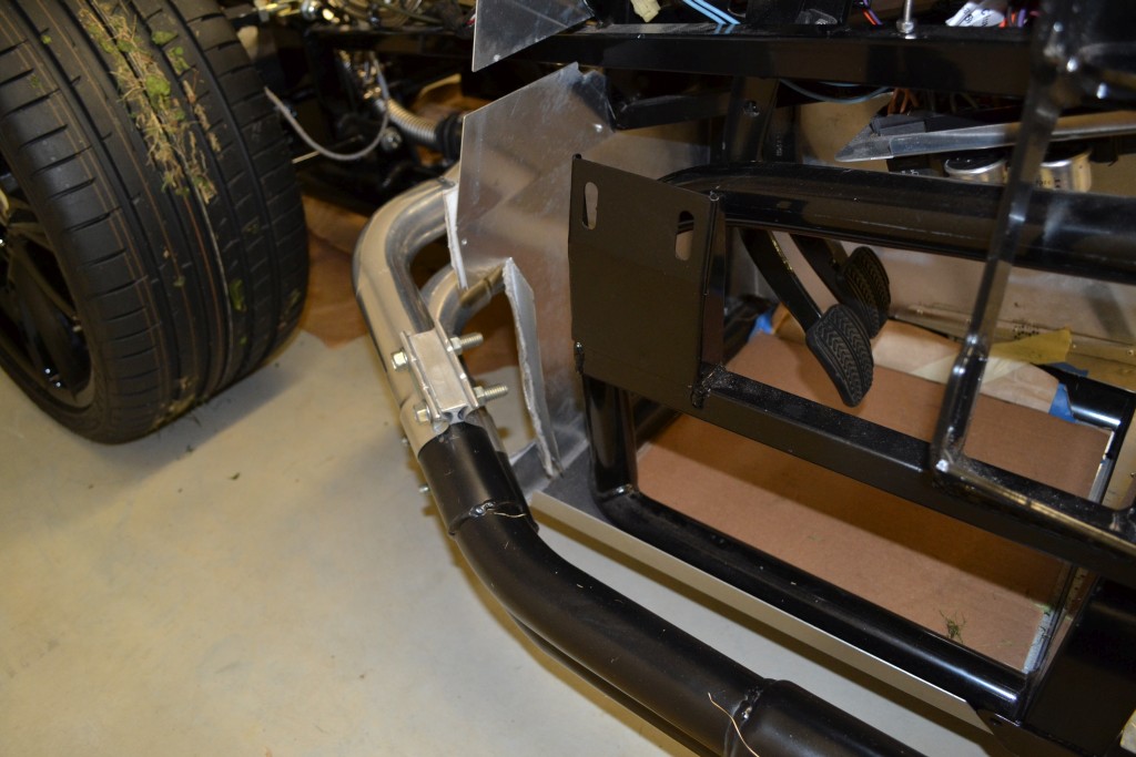
Back to the drivers side, the header was slightly touching the corner of the driver's foot box. To gain more clearance, I cut the footbox and bent it in. I still need to make the outside piece fit, and will get to this soon.
Here you can see the cut in the footbox that I needed to make (as well as the grass still on the tires from my first go kart) to provide clearance for the header. Since my foot could never get in that corner, it shouldn't really impact the room in the footbox.:
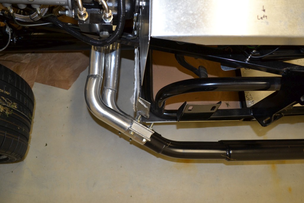
Here are a couple of pics of the passenger side of the car showing the black pipes and how the car sits now:
I didn't install the hangers yet and will wait to do this after the body is on.
-Matt
-
Hazard and Turn Signals
Back to the electric and the hazard switch and turn signals. For the hazard switch, I used the ON-ON double pole switch from the kit. For the turn signal, I was using the Russ Thompson turn signal. It took a bunch of research to figure out how I wanted to connect it up. Eventually I settled upon the following schematic:
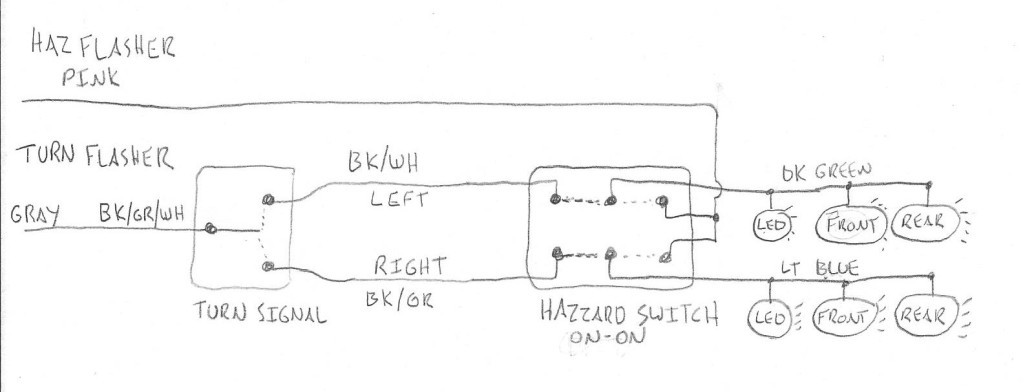
Normally, the hazard switch will be in the down position (connecting left to middle in the above picture), which connects the turn signal path. The middle connection of the hazard switch goes to the dash LED and front/rear lights for each side. Then the turn signal will function.
With the hazard switch in the up position (connecting right to middle in the above picture), the turn signal will be bypassed and since the hazard flasher connects to both the left and the right side of the switch, both sides will flash.
-Matt
-
-
Front and Backup Cameras
I wanted to have a backup camera on the car since I figured it would probably be difficult to see out the back. Then I decided, why not a front one as well? I spent a bunch of time trying to research different ones as well as how to display the pictures.
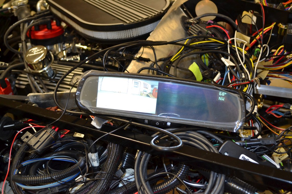
I decided that I wanted to use the rear view mirror to display the cameras. I ended up getting the CrimeStopper SecurView SV-9156.CT. This has a 4.3" LCD Screen, Compass and Thermometer and has 2 inputs.
For the cameras I got 2 PyleView PLCM38FRV cameras which can be used as a forward or a reverse camera (ie. flip image). There are 3 wires on the camera that can be tied together to reverse the image and show distance lines. For now I have the distance lines off and the rear camera reversed.
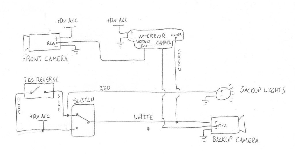
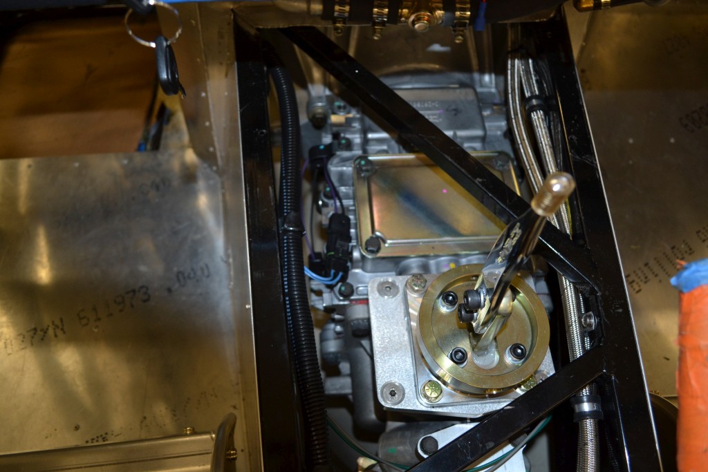
Now for the fun part, hooking them up. Again back to the pencil and paper to map out the connections. I wanted the backup camera to turn on when in reverse, so I needed to use the reverse switch on the TKO500. To connect to that I bought the Ron Francis Wiring Transmission Backup Light Connector Pigtails PG-055. I also added in a manual override switch to turn on the backup camera when I wanted, while not in reverse. So I can see who's tailgating me. :) I didn't want to turn on the backup lights when using this manual override switch, so I can use it while driving and not have the backup lights turn on. This required me to connect it via the schematic below.
The front camera will be powered all the time and the display can be turned on/off by a button on the mirror. So when the ACC is on, the front will display. If in reverse or I override it, the back will display.
There's a green wire on the mirror that when at +12V will display the backup camera, so this had to be wired in.
For the backup lights, I bought 2 Marker Lights - L488-Clear from Finish Line Accessories which match the Factory Five tail lights.
Here's the schematic:
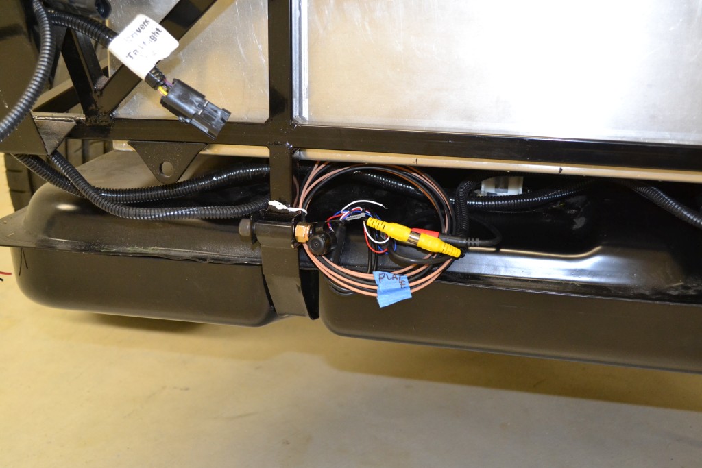
Backup camera (not the final mount):
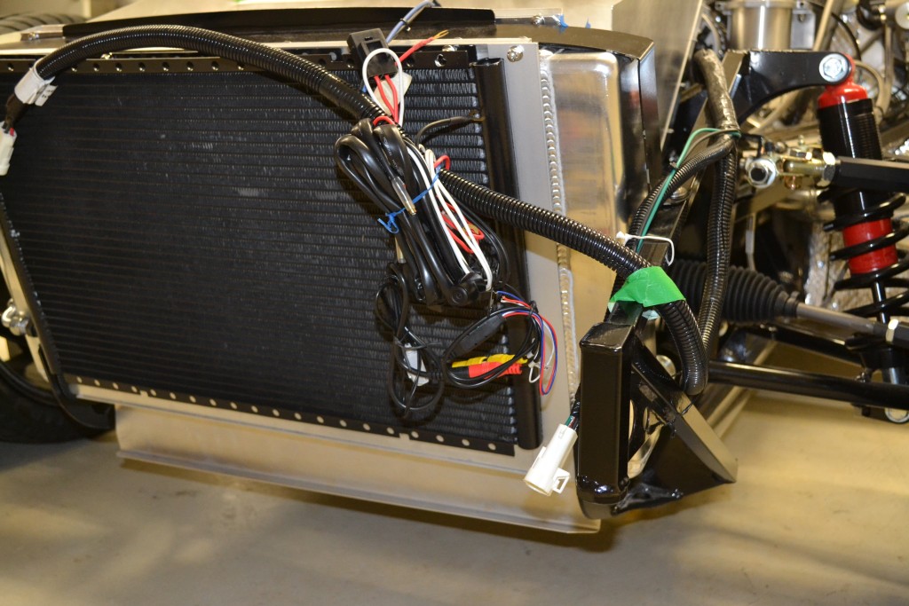
Front camera (not the final mount):
TKO pigtail. Hard to see.
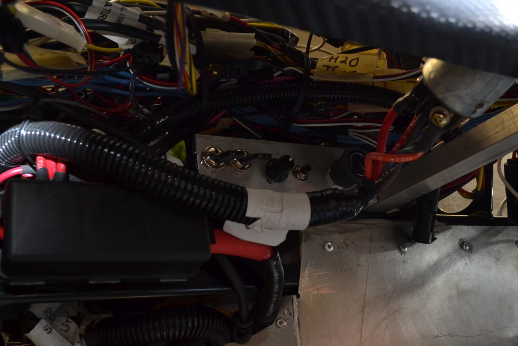
Override switch under the dash. The switch on the left is the backup camera override. Next to that is the radiator fan override switch, the dash dimmer, clock set button and AC temp knob.
Here's a picture of the mirror showing the front camera. Also has the direction and the temperature.
Lastly, I had to make a video to show it in action. Enjoy. :)
-Matt
-
-
Senior Member

-

Steve >> aka: GoDadGo

So Totally Cool!
Congratulations On This HUGE Milestone!
-
-
-
-
-
-
-
-
-
-
-
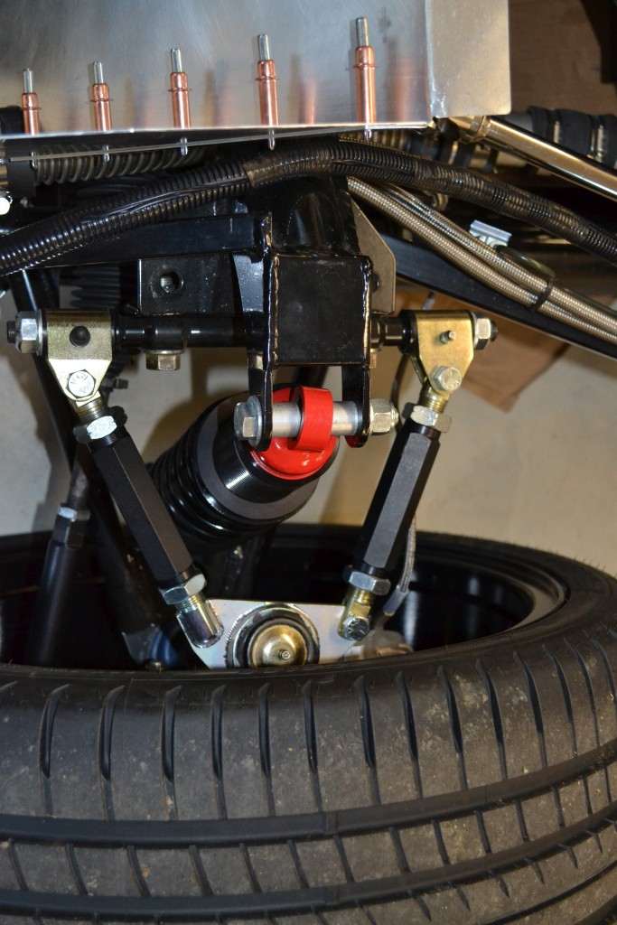
Alignment
A few weeks back, I made an attempt to roughly align my car. I set the ride height. I drew some lines on the floor parallel to the frame, then some more near the wheels. I spent many hours over a few nights to get it close. With the IRS, it's a pain to make the adjustments.
I decided that before I go further with the trunk aluminum panels and the body, that I'd take it in and get it aligned. I've been trying to read up of various alignment threads and settings. Trying to figure out the toe in, caster and camber settings to use. Since I was running power steering, I settled on 7degrees caster. For both the front and rear, I would use 1/16th in toe and -0.5degrees camber. I saw some posts regarding the number of thread engagement for the front, so before I brought it in, I took a few pictures to see.
The threaded sleeve is 4"
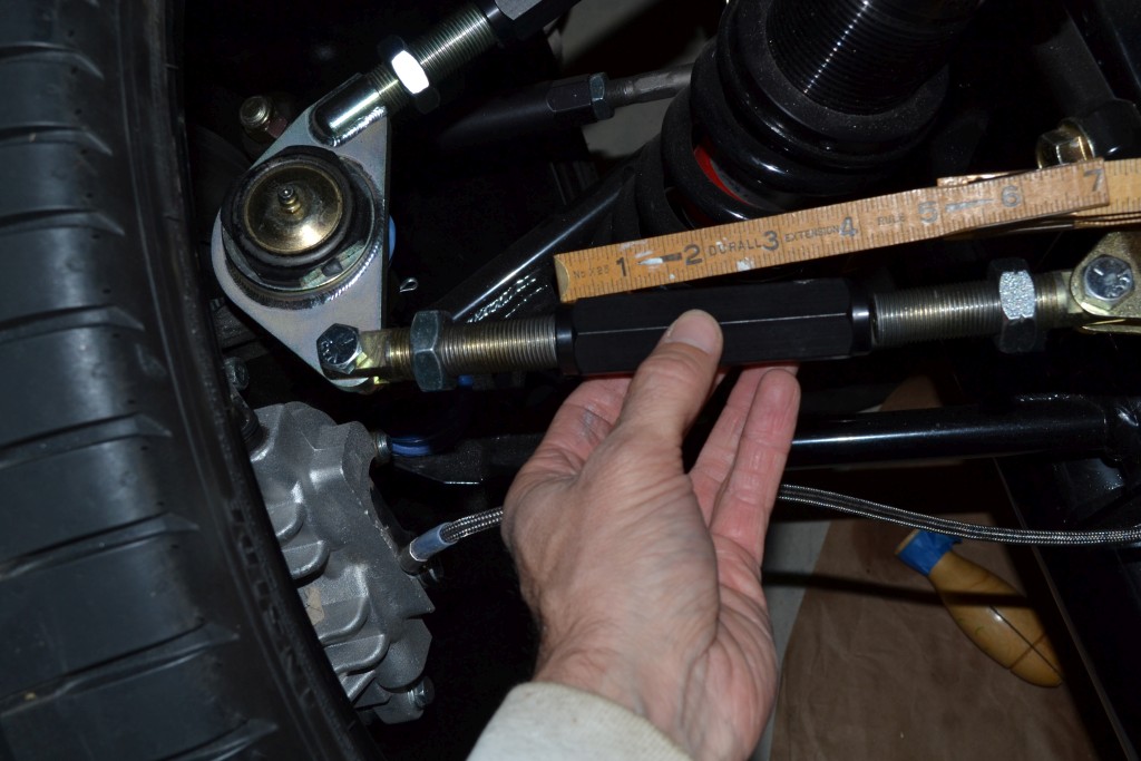
The rods have 2.5" of thread
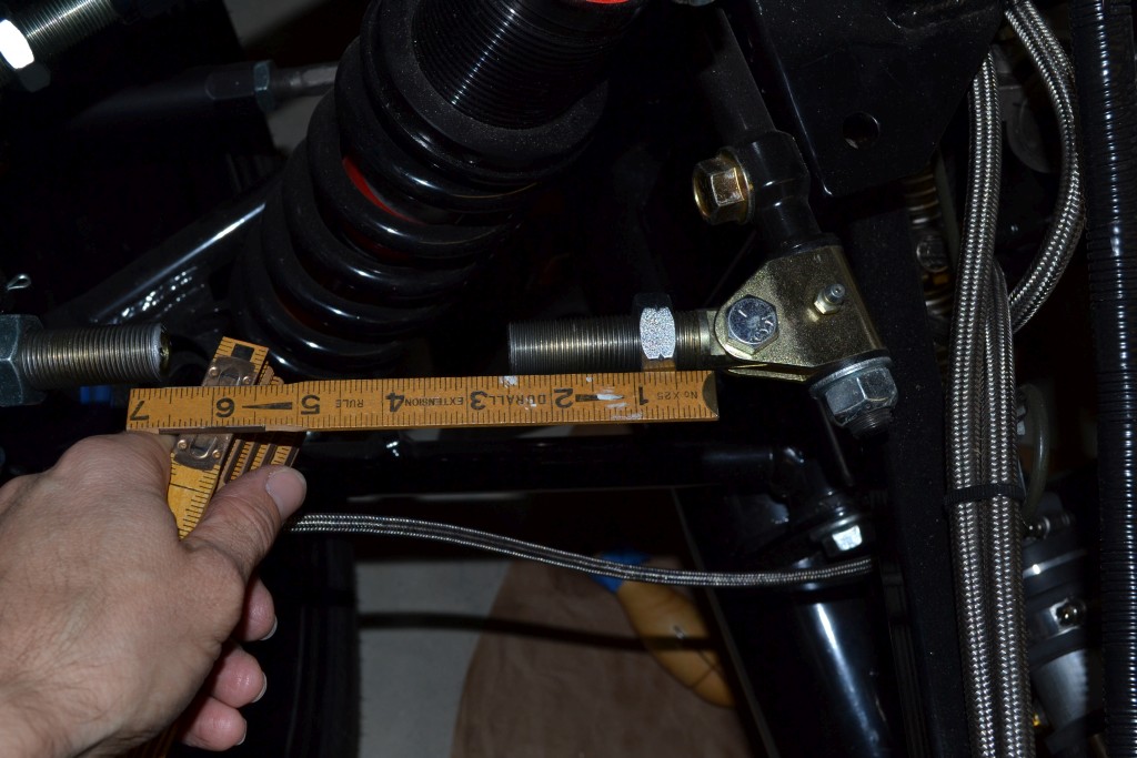
With those lengths, it doesn't appear as if I'll have an issue with too little thread engagement.
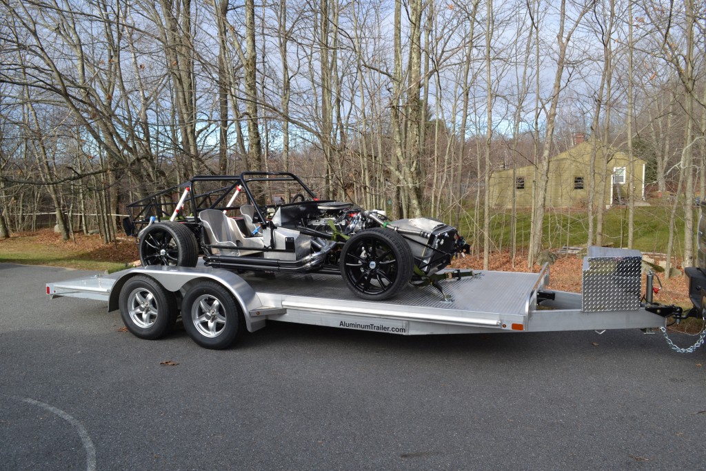
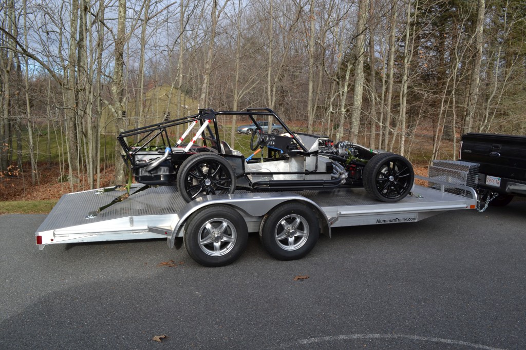
My Dad and I loaded it up on the trailer and were ready to go.
We got to the shop and I drove off the trailer and into the bay and up on the lift. The guy put the sensors on all the wheels and he had at it. We started with the back and I had done a pretty good job. He didn't touch the left rear wheel and just needed to tweak the right rear. At first he did one complete turn of the front adjustment. It was too much, so he went back 1/2 turn. 1/2 turn results in 3/32" toe in change. The back was set.
Then on to the front. When trying to get the caster at 7degrees, we quickly found out that with 4" sleeves, the most we could get on the passenger side was ~4degrees. To get more, I'd have to get a smaller sleeve on the rear or cut the ones I have. I figured 4 was good enough for me for now. If I want to change it later I could. He then matched the driver's side and adjusted the toe. Seemed like it was good enough for now. I'll probably take it back in after a year on the road. Drove it out and back on the trailer and back home.
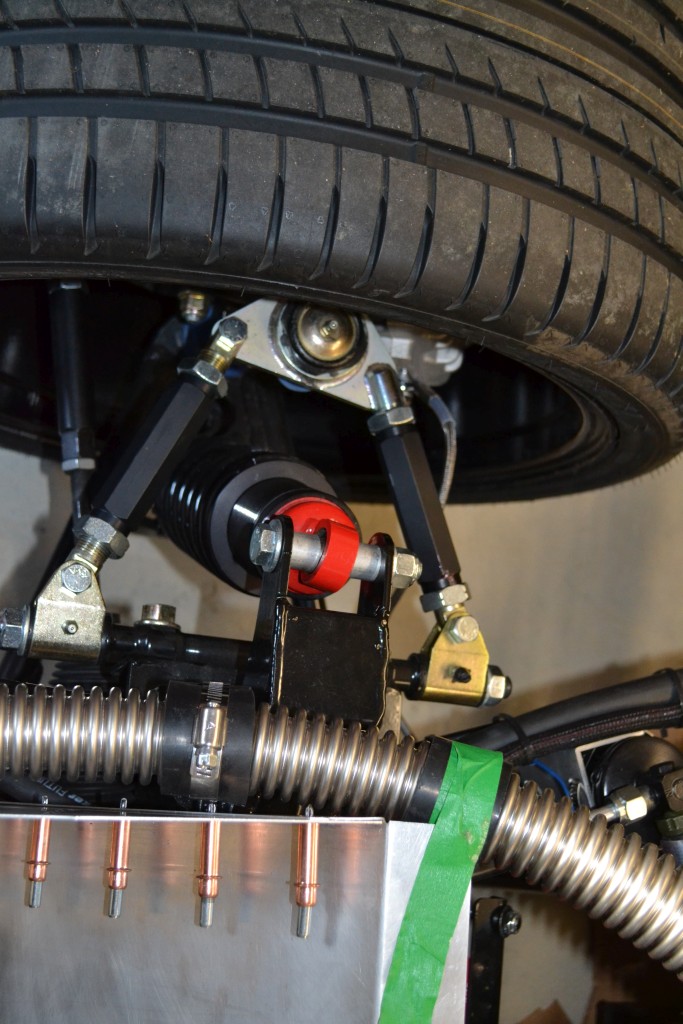
Results. Here's how we ended up.
Passenger side final. You can see rear part is as small as it can be.
Driver side final
-Matt
-
-
-
-
-
Looks great. Re-welding the headers seems to be a rite of passage for Gen 1 and 2 coupe builders, from what I can tell. Carry on!
-
-
-
-
-
Matt-
She's coming along, or should I say she has come along...
Nice updates on your past progress.
Regards,
Steve
-
Thanks Steve,
Yeah, like almost everything with the building of the car, it's taking me longer than expected to post all of this. I'm about 1/3 done updating these posts.
It is fun going back and re-reading all of this and remembering what it used to look like.
Thanks.
-Matt
-
-
Wiper Motor cont.
With the motor mounted.
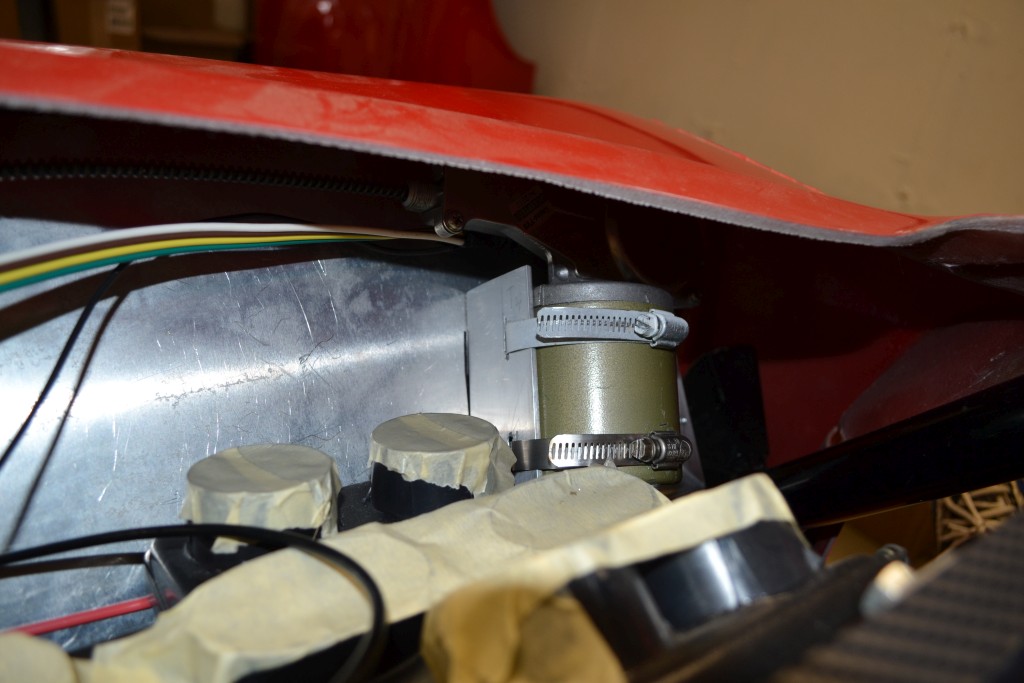
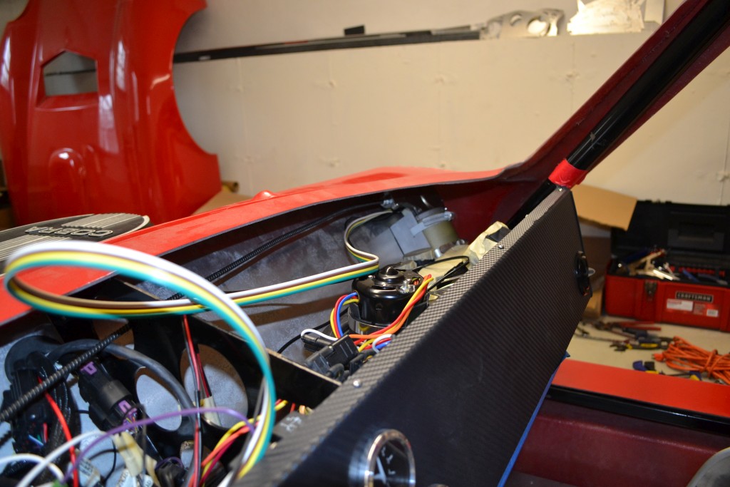
With the motor in position and mounted, it was time to mount the wiper and wiper boxes.
-Matt
-
-
-
-
Hood
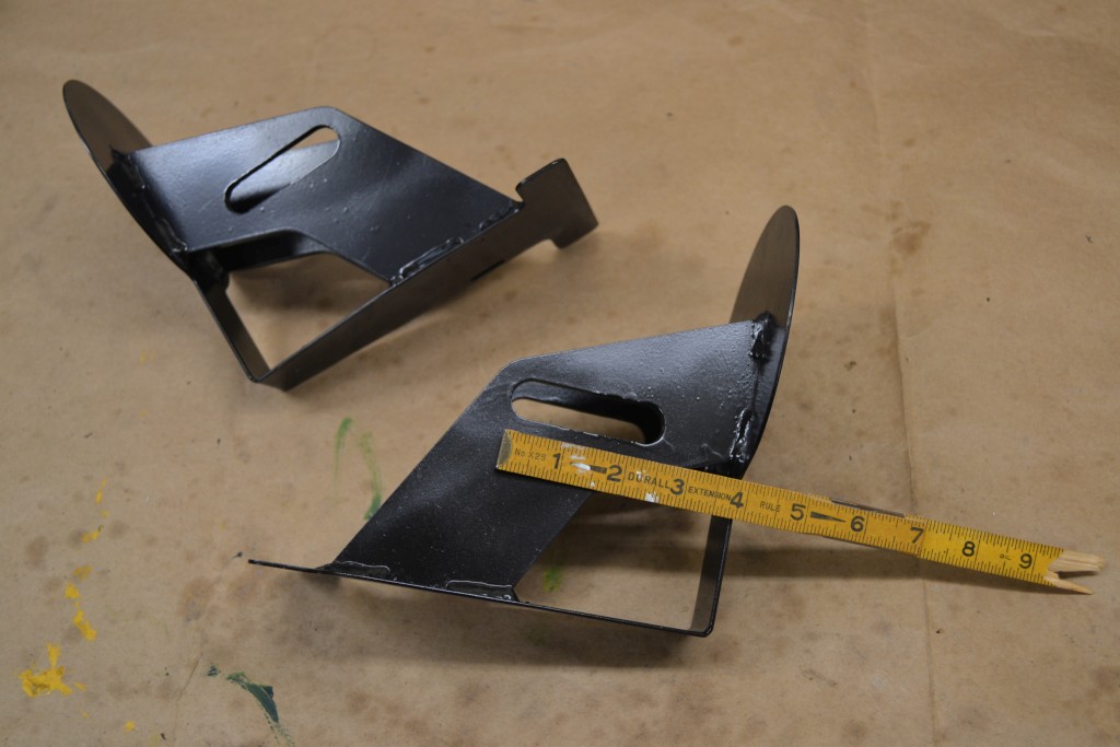
After reading up on other people's posts about mounting the hood, I decided I was ready to give it a shot for myself. After a quick test fit holding the front up on jacks and trying to gauge where the hinge brackets would go, it did look like I'd have to elongate the holes to get the hood to line up with the body pontoons. Rather than take a little off at a time, I just decided to do it in one big chunk. So I drilled a hole 3/4" from the edge of the current slot. Then took a dremel to cut between the slot and the new hole.
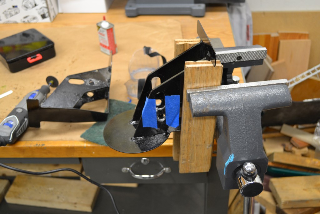
After dremeling and filing, then a quick paint touch up, the slot was now 2 1/2" long, which should be more than enough. It looked like there was still enough meat left on the bracket. This picture reminds me that I need to glue my ruler back together after accidentally stepping on it the other day.....
Put the washers and spacers in and put the rod ends fully threaded up.
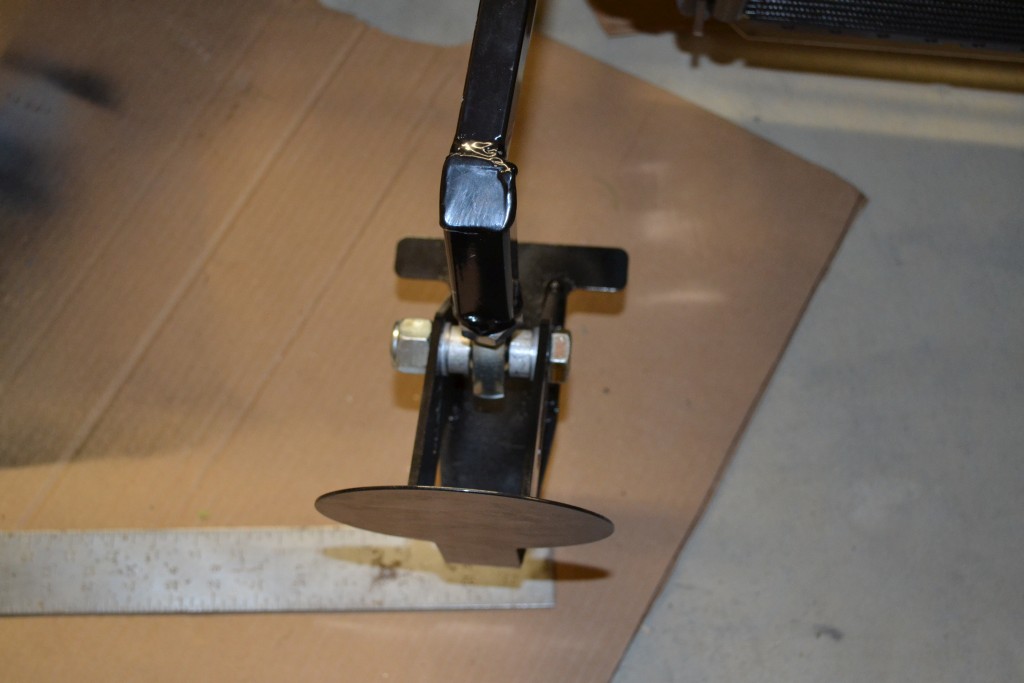
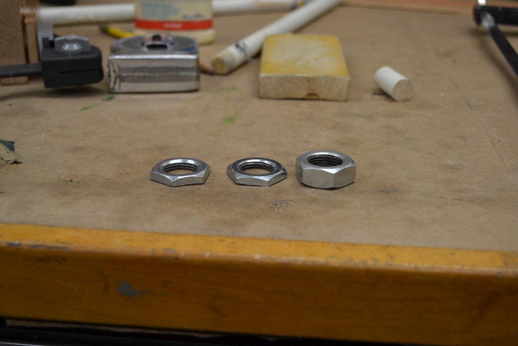
With the jam nuts on and fully threaded, I put the hood back on the car. After a few days tweaking/measuring making sure it was fairly well centered, overhang on the wheels even, lining up with the pontoons, checking the gap to the pontoons, the hood looked pretty close the correct height with the jam nut on and only a couple threads showing. I still wanted to give myself a little more room for adjustment up and down if necessary, since the hood still needed to be trimmed, so I'm not exactly sure how it will sit (ie. gap between hood and pontoon) once this was done. So I cut the jam nut in two which gave me a little more room. Time will tell if I needed to do this or not. Then gave them a quick shot of paint as well.
I put the hood back on the jacks and positioned where I wanted one last time. Next was to drill the holes through the fog mounts and mount the fog light bracket and also an additional bolt on the top of it with a big washer.
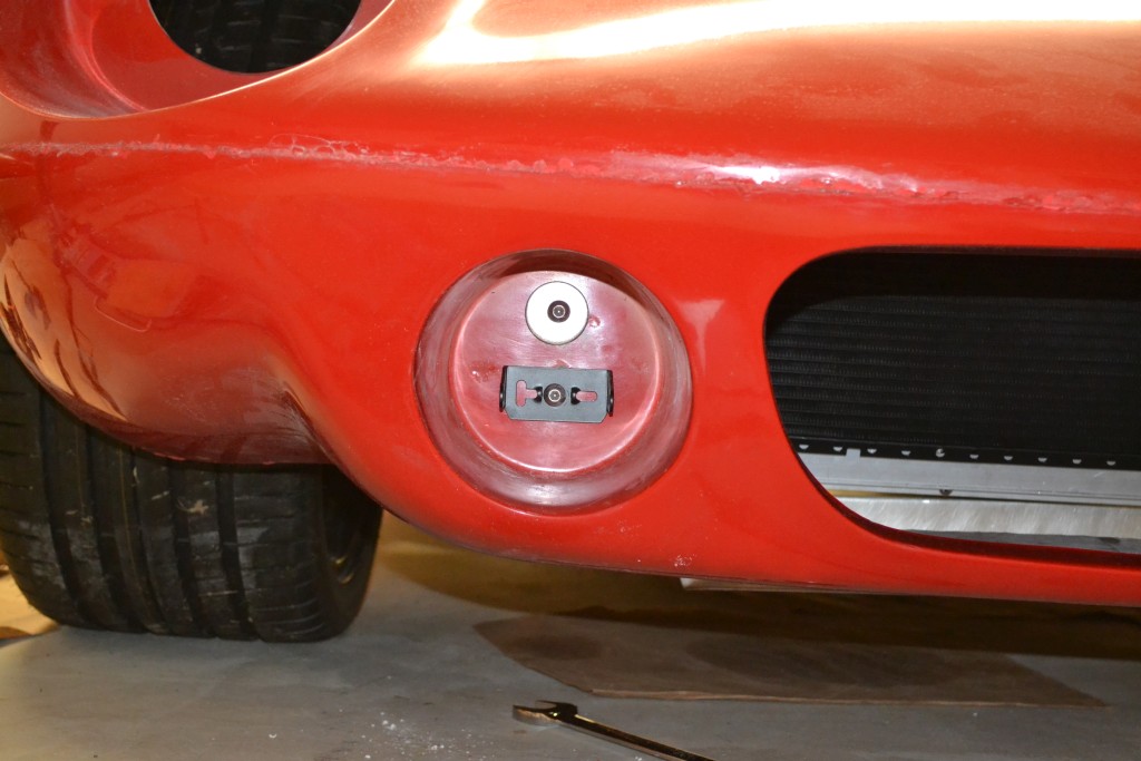
Got both on

-
-
-
-
-
 Posting Permissions
- You may not post new threads
- You may not post replies
- You may not post attachments
- You may not edit your posts
-
Forum Rules

Visit our community sponsor


 Reply With Quote