FormaCars

Visit our community sponsor

Thanks Thanks:  0
Likes Likes:  0
Results 1 to 12 of 12

Thread: Wiring Questions

  1. #1
    Senior Member EZ$'s Avatar
    Join Date
    Feb 2014
    Location
    San Ramon, CA
    Posts
    951
    Post Thanks / Like

    Wiring Questions

    As I plod along with the wiring, I ran across a couple of items that I'm not sure how to proceed.
    First, I thought that I had read, somewhere on the forum, that the radio circuit could be used as power for a power port. I had purchased a pair of power ports, one a cigarette lighter style, and the other a USB. Would the radio circuit, with possibly a larger fuse, be enough to handle the power for both ports?
    Second, I'm installing an additional fuse panel, a Blue Seas 12 position, with them divided 6 and 6, powered all the time, and in run only. I figured that the "in run only" would need to be routed through the ignition switch, but I thought, again from something that I read here, that it's not a great idea to connect something like this, (fuse panel), directly to the ignition switch. If that is the case, how can I power this side of the fuse panel, and not chance frying something else, like the ignition switch.

    I guess it's starting to make sense why this is taking me so long!
    Thanks.
    Rick

  2. #2
    Supreme Cobra Commander TimC's Avatar
    Join Date
    Feb 2011
    Location
    Flowery Branch, Ga.
    Posts
    317
    Post Thanks / Like
    The radio circuit should plenty of power for the outlets you're planning on. For the run circuit use a standard Bosch type relay and the ignition switch to trigger it.
    Tim.

    Knowledge is good-Faber.

    I'm so broke I can hardly pay attention-Me.

  3. #3
    Senior Member EZ$'s Avatar
    Join Date
    Feb 2014
    Location
    San Ramon, CA
    Posts
    951
    Post Thanks / Like
    Tim, Thanks for confirming the ability to use the radio circuit for the power ports. Is there any way you could explain how the relay would be wired into the ignition to power the HIR side of the fuse panel? Any way of determining how much power would be available at the fuse panel?
    Thanks for the help.
    Rick

  4. #4
    Moderator
    Join Date
    Apr 2017
    Location
    Sacramento CA
    Posts
    452
    Post Thanks / Like
    A fuse is the weak point in a circuit, dont just up the amprage of the fuse ( put in a bigger fuse), if you are just charging usb items leave the fuse alone. If it blows then figure why, how much amperage you are pulling, etc.

    The relay for the 12v can be fused between the battery and the relay, that is how much power you can pull. If not it is untill things start smoking. Lookup relay wiring diagram and you will find lots of pics. Look up your relay to find what terminals go to what.

    Technically speaking, you can pull all the power you want untill a fuse blows or wires melt down.
    Last edited by Just puttering; 11-13-2018 at 11:45 PM. Reason: Slight adjustment
    Mk3.1 347 AFR 205cc Heads A9L EFI siemens deca 60lb injectors MSD 6AL ignition Vortech V-3 3 Link PS/PB

    -- If you can’t fix it with a hammer, you have an electrical problem ! —

  5. #5
    Senior Member edwardb's Avatar
    Join Date
    Feb 2011
    Location
    Lake Orion, Michigan
    Posts
    10,781
    Post Thanks / Like
    Couple of suggestions.

    (1) Don't change the amperage value of fuses in the Ron Francis panel. The wire sizes and fuses used in the harness for each circuit are sized for the expected current draw. If your USB port needs more current than the radio circuit is rated for, you'll need to find another circuit. Yes, the fuse is the weak link and if that blows you'll know you need more power. Personally, I'd approach it a little more systematically than that, but would certainly be an indication. Only upping the amperage value of the fuse could lead to the smoke and melting wires mentioned, with potentially disastrous results. Don't do it.

    (2) Would be helpful to know the part number of the Blue Seas panel you're using. Based on looking, maybe #5032? I've used auxiliary panels before. Some, e.g. from Painless, have a built-in relay to easily wire always on and ignition on circuits. Doesn't look like this one or other Blue Seas offerings have a built-in relay. They're expecting you to provide the switch power. As already mentioned, there are lots of diagrams out there for wiring a relay. In simple terms, six of your circuits will be directly connected to the battery. The other six will also be directly connected to the battery, but switched on and off through the relay using a +12V signal from any ignition powered circuit or the ignition switch itself. The relays carries the current load (so it must be properly rated) rather than the ignition switch. Which it sounds like you've heard not to do, and that's correct.
    Last edited by edwardb; 11-14-2018 at 07:35 AM.
    Build 1: Mk3 Roadster #5125. Sold 11/08/2014. Build 2: Mk4 Roadster #7750. Sold 04/10/2017. Build Thread
    Build 3: Mk4 Roadster 20th Anniversary #8674. Sold 09/07/2020. Build Thread and Video. Build 4: Gen 3 Type 65 Coupe #59. Gen 3 Coyote. Legal 03/04/2020. Build Thread and Video
    Build 5: 35 Hot Rod Truck #138. LS3 and 4L65E auto. Rcvd 01/05/2021. Legal 04/20/2023. Build Thread. Sold 11/9/2023.

  6. #6
    Senior Member CraigS's Avatar
    Join Date
    Feb 2011
    Location
    Blacksburg, Va
    Posts
    4,921
    Post Thanks / Like
    What amp fuse powers the radio circuit? That will tell you what you can run from that circuit. I'd be fairly confident that it will power the usb circuit but the lighter style circuit could end up w/ something drawing too much current depending what you plug into it. As already mentioned it's not a good idea to increase the fuse amperage at all. You are already planning the extra circuit panel so I'd power the lighter circuit from one of those. BTW, since those extra circuits will be wired completely by you, research 12V amperage and required wire sizes. Pay particular attention to the main power lead. It needs to be able to handle the load of all 6 fuses at once. In other words, if you decide that you will have six 10A fuses, the power lead needs to be able to handle 60 amps. So start by figuring out what you expect to power, and how much current each item will need. As you research, you will get a feel for common items and how many amps they draw. So, if you decide you will initially power 4 items, two 15A and two 10A, then decide on how much extra current you want to have available for the other two empty fuses. The four add up to 50amps, so, if you want to be able to handle two more 15A circuits later on, you need to get 80A to that panel. Once you get all that figured out look into locations. You want to place the extra panel where the power from the battery will have it's shortest run and the wire can be really well insulated because that wire is not fused.
    FFR MkII, 408W, Tremec TKO 500, 2015 IRS, DA QA1s, Forte front bar, APE hardtop.

  7. #7
    Senior Member EZ$'s Avatar
    Join Date
    Feb 2014
    Location
    San Ramon, CA
    Posts
    951
    Post Thanks / Like
    Just Puttering, I definitely want to avoid smoke! I'll look up those relay wiring diagrams.

    Paul, I think the USB port can be handled by the radio feed. I can run another circuit from the new panel for the lighter style circuit, as Craig mentioned, and I'll leave the fuse in the radio circuit alone. It is the #5032. I'm going to research the relay wiring, and try to figure out the HIR side of the panel. As a note, should I have any protection between the PDB and the fuse panel for the HATT side?

    Craig, I'll check to make sure that the wire sizes are correct on all the wiring that I end up doing. I obviously have a lot of research ahead of me to wrap my head around all of this.

    Thanks for all the input guys. I'll figure this out....eventually!

    Rick

  8. #8
    Senior Member edwardb's Avatar
    Join Date
    Feb 2011
    Location
    Lake Orion, Michigan
    Posts
    10,781
    Post Thanks / Like
    Quote Originally Posted by EZ$ View Post
    As a note, should I have any protection between the PDB and the fuse panel for the HATT side?
    Shouldn't be necessary since anything attached to the fuse panel goes through its fuses.
    Last edited by edwardb; 11-15-2018 at 08:07 AM.
    Build 1: Mk3 Roadster #5125. Sold 11/08/2014. Build 2: Mk4 Roadster #7750. Sold 04/10/2017. Build Thread
    Build 3: Mk4 Roadster 20th Anniversary #8674. Sold 09/07/2020. Build Thread and Video. Build 4: Gen 3 Type 65 Coupe #59. Gen 3 Coyote. Legal 03/04/2020. Build Thread and Video
    Build 5: 35 Hot Rod Truck #138. LS3 and 4L65E auto. Rcvd 01/05/2021. Legal 04/20/2023. Build Thread. Sold 11/9/2023.

  9. #9
    Senior Member EZ$'s Avatar
    Join Date
    Feb 2014
    Location
    San Ramon, CA
    Posts
    951
    Post Thanks / Like
    Thanks Paul. I figured the way things have been going if I decided the answer was NO, the answer would be YES, and vice versa!

    Rick

  10. #10
    Moderator
    Join Date
    Apr 2017
    Location
    Sacramento CA
    Posts
    452
    Post Thanks / Like
    If you havent found it yet, look up auto wiring capacity, look in the pictures area and you will get a good visual on wire size to length and current for the wire.

    Most of the relays people reference here are fairly standard. A relay diagram that shows the internal parts of a relay can be used for another relay if you know the internal setup of your relay. You need to be sure to match yours to the diagram or visa versa. Versa visa ... ( the other way around).

    Your relay will have power in and a ground and power out and the signal wire that is your 12v in run wire.

    Think of a light switch but you are the 12v in run signal when turning it on and off. The 12v in run is just throwing a switch.

    If possible, and you want clarification on something, try to make a diagram and post it. It is difficult to check if your circuit makes sense reading text. Look up auto wiring symbols for help when making your diagram.
    Mk3.1 347 AFR 205cc Heads A9L EFI siemens deca 60lb injectors MSD 6AL ignition Vortech V-3 3 Link PS/PB

    -- If you can’t fix it with a hammer, you have an electrical problem ! —

  11. #11
    Senior Member CraigS's Avatar
    Join Date
    Feb 2011
    Location
    Blacksburg, Va
    Posts
    4,921
    Post Thanks / Like
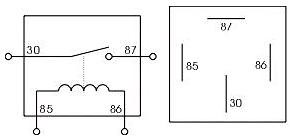
    This is a standard relay diagram
    4-pin-automotive-relay by craig stuard, on Flickr
    Convention is that your main power comes in on pin 30 and goes out on pin pin 87. Pins 85 and 86 are for the operating coil. Depending on what you are doing it is often easiest to get the power for the coil by a short lead from pin 30. You can put two wires on 30 using something like this
    https://www.delcity.net/store/Non!In...02001.h_795480
    or like this
    https://www.delcity.net/store/Nylon!...05401.h_798356
    I prefer to activate the relay by having the power to the coil and then the ground side of the coil is connected to your dash switch. Another neat thing about a relay is that it can be controlled by two other items. Say you want to run driving lights but you want them to come on only w/ the low beams. Power the coil from the low beam hot lead and ground the coil w/ your dash switch.
    FFR MkII, 408W, Tremec TKO 500, 2015 IRS, DA QA1s, Forte front bar, APE hardtop.

  12. #12
    Senior Member EZ$'s Avatar
    Join Date
    Feb 2014
    Location
    San Ramon, CA
    Posts
    951
    Post Thanks / Like
    Just Puttering, I found that chart, and printed it out so that I can post it in my shop for reference. I'm trying to make sure that I get the correct size relays in the right locations. Once I start to feel like I'm getting a handle on this, I'll try to put together a diagram, and as I've mentioned before, you guys can let me know how long it will take till I burn this thing to the ground! (No pun intended).
    Craig, Interesting connectors. I never realized they made anything along these lines. I will keep in mind the other options on relays.
    Thanks guys,
    Rick

Posting Permissions

  • You may not post new threads
  • You may not post replies
  • You may not post attachments
  • You may not edit your posts
  •  

Stewart Transport

Visit our community sponsor