-
12-10-2018, 12:46 PM
#121


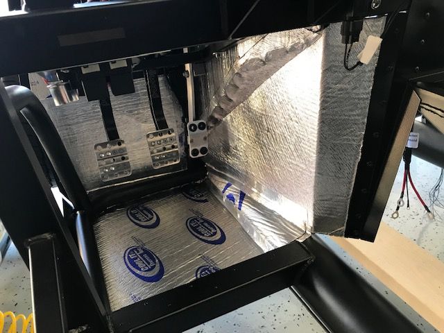
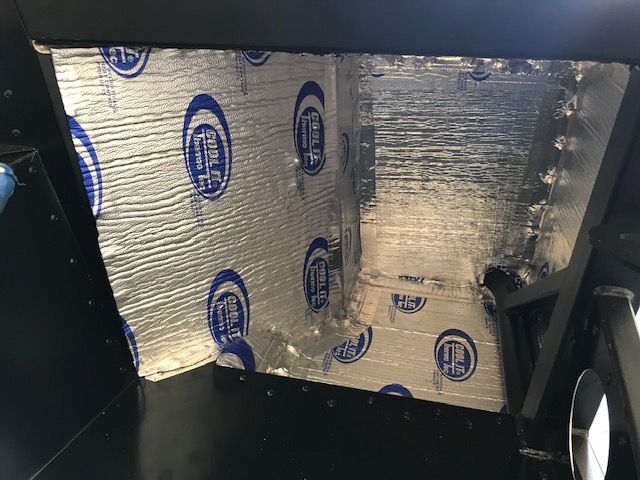
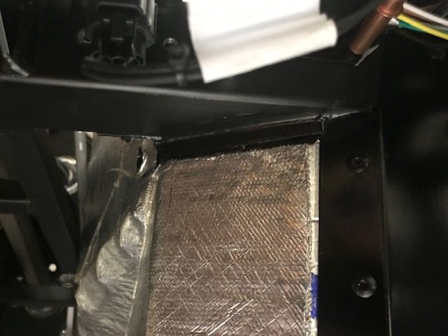
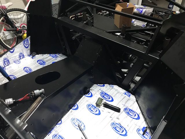
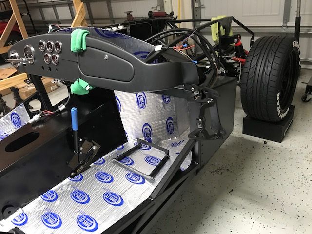
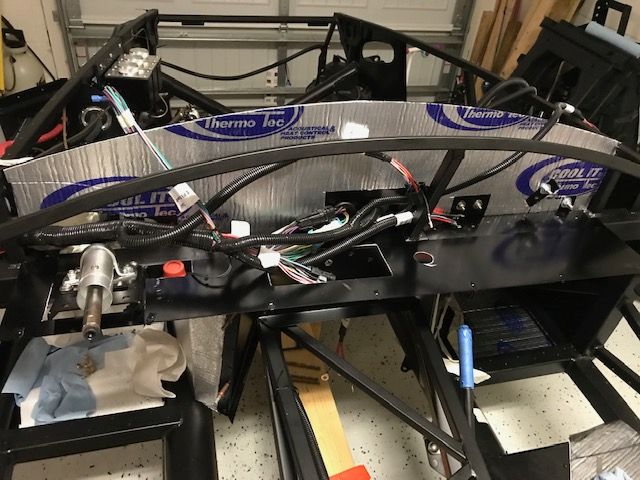
Next up was the dash and firewall. I installed some Thermotec on the firewall and temporarily put my under dash filler panel in place from replicaparts.com.
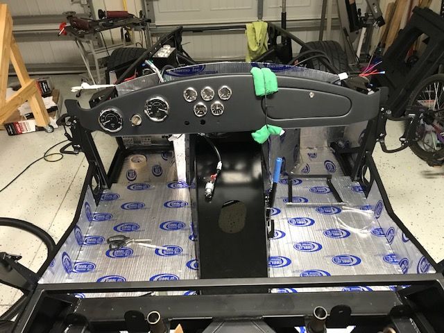
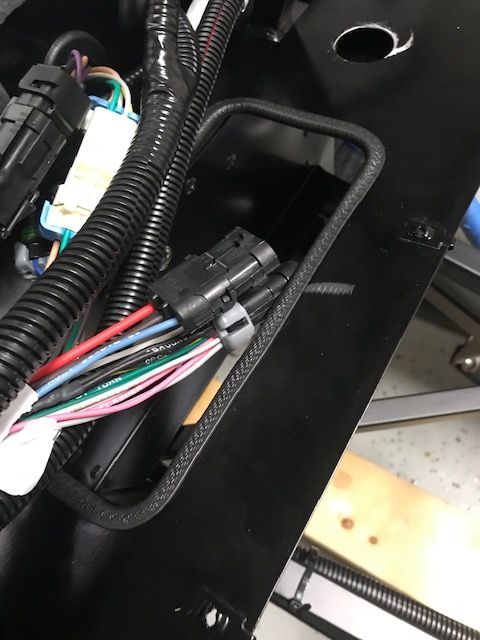
The underdash panel is very nice gauge aluminum and affixes to the 2" beam. I cut a 4"x6" square in the middle for easy access of wiring later on down the road and will be putting some trim around it for detail. I also had to widen the section around the pillow block/steering boss as I don't think the design has been changed as of yet for the new FFR design. Took 5 minutes, so not a big deal. I also cut a hole for a USB charging port, inertia switch as well as the dimmer switch for the lights.
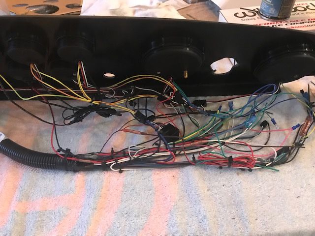
On to my dashboard. I have everything wired up at this point, using the Perma Seal butt connectors. Only issue I ran into while wiring was one of the water temp gauge connectors was wired backwards on the RF harness. Called Ron Francis and they sent out new connectors, pins and a removal tool. Excellent customer service!!
Still cleaning up the wiring a little but will say that the dash is a pretty impressive piece. At first glance, you think its just molded plastic to look like material, but its actually a leather like material molded to the plastic top. I think it will hold up very well to the elements as you don't have to worry about glues or lifting...at least I don't think...
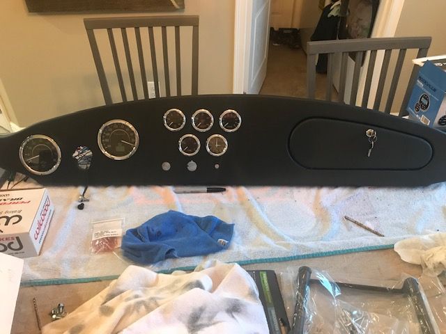
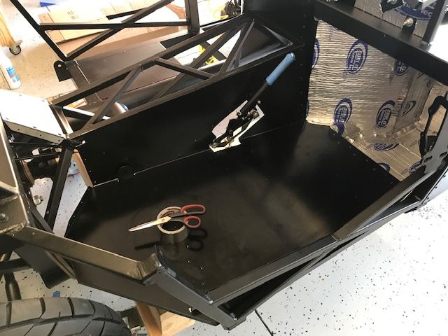
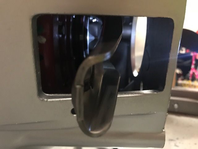
Per the picture, the glovebox was also completed. Couple of things here. Badasp recommended the JB Weld Plastic Bonder #50139 for the metal hinges to the plastic. Carl was right and this stuff bonded perfectly. I'd guess the door would tear up before this comes unbonded, but time will tell. I'll get some kind of black covering to blend it in with the door.
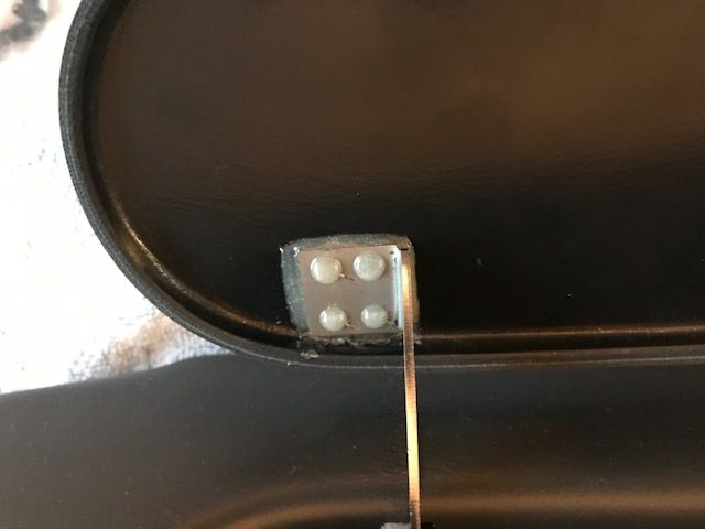
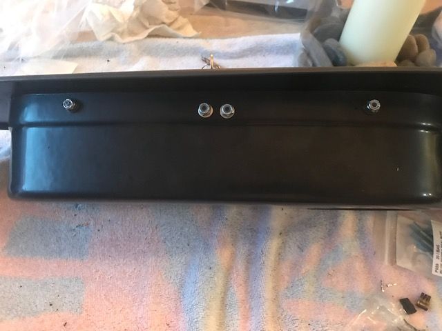
After I put the glovebox together, the only screws holding the box itself at the top were the locking plate screws so I could have either used a glue of some kind of affix the box a little better to the dash or some additional screws. I chose the screws so now it's rock solid.
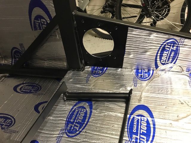
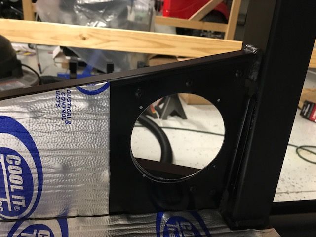
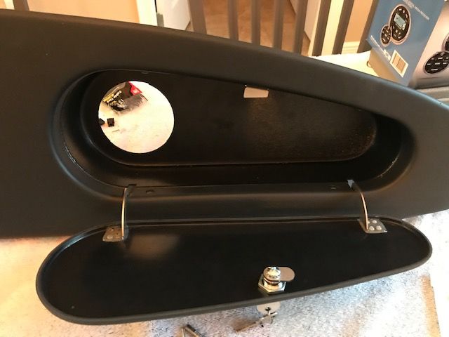
I am also planning on a wifi radio, so cut a 3" hole at the back of the glovebox that fits the Rockville circular radio perfectly with less than 3" of mounting depth. By the way, a variety of hole saw sizes in one kit can be had at Harbor Freight for less than $10 and worked great.

Last edited by cv2065; 12-10-2018 at 12:50 PM.
-
12-10-2018, 12:55 PM
#122
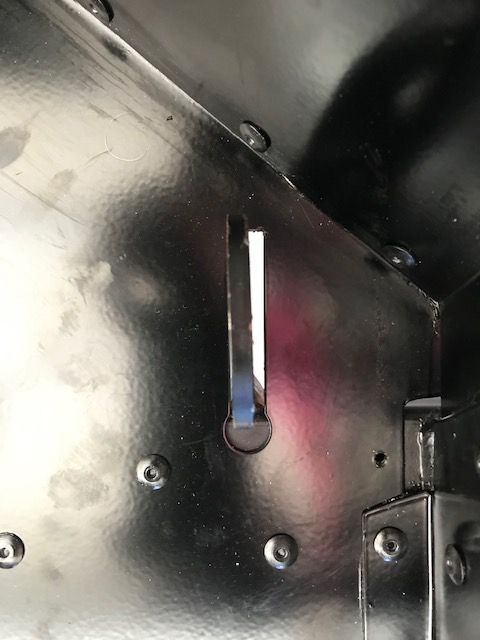
Last thing for the dash was to enlarge the steering column hole to accommodate the RT turn signal mod. As other's have said, the plastic cut very easily and I scored it from the back with an Exacto knife. I fitted it but might need some additional minor trimming once temp installed, which will be soon.

-
12-10-2018, 01:35 PM
#123
Senior Member


Originally Posted by
cv2065

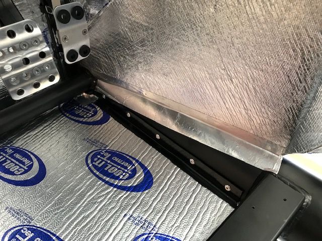
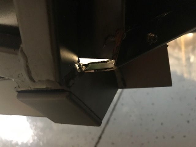
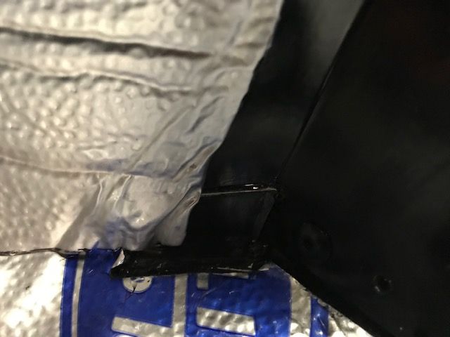
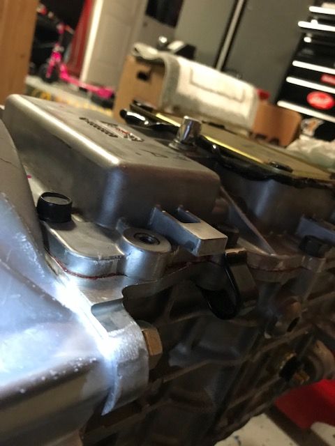
After reading another build thread I saw Jeff Kleiner's post about the brackets and swivel bushing for the steering shaft needing to go on the OUTSIDE of the driver's box. Checked mine and this wasn't the case. Even though some have put it inside like I had it, I wanted to get it perfect, so disassembled it all and without the additional slack at the PS fitting, it literally fit like a glove. Now I know why the steering column comes in two pieces. You have to disassemble quite a few things to get it to fit back up through the pedal box if it has already been put together. But it's completed and we are good to go.
Just to confirm, you have both sides of the pressed steel flanges flanges of the steering column bearing assembly on the outside of the footbox? It's not 100% clear from your picture. Just wanted to confirm you're not describing having one half inside and one half outside. That wouldn't capture the bearing properly.
BTW, absolutely nothing wrong with having to mount the bearing assembly on the inside of the footbox, other than it's a little harder to assemble. But once there, accomplishes exactly the same thing. The problem some have had (including me) is with the bearing assembly on the outside, with some steering racks the universal joint on the steering column bottoms out in the bearing before the other end can be engaged into the steering rack. Some have resorted to loosening and moving the entire rack in order to get the steering column plugged in. Way too much work. In that case, put the bearing assembly on the inside. The other reason to put it on the inside, which doesn't come up too often any more, is that some footbox mounted PS boosters would interfere with the bearing on the outside. Again the solution was to go inside. If yours works OK on the outside, which is also how the FF instructions show, then great.
Build 1: Mk3 Roadster #5125. Sold 11/08/2014.
Build 2: Mk4 Roadster #7750. Sold 04/10/2017.
Build Thread
Build 3: Mk4 Roadster 20th Anniversary #8674. Sold 09/07/2020.
Build Thread and
Video.
Build 4: Gen 3 Type 65 Coupe #59. Gen 3 Coyote. Legal 03/04/2020.
Build Thread and
Video
Build 5: 35 Hot Rod Truck #138. LS3 and 4L65E auto. Rcvd 01/05/2021. Legal 04/20/2023.
Build Thread. Sold 11/9/2023.
-
12-10-2018, 01:53 PM
#124
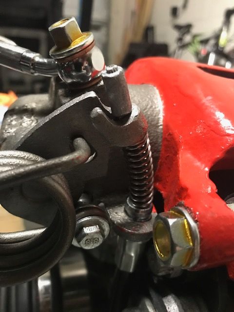
Finally, getting back to the brakes. I had some challenges getting the rear brakes bled initially. FFR sent me another MC, but once it was all completed, I don't think that was the issue. Again, AWESOME customer service. I did end up purchasing two new rear calipers, as the bleeding valves seemed to have excessive play and were leaking. I just got them on my own since FFR sent me the new MC. If anyone is looking for replacement rear calipers for the complete kit, they are from a 1987 or 1988 Thunderbird Sport Coupe. I now have a rock hard pedal for brakes and no leaks (Knock on wood). A couple of things I learned:
1. Per Edwardb's suggestion, pressure bleeding seems to be the best method over gravity and the 'push and hold' method. Because the front and rear MCs are in tandom, pressure bleeding allows you to do one corner at a time versus side to side.
2. When pressure bleeding, it may take multiple times for each corner. I would do one corner, then the next..seal it up, pump the brakes a few times, then repeat. I was surprised at how much air comes out even after two attempts.
3. I used the CNC pressure cap and small portable bike pump. I originally used a large bicycle pump and blew the tops off my MC reservoirs. Just too hard to control the pressure. The smaller one I got at Walmart (Schwinn Air Sport Pro) and you can operate with one hand with manageable pressure. It also allows you to twist the top on and off the reservoir without moving the pump. I would still keep one or two fingers on the MC top if you don't have it secured.


-
12-10-2018, 01:56 PM
#125
Originally Posted by
edwardb
Just to confirm, you have both sides of the pressed steel flanges flanges of the steering column bearing assembly on the outside of the footbox? It's not 100% clear from your picture. Just wanted to confirm you're not describing having one half inside and one half outside. That wouldn't capture the bearing properly.
Yes sir..that is correct. Both sides of the steel flanges are on the outside of the box. Thanks for checking on me Paul!
Last edited by cv2065; 12-10-2018 at 02:00 PM.
-
12-10-2018, 05:48 PM
#126
Glad you got your brake issues fixed. I've got the same problem with the rusting bolts on the pedal box. I'm going to be changing out mine as well. Ace Hardware, here I come!!!
-
12-10-2018, 09:11 PM
#127
Senior Member

Lookin' good!
Glad you got your brake issues resolved!
John D. - Minneapolis 'Burbs
1965 El Camino - LT-1, 4L60e, 4wh discs, SC&C susp.
2013 F-150 Platinum - Twin Turbo 3.5
2018 Mk4 Roadster w/ Coyote - #9365 - Build Thread Delivery 7/3/18, 1st Start 1/4/19, 1st Road Mile 5/5/19, Legal 6/18/19, In Paint 2/25/21, Done (?) 4/2021
-
12-25-2018, 12:34 PM
#128
-
Post Thanks / Like - 0 Thanks, 1 Likes
-
12-25-2018, 12:49 PM
#129
-
12-25-2018, 12:59 PM
#130
-
12-25-2018, 01:02 PM
#131
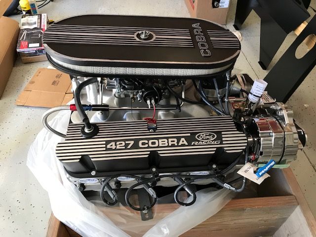
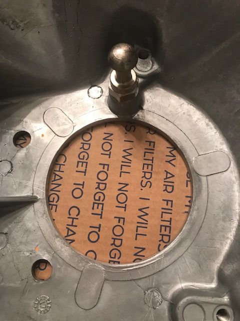
Beautiful! Here's a tip for you … don't forget to remove the exhaust port cover (stickers) before you follow BluePrint's oil priming directions. If you forget, the resulting POP POP POP will scare the poo out you!
-
12-25-2018, 01:06 PM
#132
I have the Mike Everson under dash panel. I had reviewed Gumball's thread a few years back as he notched it out for a few things, which I did the same then trimmed the sharp areas with wind lace. Came out very nicely. I will also install the USB port as well as the dimmer switch and windshield wiper toggle in this panel. I'm contemplating whether or not to use the supplied two support brackets from FFR in addition to the under dash panel for additional support. I'm sure it will be rock solid either way...
-
12-25-2018, 01:07 PM
#133
Originally Posted by
Papa
Beautiful! Here's a tip for you … don't forget to remove the exhaust port cover (stickers) before you follow BluePrint's oil priming directions. If you forget, the resulting POP POP POP will scare the poo out you!
LOL..Will do!! Thanks Dave!
-
12-25-2018, 03:48 PM
#134
Looking great.... Can't wait to hear that beast start.... Nice job on the floors...
-
12-27-2018, 08:21 PM
#135
I just ran across your build thread based off your signature. Your project is really coming along well. Good job. Looks like youll start it up soon.
build thread:
http://thefactoryfiveforum.com/showt...-USRRC-vspeeds
Build School: July 14-16, 2017
Kit purchased: July 25, 2017
Kit delivered: September 13, 2017
First Start: December 22, 2018
Body painted and kit completed and drivable: July 2019 (but still not done)
CA SB100 Registration: January 2020
Mk4 - 289 USRRC Roadster kit, Roush 427SR with Schneider Racing custom camshaft, Fitech EFI, TKO600 (.64-5th gear), 15" wheels, stock brake calipers, under car exhaust with Spintech 7000 muffler, no roll bar, Russ Thompson turn signal, removable steering wheel, and many other small upgrades and modifications
-
01-18-2019, 10:29 PM
#136
-
01-18-2019, 10:39 PM
#137
-
01-18-2019, 10:52 PM
#138
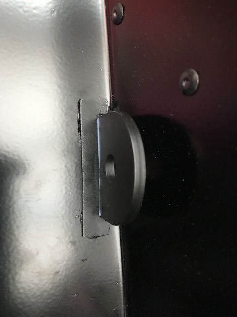
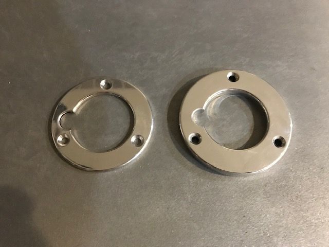
As I cut the larger steering shaft hole for my RT Turn Signal mod, the steering shaft trim piece that I bought for it was just slightly too small in circumference, where I could see some light coming through at the bottom. Had a good friend of mine duplicate the piece only larger and a little more robust. This guy taught me to weld and can duplicate just about anything. Props to my friend Steve!!
-
01-18-2019, 11:02 PM
#139
-
01-18-2019, 11:08 PM
#140
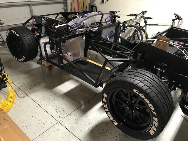
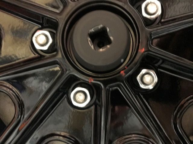
As she's on the ground now, decided to torque my rear IRS axle nuts. I had been putting this off until I could get some weight for the torque. I was able to easily achieve the 98 ft-lbs, but the 45 degree turn was a little more difficult. With a 25" breaker bar, I could only get to about 38-40 degrees. I'm going to drive it and see if anything settles. I'll try again for those last 5 degrees, but if nothing moves after driving, I'll leave as is and call it good. I will mark the position to ensure I can see if it moves.
-
01-18-2019, 11:09 PM
#141
Had a great conversation with Mr. Jeff Kleiner this week and am in line for his expert paint services. Nice talking with you Jeff. Look forward to working with you!
Last edited by cv2065; 01-19-2019 at 01:14 AM.
-
01-19-2019, 09:17 AM
#142
Senior Member

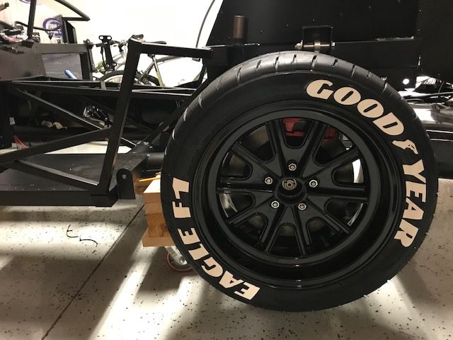
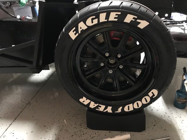
DuDe!! Your wheels and tires are smoking (are those tirestickers) !!! I just caught up on your thread, nice progress. Keep up the good work!! If ya don't mind me asking, what did it cost to get the wheels powder coated?
Last edited by Higgybulin; 01-19-2019 at 09:25 AM.
MK4 #11012 picked up 04/16/24
351W, 3 link, single roll bar
MK4 #10616 picked up 4/10/23
302w, 4 link, 17's, dual roll bar SOLD
MK4 #9759 picked up on 4/3/19
351C, 3 link, 17's, dual roll bars SOLD
-
01-19-2019, 09:35 AM
#143
Originally Posted by
HiggyMK4#????
DuDe!! Your wheels and tires are smoking (are those tirestickers) !!! I just caught up on your thread, nice progress. Keep up the good work!! If ya don't mind me asking, what did it cost to get the wheels powder coated?
Thanks Higgy. Yes, those are 1.5” tire stickers. Powder coating was $300 for all 4 wheels. I have a guy locally that is really reasonable and does a fantastic job.
-
Post Thanks / Like - 0 Thanks, 1 Likes
-
01-23-2019, 04:03 PM
#144
Nice progress. Good to see you coming along.
-
01-23-2019, 04:50 PM
#145
Not a waxer

Originally Posted by
cv2065
Had a great conversation with Mr. Jeff Kleiner this week and am in line for his expert paint services. Nice talking with you Jeff. Look forward to working with you!
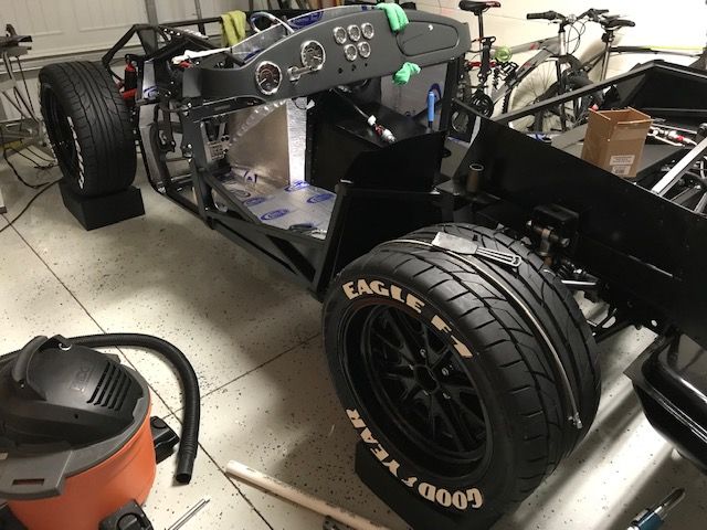
Nice to talk with you also Chad! Hey, you realize that your artificial Goodyears are on the wrong sides in the back, right?

Jeff
-
01-23-2019, 04:58 PM
#146
Originally Posted by
Jeff Kleiner
Nice to talk with you also Chad! Hey, you realize that your artificial Goodyears are on the wrong sides in the back, right?
Jeff
LOL...Good eye Jeff!! I had the fronts on the wrong side as well. Sigurd pointed that out when he was over. I'll get them swapped. I think I may have to get my readers adjusted again...
-
01-23-2019, 05:06 PM
#147
Either way, it's looking great....
-
02-02-2019, 08:53 AM
#148
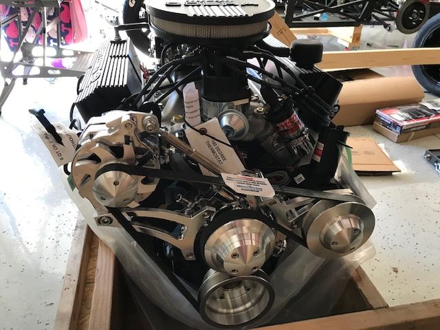
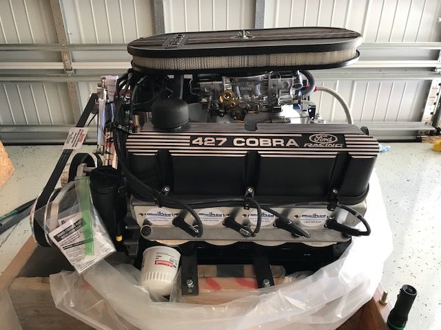
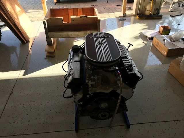
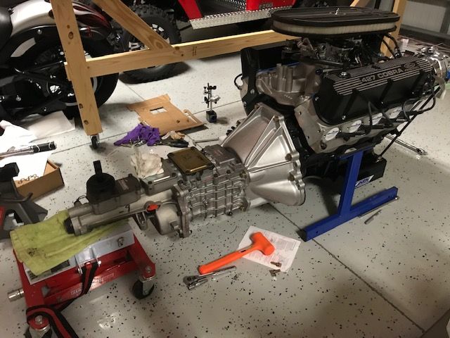
Engine Prep for Install
So after a few delays, finally getting my 427 situated for installation. I didn't pay to have my engine and trans mated, so that's where I'm starting.
First off, pilot bearing goes in. Nothing eventful here, just used a socket that matched the outside of the bearing and tapped it in. No freezer treatment or grease, just took my time and tapped it in. Very tight fit I will say. Compared to a Chevy bronze bushing which I've done in the past, I like these Ford roller bearings better when installing, as it has a lip around the edge of the bearing you use to tap it in and much harder to mushroom. I used the Ford M-7600-A pilot bearing.
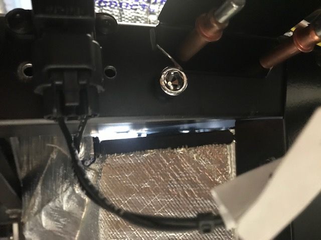
I then sprayed my starter index plate. That thing is steel and will rust if you look at it wrong. Had some Rustoleum oil based black semi gloss in the cabinet, and made it look like a million bucks.
Next, Flywheel goes on. Unfortunately, the first and second flywheels that I received were both from Speedmaster, and not high caliber products. I'd have to caution anyone buying this brand, as for a new flywheel sealed in the box, these left a lot to be desired as they were severely scratched, and in some cases, gouged. The alignment dowels were missing from the first box, and very basic with the second, so no good there either. I ordered a Ford Racing flywheel and it came perfect with quality alignment dowels. Tapped in the 3 dowels and then Installed with ARP flywheel bolts per their directions...Ready to roll. ARP recommends a little ARP Ultra torque assembly lube under the head of the bolt, Loctite 242 on the threads and torqued to 75 ft-lbs. I think many can forget, including myself, that the area under the head, not just the threads, can affect torque values as well.
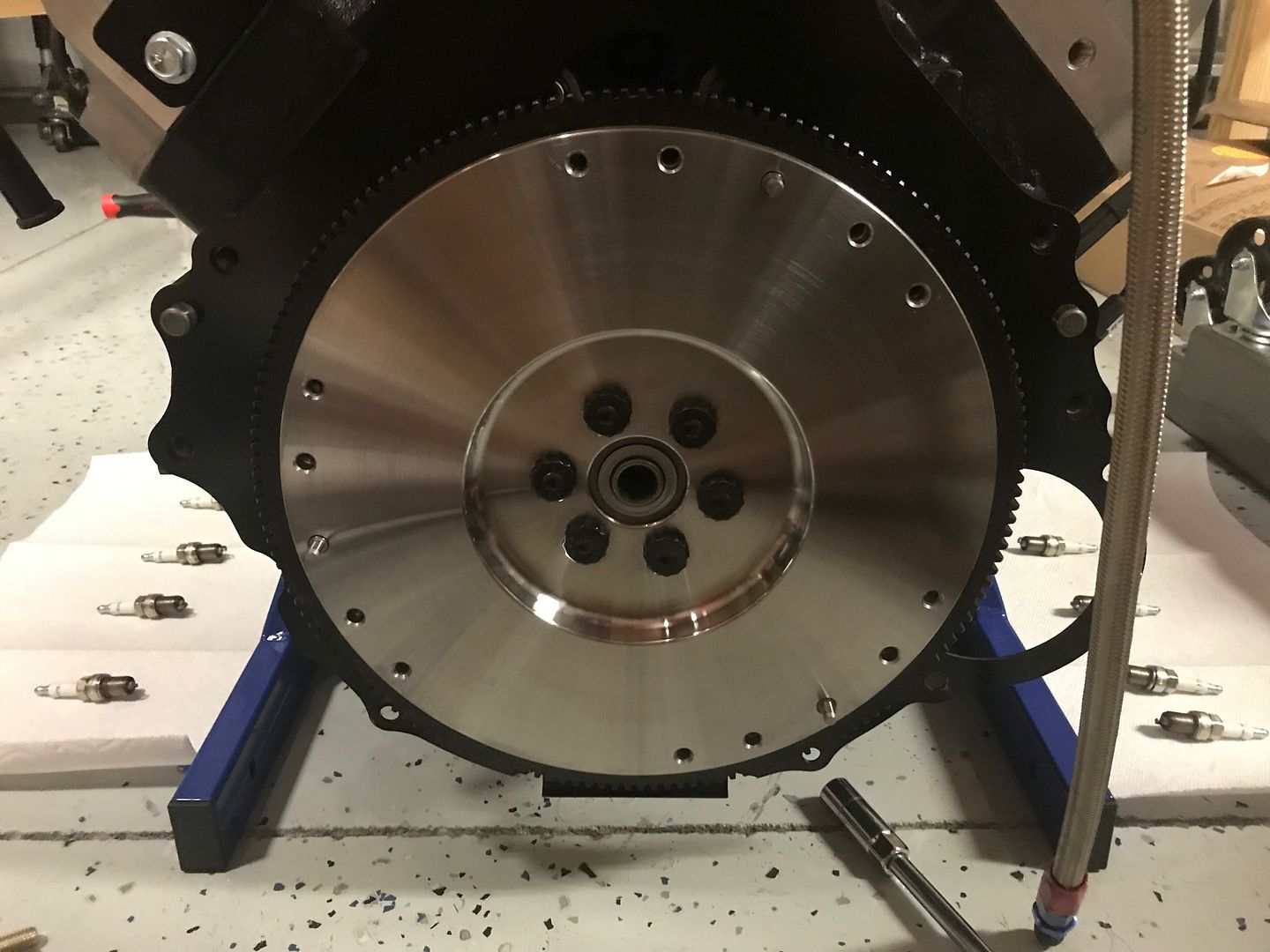
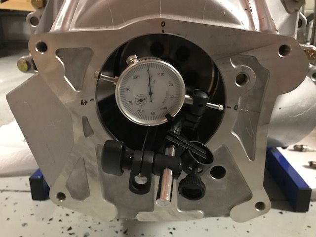
Once flywheel was on, I measured the bellhousing cocentricity. This has to be done before the clutch pressure plate is installed. My 13 year old son actually came out of his room to help me read the indicator while I was turning the crank. Nice!! I bought a dial indicator and base from Harbor Freight. I had to go through a couple of dial boxes to be sure that I got one that wasn't returned or jacked up. If I did this more often, I'd get one of higher caliber, but this did just fine. Bellhousing was good to go with readings of +4 at 90 degrees, +4 at 180 degrees, 0 at 270 degrees and 0 at 360 degrees (where I started). Measured twice for reading accuracy and the bell is very 'concentric'. 
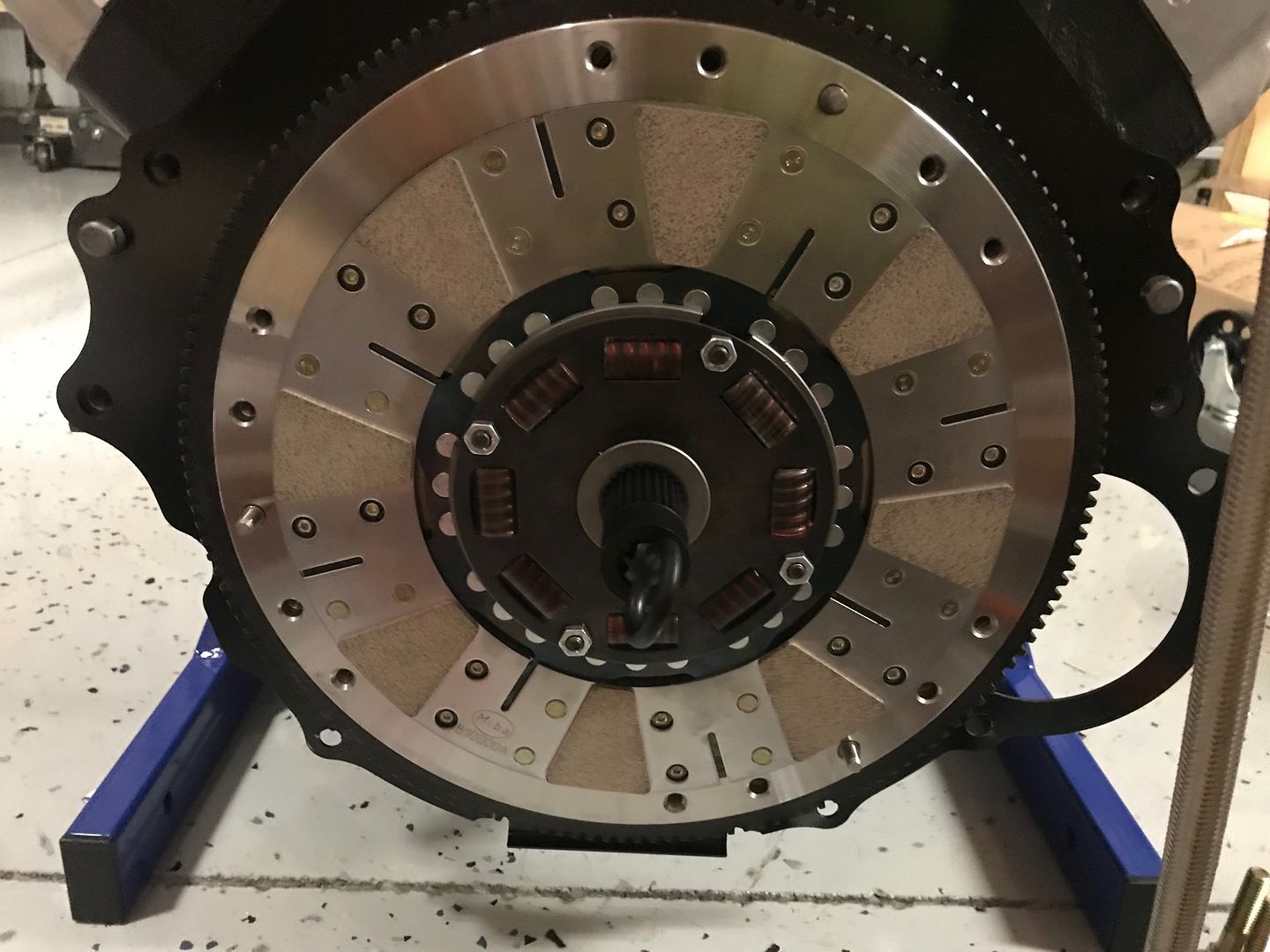
Clutch disc went on next. My clutch kit is the RAM 98794T. As I installed the clutch disc, it did not have any designation which side faced which, so asked Mike Forte and was good to go. As I learned, the flat side of the disc, 99% of the time, goes towards the engine, and the protruding side goes towards the trans. Used the alignment tool and on it went.
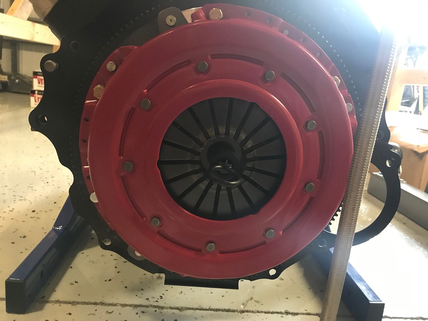
Pressure Plate now goes on and aligned with the flywheel dowels and secured without a hitch. I will say that the first time I tightened down, I was tightening in a star pattern, but might have had a little more turns on one side versus the other, as the fingers of the pressure plate were a little uneven. This can cause vibration, so loosened them up again and made sure that I had the same amount of turns on every bolt as I tightened them up. Fingers were perfect and ready to roll. I used Loctite 242 (blue) on all of my threads with lock washers and M8-1.25 (10.9) bolts at 25 ft-lbs. Maybe a little overkill, but my pressure plate won't be flying off anytime soon.
Last edited by cv2065; 02-02-2019 at 09:43 AM.
-
02-02-2019, 09:33 AM
#149
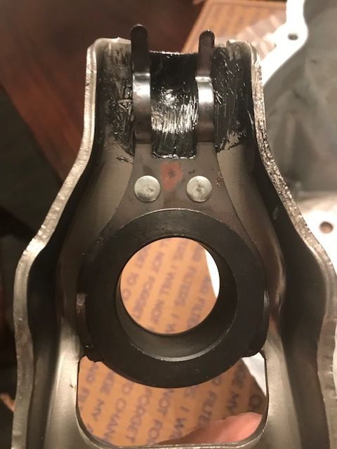
Bellhousing prep was next. If you look at these Bells from Ford, I have the M-6392-R58 for a Tremec trans, they have a pretty rough casting. So much to the point, where you could cut your finger if not careful. I compared to another Ford unit and it was exactly the same. Forte also confirmed that this is uniform with all of their Bells, so just smoothed out the casting a little bit and moved on. installed the clutch fork pivot pin that came with the bellhousing with a little loctite. Hard to get any kind of torque wrench on it, so used the German "Goodentite" method.
Prepared the clutch fork (E6ZR-7515-AA) with a little grease. Ford gets a little carried away here with the moly grease. I wiped it and went back in with my grease of choice, which is the Lucas X-Tra Heavy Duty (green). The grease Ford uses on their pilot and TOB are also green. Wonder if its the same? Anyway, important not to mix greases so started fresh all the way around. One thing to note is that the Ford clutch fork I've listed is the 'engineering' number. So if you order one and the outside of the box says E6ZZ...it's the same fork.
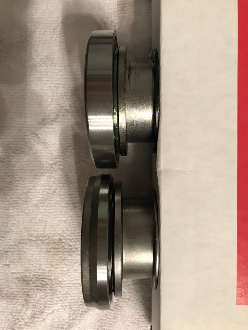
I didn't use the TOB that came with the RAM clutch as many have suggested on the forum. So I went with the Ford Racing M-7548-A. Definitely a quality difference here. I took a picture of both so one could compare. The Ford bearing is on the bottom and RAM bearing on the top. There is a distinct difference where the clutch fork installs on the bearing, as the Ford surface area here is much larger than the RAM. Both pieces seemed to be similar in weight and construction.
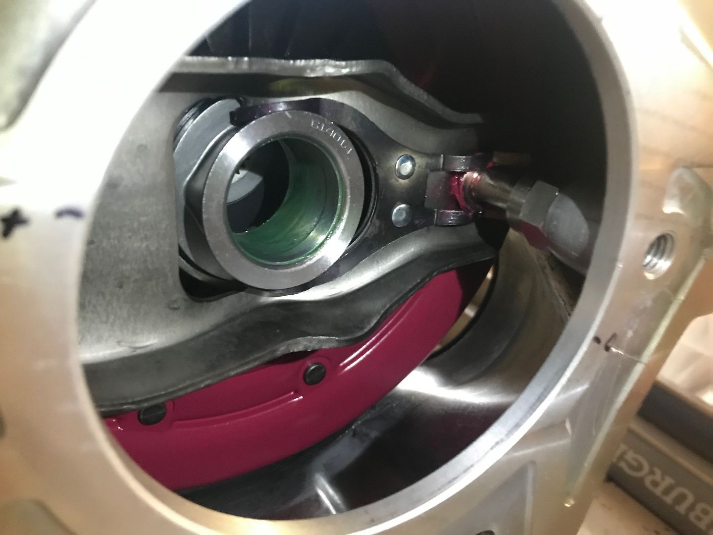
I made sure that the clutch fork prongs secured underneath the lip of the TOB, and not on top. I've read that's a common mistake and will cause one to have to disassemble...Not fun. Here's the clutch fork and TOB installed in the bellhousing. A thin coating of Lucas green inside the TOB, as well as a thin coat on the outside lip of the TOB where it will contact the clutch fingers and some on the clutch fork pivot ball. You can see red grease here on the pivot ball area which is Lucas Red Tacky. There's a grease for everything!
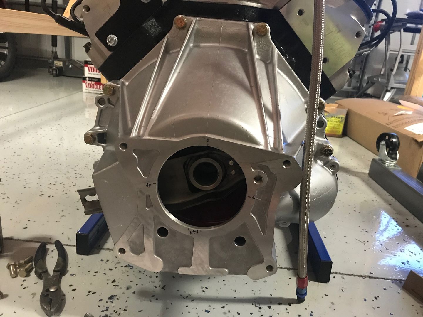
I sprayed the bellhousing with some Silver epoxy that I had and looks great. Installed the bell with lockwashers at 45 ft-lbs for the larger bolts and 25 ft-lbs for the 2 smaller 5/16". All grade 8 of course.
Next up is the starter and trans.
Last edited by cv2065; 02-02-2019 at 09:46 AM.
-
02-02-2019, 01:43 PM
#150
Looking Great Chad.... Very nice write up....
-
02-02-2019, 03:00 PM
#151
Senior Member
Little heavy on the grease there IMO. Especially on the inside of the TOB that goes on the input shaft. I put a little there but you can barely see it. Don't see how much you put on the face of the TOB. That too should be so light you can barely see it. You really don't want that stuff flinging around in there. See that you locked down the adjustable pivot. Where did your clutch arm end up with the TOB resting against the clutch pressure plate fingers? It should be roughly perpendicular to the output shaft. Typically slightly toward the back of the opening in the bell housing. It's pretty normal to have to take the bell housing off and on a couple times to get the pivot in the right spot.
Build 1: Mk3 Roadster #5125. Sold 11/08/2014.
Build 2: Mk4 Roadster #7750. Sold 04/10/2017.
Build Thread
Build 3: Mk4 Roadster 20th Anniversary #8674. Sold 09/07/2020.
Build Thread and
Video.
Build 4: Gen 3 Type 65 Coupe #59. Gen 3 Coyote. Legal 03/04/2020.
Build Thread and
Video
Build 5: 35 Hot Rod Truck #138. LS3 and 4L65E auto. Rcvd 01/05/2021. Legal 04/20/2023.
Build Thread. Sold 11/9/2023.
-
02-02-2019, 03:08 PM
#152
Originally Posted by
edwardb
Little heavy on the grease there IMO. Especially on the inside of the TOB that goes on the input shaft. I put a little there but you can barely see it. Don't see how much you put on the face of the TOB. That too should be so light you can barely see it. You really don't want that stuff flinging around in there. See that you locked down the adjustable pivot. Where did your clutch arm end up with the TOB resting against the clutch pressure plate fingers? It should be roughly perpendicular to the output shaft. Typically slightly toward the back of the opening in the bell housing. It's pretty normal to have to take the bell housing off and on a couple times to get the pivot in the right spot.
Thanks for the feedback Paul. The grease is pretty thin on both accounts, but I can revisit easily enough. Regarding pivot ball, the one that came with the bell is fixed and not adjustable. I haven’t hooked up the hydraulic unit yet, so not sure exactly how it will all sit but doesn’t look like the stock pivot ball gives options.
-
02-02-2019, 03:39 PM
#153
Senior Member
Originally Posted by
cv2065
Thanks for the feedback Paul. The grease is pretty thin on both accounts, but I can revisit easily enough. Regarding pivot ball, the one that came with the bell is fixed and not adjustable. I haven’t hooked up the hydraulic unit yet, so not sure exactly how it will all sit but doesn’t look like the stock pivot ball gives options.
Oops. Forgot the stock bell pivot is fixed. You should be OK, but cable or hydraulic doesn't matter. The clutch arm has to be in the proper location to have the right leverage and available movement.
Build 1: Mk3 Roadster #5125. Sold 11/08/2014.
Build 2: Mk4 Roadster #7750. Sold 04/10/2017.
Build Thread
Build 3: Mk4 Roadster 20th Anniversary #8674. Sold 09/07/2020.
Build Thread and
Video.
Build 4: Gen 3 Type 65 Coupe #59. Gen 3 Coyote. Legal 03/04/2020.
Build Thread and
Video
Build 5: 35 Hot Rod Truck #138. LS3 and 4L65E auto. Rcvd 01/05/2021. Legal 04/20/2023.
Build Thread. Sold 11/9/2023.
-
02-02-2019, 03:52 PM
#154
Originally Posted by
edwardb
Oops. Forgot the stock bell pivot is fixed. You should be OK, but cable or hydraulic doesn't matter. The clutch arm has to be in the proper location to have the right leverage and available movement.
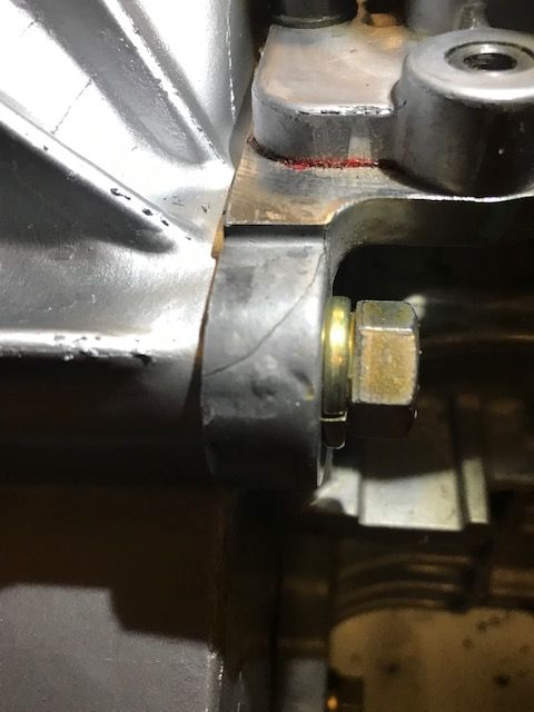
All good Paul. Thanks for reminding me to check that. Looks perfectly perpendicular to where the input shaft will go when the TOB is just touching the clutch fingers, with the end of the arm slightly towards the back of the bellhousing. Not sure if this picture shows it too well, but I think we are good to go!
-
02-03-2019, 11:40 PM
#155
-
Post Thanks / Like - 0 Thanks, 1 Likes
-
02-04-2019, 07:46 AM
#156
Senior Member
Originally Posted by
cv2065
What's the best way of 'testing' a transmission install to make sure everything is seated while the engine/trans is still out of the car? Thought of just pulling the spark plugs and rotating at the crank to see how it all feels.
You could. But honestly with it together like that, and given that all the pieces you're using are pretty standard and well proven, very unlikely anything is wrong. With it in gear and the plugs pulled, should turn over easy enough and the trans output shaft turn. Beyond that, the only other unknown is that your starter aligns properly. But with a standard bell, flywheel, etc. should be fine if it bolts in correctly. On both Forte hydraulic clutch setups I've done I plumbed them up and tested before installing the engine. This after a buddy of mine had his in/out several times getting everything just right. But it's kind of a pain, and potentially messy. Assume you know the pushrod Forte supplies has to be cut to the proper length. With that, the other wildcard is the master cylinder. Some have had issues with overdriving the slave. Even to the point of popping it out. Not good. Addressed by either adding a clutch stop or a smaller master cylinder.
Build 1: Mk3 Roadster #5125. Sold 11/08/2014.
Build 2: Mk4 Roadster #7750. Sold 04/10/2017.
Build Thread
Build 3: Mk4 Roadster 20th Anniversary #8674. Sold 09/07/2020.
Build Thread and
Video.
Build 4: Gen 3 Type 65 Coupe #59. Gen 3 Coyote. Legal 03/04/2020.
Build Thread and
Video
Build 5: 35 Hot Rod Truck #138. LS3 and 4L65E auto. Rcvd 01/05/2021. Legal 04/20/2023.
Build Thread. Sold 11/9/2023.
-
02-04-2019, 08:28 AM
#157
Originally Posted by
edwardb
You could. But honestly with it together like that, and given that all the pieces you're using are pretty standard and well proven, very unlikely anything is wrong. With it in gear and the plugs pulled, should turn over easy enough and the trans output shaft turn. Beyond that, the only other unknown is that your starter aligns properly. But with a standard bell, flywheel, etc. should be fine if it bolts in correctly. On both Forte hydraulic clutch setups I've done I plumbed them up and tested before installing the engine. This after a buddy of mine had his in/out several times getting everything just right. But it's kind of a pain, and potentially messy. Assume you know the pushrod Forte supplies has to be cut to the proper length. With that, the other wildcard is the master cylinder. Some have had issues with overdriving the slave. Even to the point of popping it out. Not good. Addressed by either adding a clutch stop or a smaller master cylinder.
Thanks Paul. I've read your build thread on changing out the MC on the Forte clutch. Might be good insurance to do ahead of time.
-
02-04-2019, 09:11 AM
#158
Not a waxer
No need to attempt to turn the engine over. Put the trans in gear and try to turn the output shaft...it doesnt, right? Leave it in gear, move the throwout lever as if the clutch pedal was being depressed...now the output shaft can be turned, right? If yes on both counts stab the whole works in the chassis!
Jeff
-
02-04-2019, 10:14 AM
#159
Senior Member
Originally Posted by
cv2065
Thanks Paul. I've read your build thread on changing out the MC on the Forte clutch. Might be good insurance to do ahead of time.
Another size MC might be a better fit, as I found. But there are variables. I'd start with the one you have and see how it works. Easy enough to change at this stage if that's the best alternative.
Build 1: Mk3 Roadster #5125. Sold 11/08/2014.
Build 2: Mk4 Roadster #7750. Sold 04/10/2017.
Build Thread
Build 3: Mk4 Roadster 20th Anniversary #8674. Sold 09/07/2020.
Build Thread and
Video.
Build 4: Gen 3 Type 65 Coupe #59. Gen 3 Coyote. Legal 03/04/2020.
Build Thread and
Video
Build 5: 35 Hot Rod Truck #138. LS3 and 4L65E auto. Rcvd 01/05/2021. Legal 04/20/2023.
Build Thread. Sold 11/9/2023.
-
02-09-2019, 10:40 PM
#160
Originally Posted by
Jeff Kleiner
No need to attempt to turn the engine over. Put the trans in gear and try to turn the output shaft...it doesnt, right? Leave it in gear, move the throwout lever as if the clutch pedal was being depressed...now the output shaft can be turned, right? If yes on both counts stab the whole works in the chassis!
Jeff
Looks like everything moves as it should Jeff. Thanks for the tips!
-
Post Thanks / Like - 0 Thanks, 1 Likes


 Thanks:
  Likes:


 Reply With Quote