PLEASE REVIEW POST 44 IN THIS THREAD IF YOU PLAN TO BUILD THIS YOURSELF FROM MY DRAWINGS.
I build a lot of things instead of buying - within reason, and then sometimes without reason. I just like doing a lot of different things in a project. It's why I'm building an 818 - to do instead of buying "done".
These days a lot of people who would never get into electronics, are doing so, with just a little info to get them going. This is not really a complex circuit by any means. If you have just a bit of skill, or an 'electronics type' friend who wants to help, or even a high-school kid who wants to learn and try it - I say go for it.
I haven't done a PCB board for this yet but will, and will post up a drawing for that. It can be done just on a piece of perf board, etc. for that matter.
I did the breadboard setup and tests, with several of the LED lights listed below, from Amazon. Also verified it works with the standard Subaru 3 terminal flasher module, with LED's. (in the olden days flasher modules often needed the "load" of incandescent lamps to do the flashing - hence I tested it). This would get in trouble running incandescent bulbs, or LED's drawing much over a total of 300mA (Q1 would get HOT at least if not fail).
Other transistors (must be reasonably equivalent in characteristics to these) can be used, these are the ones I had in my junk boxes.
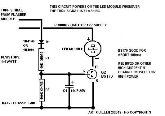
How it works:
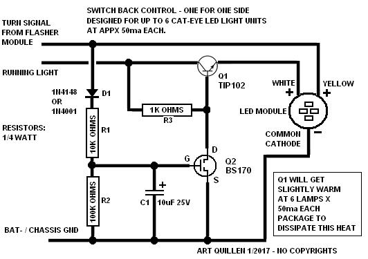
With "turn signal off", Q2 is off, allowing Q1 to turn on. This lights the white LED's connected to Q1. When turn signal is energized, the Yellow LED's light by direct wiring through the flasher 12V. Also this turn signal 12V almost instantly charges capacitor C1 via diode D1 and low ohms resistor R1. The 12V at C1 and the gate of Q2 turns on Q2. Q2 turns off Q1 so the white LED's are turned off instantly.
Once the turn signal is off, the high resistance in R2 begins to discharge C1. The resistance/capacitance time constant of R2, C1 takes about 2 seconds to discharge enough that Q2 can turn off. By this time a blinking turn signal has recharged C1 repeatedly so Q2 remains turned on. After the blink condition ends, C1 will finally be able to discharge until Q2 turns off, allowing Q1 to turn back on and resume the running white LED mode.
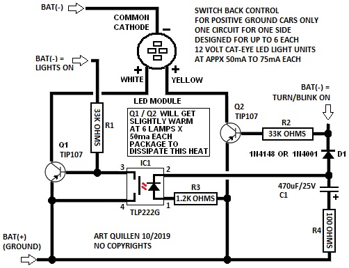
With 6 each of some 50 milli-ampere white LED's connected to Q1 it can get slightly warm, so packaging of the circuit (pot in epoxy for example), should be such that it can dissipate some heat, about 1/4 to 1/2 watt is typical. Also the Q1 transistor case must be insulated from ground, etc.
The LED's I tried were pointed out in another post here, I bought them and like them. Yes tiny wires, but that is all they need for the current demand in play.
One way to package this might be in an Altoids box, or a cigar tube, then pot (filled) the container with some JB Weld. I believe JB Weld has metal filler but not to the point of being conductive enough to affect this circuit. The Q1 should be close to the surface of the container so it can pass heat out, but not touching. JB will move the heat out fairly well. If you get to fancy it finally reaches the point where buying a couple commercial modules would make more sense. But then you didn't build it yourself (818 wink).
https://www.amazon.com/gp/product/B0...?ie=UTF8&psc=1
If the link to the site goes bad, here is what they were described in the ad:
Everbright 8-Pack White / Amber Switchback 12V 9W Eagle Eye Lamp Led Light Bulbs For Car Tail Car Motor Backup Light Fog Light Daytime Running Lights(DRL)


 Thanks:
  Likes:


 Reply With Quote