-
10-06-2022, 05:22 PM
#521
Had a member of the Upstate Cobra Club stop by. As I noted the diff was at a -.8 degree angle. We raised the transmission until the transmission and cross brace lined up. Needed 3/8" worth of washers between the cross brace and the transmission mount. This gave me a +.8 on the drive shaft angle and a +2.4 degrees on the transmission. Locked it down there.
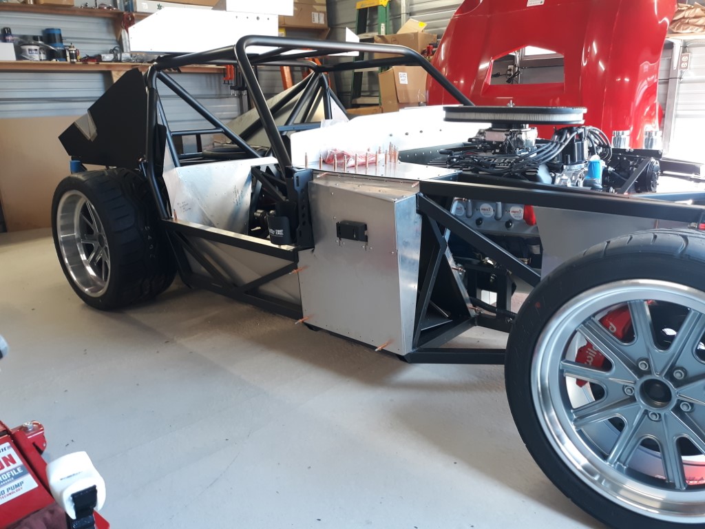
Mounted the wheels and dropped it off the jack stands. Officially a roller!!
-
Post Thanks / Like - 0 Thanks, 1 Likes
-
10-06-2022, 10:31 PM
#522
Another option would be engine drop mounts. Mounts that drop the engine 3/4" after common parts. In your case it would help the situation, and also help your soon to be hood clearance issue. Potential exhaust fitment issues unknown.
-
10-07-2022, 06:47 AM
#523
You want the transmission output shaft angle and the differential yoke to be parallel to each other with a slight angle (2 degrees is good enough for this short driveshaft) of the drive shaft. The drive shaft angle can be in any direction.
My Type 65 Coupe: Ordered May 27, 2021. Arrived November 19, 2021.
I would like to treat my gas pedal as a binary operator. It would be nice to get the cooperation of everyone in front of me. 
-
10-07-2022, 07:31 AM
#524

Originally Posted by
GT_Rich

Another option would be engine drop mounts. Mounts that drop the engine 3/4" after common parts. In your case it would help the situation, and also help your soon to be hood clearance issue. Potential exhaust fitment issues unknown.
Dropping the engine would create different issues. My oil pan and the bottom of the transmission would then be below the frame.
-
10-07-2022, 07:36 AM
#525


Originally Posted by
Skuzzy

You want the transmission output shaft angle and the differential yoke to be parallel to each other with a slight angle (2 degrees is good enough for this short driveshaft) of the drive shaft. The drive shaft angle can be in any direction.
I am not the first to use a SBF in this car. I would guess I'm not the first to use the TKX either. There is simply no way to line up the shafts . There is a very small box of adjustments available to install and make everything fit. FF confirmed that I have the right parts. If there were major issue with the fitment of this combination the way I have it I'm sure it would have been noted long ago. These are FF parts not donor parts so I now have faith that it is a non issue now that everything fits except for the parallel shafts. Local builders have looked at it and have given it their blessing. Given the fact that the diff is fixed in place and can't move I'm still not convinced that they have to be. Once it's on the road I will know if I have any vibration or not. I know the TKX is new but from what I've been told it's the same, dimension wise, to the TKO when it comes to mounting. If anyone else out there has used a 351 with the TKX please chime in and let us know what you did.
-
10-07-2022, 07:56 AM
#526
I am somewhat close to installing my 427/TKX combo. I have the same Champ pan that you have. I bought the pan and drop mounts from Gordon Levy and he promised the pan would sit about the frame rails. Would you mind putting a straight edge across the bottom of your chassis and measure up to the pan with standard mounts in place?
I think your compromise on angles is pretty good.
-
10-07-2022, 09:23 AM
#527

Originally Posted by
GT_Rich

I am somewhat close to installing my 427/TKX combo. I have the same Champ pan that you have. I bought the pan and drop mounts from Gordon Levy and he promised the pan would sit about the frame rails. Would you mind putting a straight edge across the bottom of your chassis and measure up to the pan with standard mounts in place?
I think your compromise on angles is pretty good.
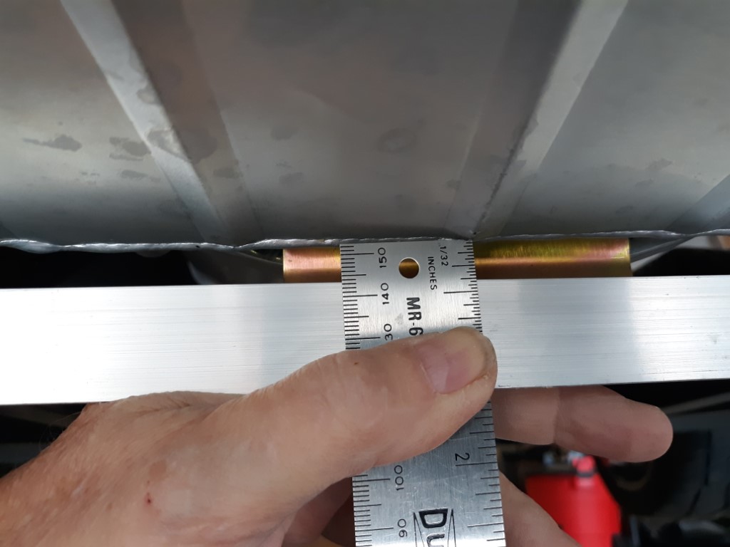
As my engine sits right now the clearance on the pan is 3/8".
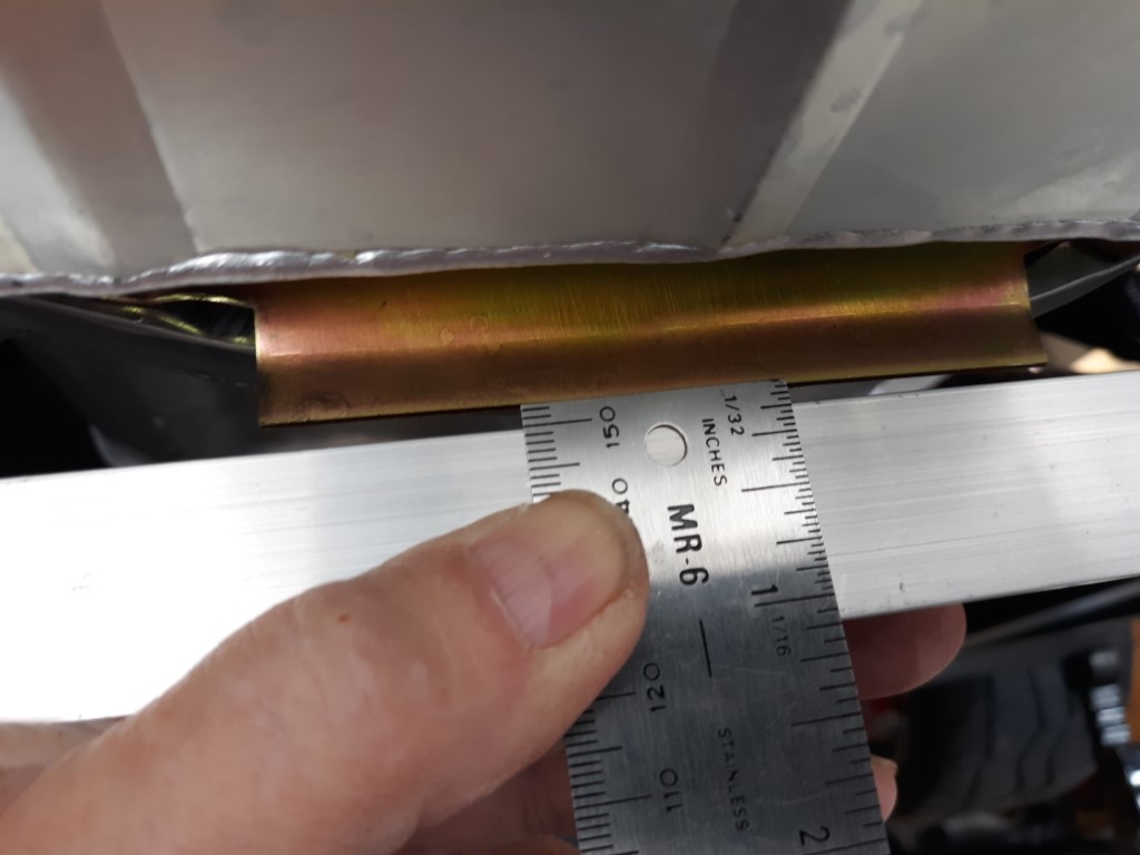
The clearance on the spacer plate for the tranny is 1/8".
-
Post Thanks / Like - 1 Thanks, 0 Likes
-
10-07-2022, 11:36 AM
#528
Thanks for the pics! That is not the result Gordon advertised to me when he sold me these parts. It looks like I will need to either shim up the solid drop mounts or go to the FFR provided option.
-
10-13-2022, 05:11 PM
#529
Day 112 progress walk around
112 days post delivery. Working to get to a point I can attempt first start. Biggest holdup is headers. No word on these. Wiring is 70% laid out. Sniper is laid out. Radiator mocked up and plumbed. (Love the look of the cool tubes) Mike Forte sent the power steering reservoir. Should be here tomorrow. Laid out switch location on the dash.
https://youtu.be/GxkdGbnaNwQ
-
10-13-2022, 05:31 PM
#530
Senior Member

Looking good. You're doing a great job. I know some of your wiring and such isn't finalized. But one observation. Make sure to get that front crossover convolute further away from your upper radiator tube. That tube gets very hot of course, and some convolute has a (disappointingly IMO) low melting point. Good luck with the upcoming first start. It's a huge milestone and quite exciting.
Build 1: Mk3 Roadster #5125. Sold 11/08/2014.
Build 2: Mk4 Roadster #7750. Sold 04/10/2017.
Build Thread
Build 3: Mk4 Roadster 20th Anniversary #8674. Sold 09/07/2020.
Build Thread and
Video.
Build 4: Gen 3 Type 65 Coupe #59. Gen 3 Coyote. Legal 03/04/2020.
Build Thread and
Video
Build 5: 35 Hot Rod Truck #138. LS3 and 4L65E auto. Rcvd 01/05/2021. Legal 04/20/2023.
Build Thread. Sold 11/9/2023.
-
10-13-2022, 05:49 PM
#531
-
10-13-2022, 05:50 PM
#532

Originally Posted by
edwardb

Looking good. You're doing a great job. I know some of your wiring and such isn't finalized. But one observation. Make sure to get that front crossover convolute further away from your upper radiator tube. That tube gets very hot of course, and some convolute has a (disappointingly IMO) low melting point. Good luck with the upcoming first start. It's a huge milestone and quite exciting.
Thanks for that little tid-bit! Will fix that.
-
10-13-2022, 06:25 PM
#533

Originally Posted by
Namrups

Added a pressure gauge to the fuel feed line.
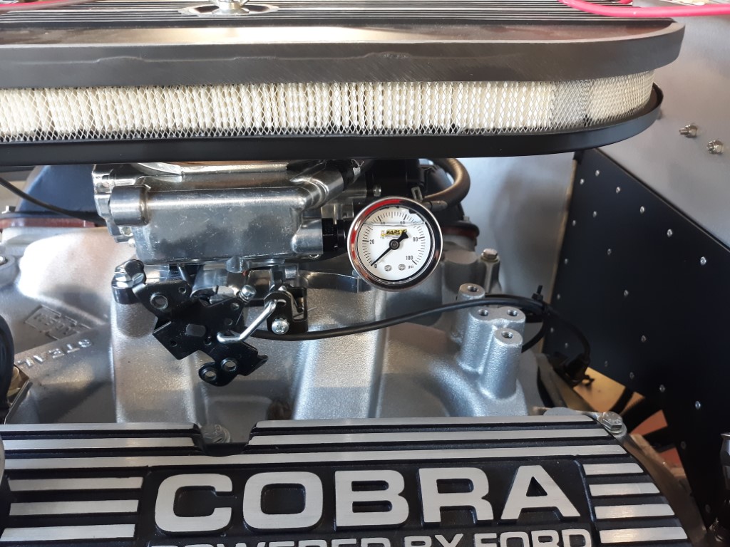
I have a couple of questions....
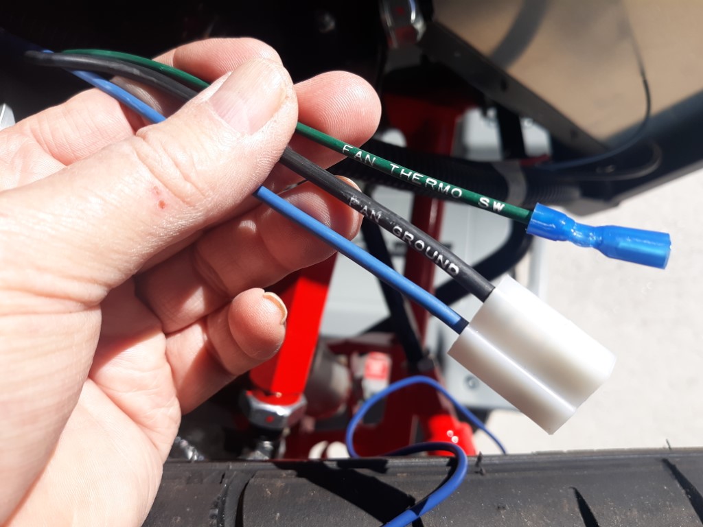
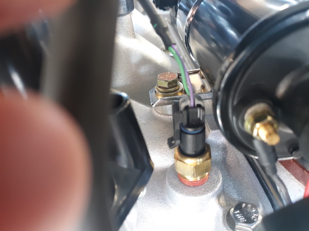
The RT fan wiring connection did not fit the fan connection. I rewired it with a weatherproof connector. There was also a third wire labeled "fan thermo sw". I believe this is a water temp sensor. The Sniper already has a temp sensor so do I need this one? I terminated it but left it in place. My next question is can I tap into the Sniper temp sensor to run my water temperature gauge or do I have to have a second separate sensor for the temp gauge?
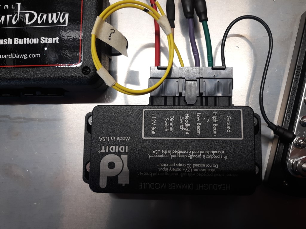
On the Ididit headlight dimmer unit, can someone verify for me that the yellow wire, labeled "headlight switch, needs to be mated to the brown dimmer switch wire. The RT diagrams do not show it that way but the diagram I downloaded for the Ididit site does.
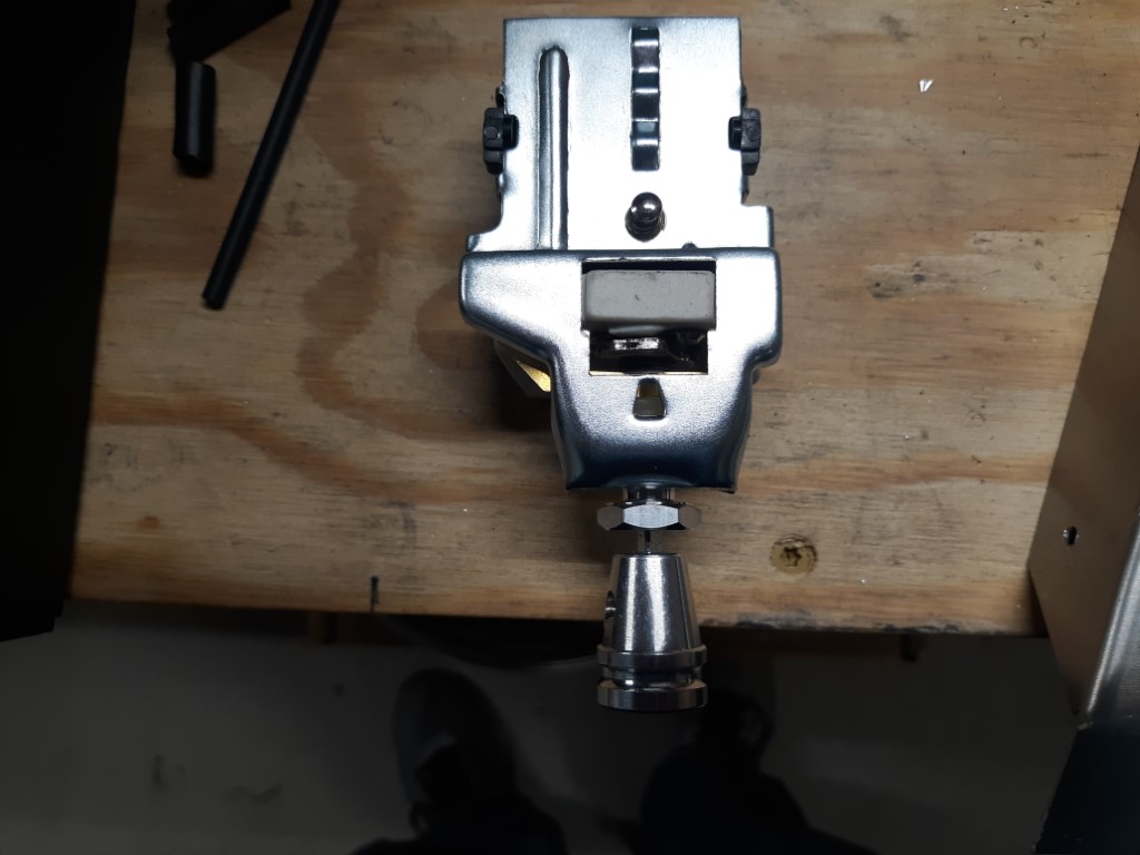
Last question for today... I feel silly asking but ... How do I get the shaft to pull out of the headlight switch so that I can mount the switch? I tried pressing the spring button but nothing happened. I tried to undo the set screw but that didn't help either. I didn't want to put to much force on either not knowing the right procedure.
I had the same question about the temp sensor, I am running an Atomic 2 efi
-
10-13-2022, 07:37 PM
#534
Not a waxer

Scott,
Pressing the little tab/button with the spring will allow you to pull the knob and shaft from the switch---but they aren't exactly a precision piece of machinery so it may take some wiggling and colorful language along with button pushing.
Use that fuel pressure gauge for your initial setup and tuning but please don't leave it in place long term. Those things are notorious for rupturing and have been responsible for a whole bunch of cars (including more than one FFR) burning to the ground.
Jeff
-
10-13-2022, 07:44 PM
#535
This video from Ron Francis may be helpful for the headlight switch. They're definitely not a precision piece of equipment and will require some creative wiggling/swearing to take apart.
MkIV Roadster build: Gen 2 Coyote, IRS, TKO600. Ordered 10/24/18. Delivered 1/29/19. Engine installed 8/8/21. First start 9/12/21. First go-kart 9/17/21. Off to paint 4/11/22. Back from paint 12/30/22.
Build thread here.
-
10-13-2022, 08:54 PM
#536

Originally Posted by
Jeff Kleiner

Scott,
Pressing the little tab/button with the spring will allow you to pull the knob and shaft from the switch---but they aren't exactly a precision piece of machinery so it may take some wiggling and colorful language along with button pushing.
Use that fuel pressure gauge for your initial setup and tuning but please don't leave it in place long term. Those things are notorious for rupturing and have been responsible for a whole bunch of cars (including more than one FFR) burning to the ground.
Jeff
Thanks Jeff. I will keep trying. Thanks for reminding me about the gauge. I had read that somewhere. At my "advanced" age it's always good to get the memory banks tickled. I will note it on my white board.
-
10-13-2022, 08:54 PM
#537

Originally Posted by
JohnK

This video from Ron Francis may be helpful for the headlight switch. They're definitely not a precision piece of equipment and will require some creative wiggling/swearing to take apart.
Helpful video! Thanks John.
-
10-14-2022, 06:04 AM
#538
Senior Member


Originally Posted by
Namrups

I have a couple of questions....
The RT fan wiring connection did not fit the fan connection. I rewired it with a weatherproof connector. There was also a third wire labeled "fan thermo sw". I believe this is a water temp sensor. The Sniper already has a temp sensor so do I need this one? I terminated it but left it in place. My next question is can I tap into the Sniper temp sensor to run my water temperature gauge or do I have to have a second separate sensor for the temp gauge?


On the Ididit headlight dimmer unit, can someone verify for me that the yellow wire, labeled "headlight switch, needs to be mated to the brown dimmer switch wire. The RT diagrams do not show it that way but the diagram I downloaded for the Ididit site does.

Can't answer a specific Sniper question (haven't installed one) but the "fan thermo sw" wire in the RF harness when grounded activates the fan relay in the RF panel which in turn powers the +12V feed to the cooling fan. Most temp senders close to ground when they reach their rated temperature, which turns on the fan.
For the Ididit headlight relay, that yellow wire has to go to a +12V feed from your headlight switch that's on when the headlight switch is on. Per my build notes, I wired to the RF harness LT BLUE HDLT SW -> DIM SW wire. It's purpose is to tell the module the headlight switch is on, so power the headlights on all the time and the dimmer signal switches from low to high. As opposed to no +12V on the yellow wire, which means the headlight switch is off and pressing the dimmer button activates the flash-to-pass function.
Build 1: Mk3 Roadster #5125. Sold 11/08/2014.
Build 2: Mk4 Roadster #7750. Sold 04/10/2017.
Build Thread
Build 3: Mk4 Roadster 20th Anniversary #8674. Sold 09/07/2020.
Build Thread and
Video.
Build 4: Gen 3 Type 65 Coupe #59. Gen 3 Coyote. Legal 03/04/2020.
Build Thread and
Video
Build 5: 35 Hot Rod Truck #138. LS3 and 4L65E auto. Rcvd 01/05/2021. Legal 04/20/2023.
Build Thread. Sold 11/9/2023.
-
10-14-2022, 06:21 AM
#539
Just watched your walk around video. Looking good. A couple questions related to aluminum panels. I thought the tall panels in the back corner of the cockpit had to be installed after the body was in place? You have them riveted now. Have you trialed that? Other question is related to the back aluminum upright panels (on the right side, it has the recess for fuel fill)...do people rivet thse to the down tubes on the chassis? If not, does the body pull them away from the tubes or does some type of gasket material need to go between tubes and panel?
-
10-14-2022, 08:21 AM
#540


Originally Posted by
GT_Rich

Just watched your walk around video. Looking good. A couple questions related to aluminum panels. I thought the tall panels in the back corner of the cockpit had to be installed after the body was in place? You have them riveted now. Have you trialed that? Other question is related to the back aluminum upright panels (on the right side, it has the recess for fuel fill)...do people rivet thse to the down tubes on the chassis? If not, does the body pull them away from the tubes or does some type of gasket material need to go between tubes and panel?
Two very good questions. I do not know the "right" answer for either one. All of these panels were in the car when it arrived and the body was removed with them in place. I am figuring that if I could remove the body with them in place I can replace the body with them in place. It may mean more than one try to mount the body if there is any trimming involved. Only time will tell.
I did not rivet the side panels to the down tube. There will be bulb seal on the top edge that should conform to the body so the body will dictate how the panels fit along the top edge.
I ask any previous builders to chime in here and give us both a heads up on how this all works.
-
10-14-2022, 08:32 AM
#541


Originally Posted by
edwardb

Can't answer a specific Sniper question (haven't installed one) but the "fan thermo sw" wire in the RF harness when grounded activates the fan relay in the RF panel which in turn powers the +12V feed to the cooling fan. Most temp senders close to ground when they reach their rated temperature, which turns on the fan.
For the Ididit headlight relay, that yellow wire has to go to a +12V feed from your headlight switch that's on when the headlight switch is on. Per my build notes, I wired to the RF harness LT BLUE HDLT SW -> DIM SW wire. It's purpose is to tell the module the headlight switch is on, so power the headlights on all the time and the dimmer signal switches from low to high. As opposed to no +12V on the yellow wire, which means the headlight switch is off and pressing the dimmer button activates the flash-to-pass function.
Thanks for your info on the Ididit switch. As for the fan thermo switch, if i'm understanding this, it needs to be attached to a temperature sensor located in the radiator so when the temperature of the water in the radiator reaches a certain level the fan comes on. I need to figure out how to wire that so that it works with the fan control of the Sniper. Any Sniper experts out there?
-
10-14-2022, 08:47 AM
#542
Thanks for the reply. I follow your logic and my logic has been similar. However, my kit arrived without the cockpit corner panels. Apparently FFR installs those after the body is mounted and on mine they forgot. Had to ship them separately. So, I guess just something to be aware of. Maybe seasoned veterans will chime in.
-
Post Thanks / Like - 0 Thanks, 1 Likes
-
10-14-2022, 05:17 PM
#543

Originally Posted by
Namrups

Thanks for your info on the Ididit switch. As for the fan thermo switch, if i'm understanding this, it needs to be attached to a temperature sensor located in the radiator so when the temperature of the water in the radiator reaches a certain level the fan comes on. I need to figure out how to wire that so that it works with the fan control of the Sniper. Any Sniper experts out there?
Scott,
I have an Atomic 2, which is similar to a Sniper. It uses the temperature sender in my engine block, since it is a Cleveland, but I believe yours is in your manifold. You then use the Sniper interface to set at what temperature your fan comes on. There is a fan output wire that comes from your Sniper harness and goes to your fan relay to turn it on.
-
10-15-2022, 08:35 AM
#544

Originally Posted by
burchfieldb

Scott,
I have an Atomic 2, which is similar to a Sniper. It uses the temperature sender in my engine block, since it is a Cleveland, but I believe yours is in your manifold. You then use the Sniper interface to set at what temperature your fan comes on. There is a fan output wire that comes from your Sniper harness and goes to your fan relay to turn it on.
Lying in bed last night I thought that might work. (I do that a lot... who needs sleep!  ) Thanks for verifying. Do you know if there is any way to tap that signal and use it for the dash temperature gauge? There are two fan output wires. Maybe I can use fan output #2???
-
10-15-2022, 10:19 AM
#545

Originally Posted by
Namrups

Lying in bed last night I thought that might work. (I do that a lot... who needs sleep!

) Thanks for verifying. Do you know if there is any way to tap that signal and use it for the dash temperature gauge? There are two fan output wires. Maybe I can use fan output #2???
I called Holley and they highly recommend that we do not tap into the coolant sensor gauge wires for the efi. They would recommend using another sensor placed some where in the block for the dash gauge. I have my gauge on one of the extra water pump ports right now, but it always reads a lot hotter. I'm thinking of maybe using one of the coolant drain ports or figuring out a way to tap into the efi system, since they have seperate gauges available.
-
10-15-2022, 10:21 AM
#546

Originally Posted by
burchfieldb

I called Holley and they highly recommend that we do not tap into the coolant sensor gauge wires for the efi. They would recommend using another sensor placed some where in the block for the dash gauge. I have my gauge on one of the extra water pump ports right now, but it always reads a lot hotter. I'm thinking of maybe using one of the coolant drain ports or figuring out a way to tap into the efi system, since they have seperate gauges available.
What about adding a "T" in the location of the Holly sensor for the second sensor? That should give the same reading for both sensors.
-
10-15-2022, 11:38 AM
#547

Originally Posted by
Namrups

What about adding a "T" in the location of the Holly sensor for the second sensor? That should give the same reading for both sensors.
Yeah, I was just thinking the same thing.
-
Post Thanks / Like - 0 Thanks, 1 Likes
-
10-17-2022, 11:40 AM
#548
Senior Member


Originally Posted by
Namrups

What about adding a "T" in the location of the Holly sensor for the second sensor? That should give the same reading for both sensors.
Scott, don't do this. I tried it and here is what happens. Both sensors read cool. They have to be in the coolant flow to read accurately. What will happen (I promise) is your engine will not run right because temperature and O2 concentration are your only engine feedback sensors. If one is off so is the Sniper. If you want to control the fan with the Sniper (this is what I did) simply wire it in to "fan 1" and set the sniper to whatever you want the coolant temp upper and lower to be. The other option is to use the ground switch that came with the plug and either put it in the radiator or change your thermostat housing. Sniper is the easiest bet honestly.
Also, I have a spare set of Jpipes. I can come by this weekend.
-
10-17-2022, 02:36 PM
#549

Originally Posted by
Blitzboy54

Scott, don't do this. I tried it and here is what happens. Both sensors read cool. They have to be in the coolant flow to read accurately. What will happen (I promise) is your engine will not run right because temperature and O2 concentration are your only engine feedback sensors. If one is off so is the Sniper. If you want to control the fan with the Sniper (this is what I did) simply wire it in to "fan 1" and set the sniper to whatever you want the coolant temp upper and lower to be. The other option is to use the ground switch that came with the plug and either put it in the radiator or change your thermostat housing. Sniper is the easiest bet honestly.
Also, I have a spare set of Jpipes. I can come by this weekend.
So it would be best to put the dash temperature gauge sending unit in another port on the block or the manifold?
-
10-17-2022, 02:52 PM
#550

Originally Posted by
Blitzboy54

Scott, don't do this. I tried it and here is what happens. Both sensors read cool. They have to be in the coolant flow to read accurately. What will happen (I promise) is your engine will not run right because temperature and O2 concentration are your only engine feedback sensors. If one is off so is the Sniper. If you want to control the fan with the Sniper (this is what I did) simply wire it in to "fan 1" and set the sniper to whatever you want the coolant temp upper and lower to be. The other option is to use the ground switch that came with the plug and either put it in the radiator or change your thermostat housing. Sniper is the easiest bet honestly.
Also, I have a spare set of Jpipes. I can come by this weekend.
Would love to have you stop by this weekend.
-
10-17-2022, 03:01 PM
#551


Originally Posted by
Blitzboy54

Scott, don't do this. I tried it and here is what happens. Both sensors read cool. They have to be in the coolant flow to read accurately. What will happen (I promise) is your engine will not run right because temperature and O2 concentration are your only engine feedback sensors. If one is off so is the Sniper. If you want to control the fan with the Sniper (this is what I did) simply wire it in to "fan 1" and set the sniper to whatever you want the coolant temp upper and lower to be. The other option is to use the ground switch that came with the plug and either put it in the radiator or change your thermostat housing. Sniper is the easiest bet honestly.
Also, I have a spare set of Jpipes. I can come by this weekend.
When you tried this did you make sure all of the air was out of the "T" fitting? The reason I ask is I heat my house with hot water in the old cast iron radiators. I had an issue one winter where the circulator pump died. I was unable to get a replacement pump for a couple of days. The boiler continued to heat the water and the hot water went thru out the house (both floors). It took longer for the upstairs to heat up but it did. If the "T" was full of water I can't see why it would not be at the same temp as the surrounding water was. Maybe I'm missing something.
The "J" pipes would at least let me do a first start when I'm ready. They won't fit my side pipes though.
-
10-17-2022, 03:12 PM
#552
Not a waxer

Scott,
The probe end of the sensors really need to be in the flow of moving coolant and I think most times when a T is incorporated one or both can wind up in “deadheaded” coolant that isn’t moving which renders them inaccurate.
Jeff
-
10-17-2022, 03:20 PM
#553

Originally Posted by
Jeff Kleiner

Scott,
The probe end of the sensors really need to be in the flow of moving coolant and I think most times when a T is incorporated one or both can wind up in “deadheaded” coolant that isn’t moving which renders them inaccurate.
Jeff
My only other choice is in the thermostat housing. Am I mistaken thinking that wont read anywhere close to the other one until after the thermostat opens?
-
10-17-2022, 03:31 PM
#554
Senior Member


Originally Posted by
Namrups

My only other choice is in the thermostat housing. Am I mistaken thinking that wont read anywhere close to the other one until after the thermostat opens?
That's right, but if its to control your fan who cares the fan shouldn't come on until the thermostat is open anyway. If you use the sniper to control the fan it uses the same sensor as the sniper does. there is a wire in the main harness you tap the green fan switch wire to, no extra sensor is required. That completes the circuit. I also wired in a bypass switch that goes to the dash so I can force my fan on if there was ever a problem. Not required though. If you are stuck give me a call. I can swing out if you need me to before this weekend.
-
10-17-2022, 03:35 PM
#555
Senior Member


Originally Posted by
burchfieldb

So it would be best to put the dash temperature gauge sending unit in another port on the block or the manifold?
Yes, both my sensors (one for the Sniper and one for the gauge) are in my intake manifold. I have 2 ports and on ones sensor in each. Both read the same give or take a degree. I use the Sniper to control the fan so no switch is needed. If I did use a switch I would have put it in the thermostat housing.
-
10-17-2022, 03:35 PM
#556
-
10-17-2022, 03:39 PM
#557
-
10-18-2022, 09:45 AM
#558
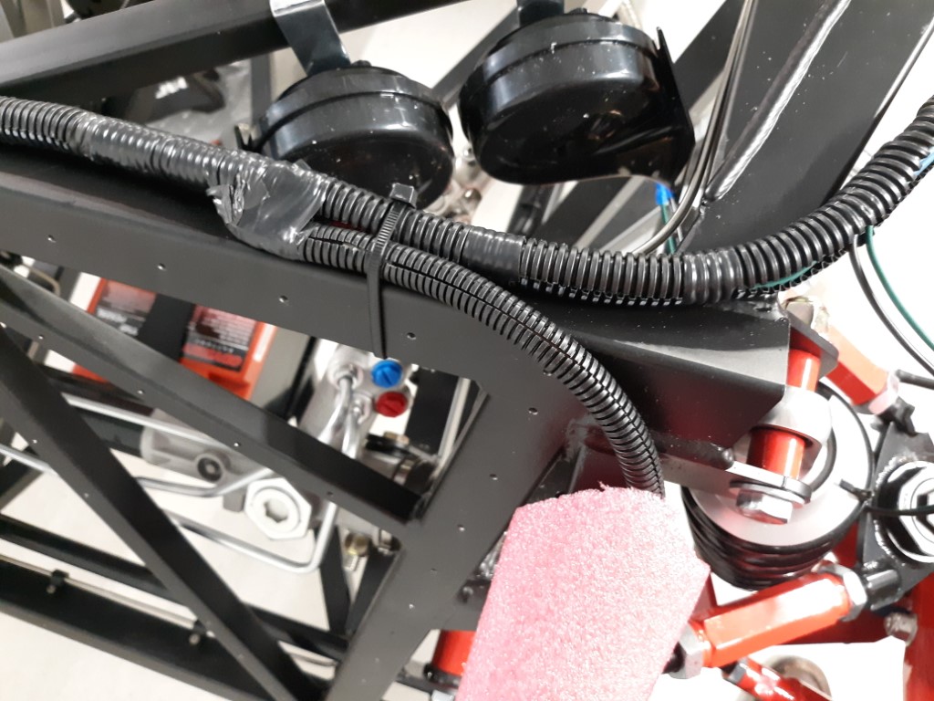
Steering rack question
The steering rack has two plugs. One blue and one red. Can anyone confirm, for me, that the red is the high pressure port from the pump and the blue is the low pressure port back to the reservoir. Thanks!
-
10-18-2022, 10:14 AM
#559
Senior Member


Originally Posted by
Namrups

Steering rack question
The steering rack has two plugs. One blue and one red. Can anyone confirm, for me, that the red is the high pressure port from the pump and the blue is the low pressure port back to the reservoir. Thanks!

The lower (smaller) connection is the inlet. Upper connection (larger) is the outlet.

Build 1: Mk3 Roadster #5125. Sold 11/08/2014.
Build 2: Mk4 Roadster #7750. Sold 04/10/2017.
Build Thread
Build 3: Mk4 Roadster 20th Anniversary #8674. Sold 09/07/2020.
Build Thread and
Video.
Build 4: Gen 3 Type 65 Coupe #59. Gen 3 Coyote. Legal 03/04/2020.
Build Thread and
Video
Build 5: 35 Hot Rod Truck #138. LS3 and 4L65E auto. Rcvd 01/05/2021. Legal 04/20/2023.
Build Thread. Sold 11/9/2023.
-
10-18-2022, 12:01 PM
#560

Originally Posted by
edwardb

The lower (smaller) connection is the inlet. Upper connection (larger) is the outlet.

Thanks Paul!


 Thanks:
  Likes:


 Reply With Quote


 ) Thanks for verifying. Do you know if there is any way to tap that signal and use it for the dash temperature gauge? There are two fan output wires. Maybe I can use fan output #2???


