-
11-09-2022, 04:21 PM
#601
Senior Member


Originally Posted by
Namrups

One for the electrical experts
The RF electrical installation manual shows cutting the relay wire for the fuel pump if using EFI.

I have not done this. As seen in my recent first start video the engine started and ran fine. Is cutting this wire a requirement and if I don't cut it what do I risk?
You only do that if you want to use the RF fuel pump circuit including the relay, inertia switch, and +12V wire back to the fuel pump. If you've already wired directly to the fuel pump from your Holly Sniper EFI system, technically not required to run your fuel pump. Only caution I'll cite is whether you have an inertia switch with your setup. It's a safety function that shuts down the fuel pump in the event of a hard collision or rollover. The RF fuel pump circuit wires that relay to ground through the inertia switch. If the switch opens, ground is broken, and the fuel pump circuit's power is cut off. Something to think about.
Build 1: Mk3 Roadster #5125. Sold 11/08/2014.
Build 2: Mk4 Roadster #7750. Sold 04/10/2017.
Build Thread
Build 3: Mk4 Roadster 20th Anniversary #8674. Sold 09/07/2020.
Build Thread and
Video.
Build 4: Gen 3 Type 65 Coupe #59. Gen 3 Coyote. Legal 03/04/2020.
Build Thread and
Video
Build 5: 35 Hot Rod Truck #138. LS3 and 4L65E auto. Rcvd 01/05/2021. Legal 04/20/2023.
Build Thread. Sold 11/9/2023.
-
11-09-2022, 04:40 PM
#602


Originally Posted by
edwardb

You only do that if you want to use the RF fuel pump circuit including the relay, inertia switch, and +12V wire back to the fuel pump. If you've already wired directly to the fuel pump from your Holly Sniper EFI system, technically not required to run your fuel pump. Only caution I'll cite is whether you have an inertia switch with your setup. It's a safety function that shuts down the fuel pump in the event of a hard collision or rollover. The RF fuel pump circuit wires that relay to ground through the inertia switch. If the switch opens, ground is broken, and the fuel pump circuit's power is cut off. Something to think about.
If I wanted to use the RF circuit with the inertia switch where would I connect the wire from the Sniper to? Right now I have cut the tan wire that ran from the fuse block to the fuel pump and attached the blue wire from the Sniper to the fuel pump. In order for the inertia switch to work should I cut the wire shown in the picture and reattach the tan wire from the fuse block to the Sniper blue/RF tan going to the pump? This has got me somewhat confused.
-
11-09-2022, 05:08 PM
#603
Senior Member


Originally Posted by
Namrups

If I wanted to use the RF circuit with the inertia switch where would I connect the wire from the Sniper to? Right now I have cut the tan wire that ran from the fuse block to the fuel pump and attached the blue wire from the Sniper to the fuel pump. In order for the inertia switch to work should I cut the wire shown in the picture and reattach the tan wire from the fuse block to the Sniper blue/RF tan going to the pump? This has got me somewhat confused.
If you (1) cut the shorter brown wire from the fuel pump fuse to the relay, (2) attached the Sniper blue wire to the brown wire from the relay (not the one from the fuse), and (3) used the RF fuel pump wire to the back of the car and plugged onto the in-tank fuel pump, the RF inertia switch is functional. It means the actual +12V to run the fuel pump is coming from your Sniper harness but routed through the RF wire to the back. With +12V on the red wire to the RF relay from the panel, and the relay ground going through the inertia switch, as long as the inertia switch is closed the relay will be energized (e.g. closed) and complete the circuit to the fuel pump. Easy enough to test. Shake or bump the inertia switch so that the button pops up. Your fuel pump shouldn't run with the key on until you push the button back down. Assuming it works properly, the inertia switch needs to be mounted where you can reasonably access it with the button up.
BTW, I'm a little breaking my own rules here. I haven't installed a Holley Sniper system. So giving this response only by looking at the Holly instructions. Seems straightforward, but no hands-on experience. The Sniper system is popular enough that hopefully others will chime in and either confirm or correct what I'm saying.
Build 1: Mk3 Roadster #5125. Sold 11/08/2014.
Build 2: Mk4 Roadster #7750. Sold 04/10/2017.
Build Thread
Build 3: Mk4 Roadster 20th Anniversary #8674. Sold 09/07/2020.
Build Thread and
Video.
Build 4: Gen 3 Type 65 Coupe #59. Gen 3 Coyote. Legal 03/04/2020.
Build Thread and
Video
Build 5: 35 Hot Rod Truck #138. LS3 and 4L65E auto. Rcvd 01/05/2021. Legal 04/20/2023.
Build Thread. Sold 11/9/2023.
-
11-09-2022, 06:12 PM
#604


Originally Posted by
edwardb

If you (1) cut the shorter brown wire from the fuel pump fuse to the relay, (2) attached the Sniper blue wire to the brown wire from the relay (not the one from the fuse), and (3) used the RF fuel pump wire to the back of the car and plugged onto the in-tank fuel pump, the RF inertia switch is functional. It means the actual +12V to run the fuel pump is coming from your Sniper harness but routed through the RF wire to the back. With +12V on the red wire to the RF relay from the panel, and the relay ground going through the inertia switch, as long as the inertia switch is closed the relay will be energized (e.g. closed) and complete the circuit to the fuel pump. Easy enough to test. Shake or bump the inertia switch so that the button pops up. Your fuel pump shouldn't run with the key on until you push the button back down. Assuming it works properly, the inertia switch needs to be mounted where you can reasonably access it with the button up.
BTW, I'm a little breaking my own rules here. I haven't installed a Holley Sniper system. So giving this response only by looking at the Holly instructions. Seems straightforward, but no hands-on experience. The Sniper system is popular enough that hopefully others will chime in and either confirm or correct what I'm saying.
This makes sense to me now. I was confusing myself as I was looking at the PDF version of the RF harness installation instructions that shows a different picture and trying to match that to the actual RF manual and the Sniper diagram. As always, Thank You Sir!
-
11-17-2022, 02:25 PM
#605
-
Post Thanks / Like - 0 Thanks, 1 Likes
-
11-18-2022, 10:17 PM
#606


Things don't always go as planned!
There have been numerous posts and threads about the challenges of building these cars. They are not "Leggo" kits. At times it takes creativity to find a solution to a problem. There is no more truth in that statement then when "things don't always go a planned".
It's no secret that I have modeled my build after Paul's (EdwardB's) coupe build. I have used a number of the same upgrades and custom parts that he used. One such item was the Corbeau Evolution X seats. One of the first items I ordered after ordering the coupe was the seats. I received them before the coupe and had them put away.
The plan was to mount them the identical way that Paul mounted his including the 1" high slider that he used so that I could eventually teach my daughter how to drive the car. She is shorter than I am and will need to move the seat closer to the pedals. Knowing I ordered the identical part numbers I didn't bother double checking anything earlier in the build. Why would I? It's the same stuff!
Well things don't always go as planned!!!
Getting ready to go-kart, in the near future, I decided to see if I could install the seats temporarily. I made up a pattern of the floor so that I could mark the locations for the mounting bolts. I attached a slider to one of the seats and worked it onto the car. Once in the car something just didn't seem right. I played around with it for a while and then decided to refresh my memory by looking back over Paul's installation.
What I found was my seats do not fit the coupe the same way they fit Paul's coupe. Corbeau has either redesigned the sliders or has switched suppliers. The new design raises the seat almost 1 3/4" above the floor. Paul's sliders are only 1". This puts the top of the seat 3/4" higher. Paul noted in his thread that the seat top rests against the rollbar. Given this extra height, mine really do. That area of the seat is highly padded and it should not effect anything other than rubbing if the seat is moved back or forth. The bigger issue is the fact that the seat itself does not fit between the seatbelt tabs. In Paul's build he mentioned that the seats fit between the tabs and he was able to slide the seat back towards the back panel. I can not do that. Either FF moved the location of the tabs or Corbeau widened the seat.
I still think I will be able to mount the seats with the sliders but it will be a tighter fit than I was expecting. I will post my solution as I figure it out.
My reason for this post was threefold.
First I wanted to point out that same part numbers may not mean the same parts. I have talked with Paul and verified we used the same part numbers.
Second was the fact that I made a first time builders mistake and took for granted that my parts were going to fit the same way as others posted. I should have verified my seats fit much earlier. I would have had other solutions such as moving the tabs.
Thirdly I wanted to point out that even the best plans sometimes go south. That is all part of these builds. It's our ability and the help of forum members and friends that can take something that is just not right and make "adjustments" to correct the issue and make it work.
Thanks to all of the forum members and my local friends that have helped my in my build!
-
Post Thanks / Like - 1 Thanks, 2 Likes
-
11-19-2022, 07:59 AM
#607
Member

Scott, thanks for the heads up. I have the same seats and sliders. I have not test fit them in the car yet.
I will see how they fit in mine this weekend, that is just about next on the to do list anyway.
Scott
Type 65 Daytona Coupe Complete Kit ordered 11/2021, delivered 7/25/2022....the fun has begun!
Build Thread
-
11-19-2022, 09:01 AM
#608

Originally Posted by
slarson

Scott, thanks for the heads up. I have the same seats and sliders. I have not test fit them in the car yet.
I will see how they fit in mine this weekend, that is just about next on the to do list anyway.
Scott
Let me know what you find!
-
11-19-2022, 10:11 PM
#609
Member

Scott, I didn't have a lot of time today. I'm having to replace a fence that Hurricane Nicole decided to knock down a few weeks ago (still not sure why she didn't like my fence).
The first thing I noticed on the slides is the two washers and the large cap screw that is holding the slides to the mount. So I removed the washers and replaced the cap screws with some pan head screws I had lying around. That got the slide height down to 1 5/16. My thought is to use a flat head screw that is countersunk into the base and that will get the height down to about 1 3/16"
I also flipped the slide release handle over so it's slightly angled up instead of down.
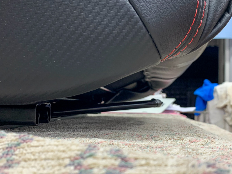
It seems like my seat is hitting the inside seat belt mount, the outside diagonal bar and the head rest hits the roll bar.
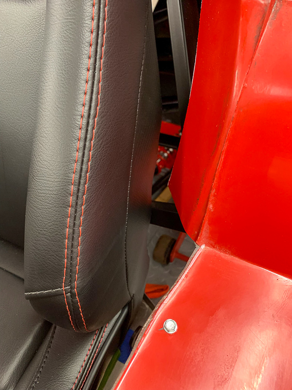
And the seat also seems to be angled to the outside.
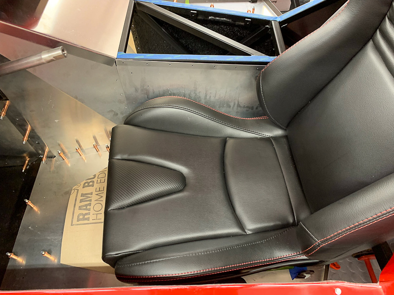
I don't like how the inner seat belt mount is behind the seat so the first thing I am going to try is to remove it. I will move it to the trans tunnel side of the aluminum panel.
Type 65 Daytona Coupe Complete Kit ordered 11/2021, delivered 7/25/2022....the fun has begun!
Build Thread
-
11-19-2022, 11:51 PM
#610


Originally Posted by
slarson

Scott, I didn't have a lot of time today. I'm having to replace a fence that Hurricane Nicole decided to knock down a few weeks ago (still not sure why she didn't like my fence).
The first thing I noticed on the slides is the two washers and the large cap screw that is holding the slides to the mount. So I removed the washers and replaced the cap screws with some pan head screws I had lying around. That got the slide height down to 1 5/16. My thought is to use a flat head screw that is countersunk into the base and that will get the height down to about 1 3/16"
I also flipped the slide release handle over so it's slightly angled up instead of down.

It seems like my seat is hitting the inside seat belt mount, the outside diagonal bar and the head rest hits the roll bar.

And the seat also seems to be angled to the outside.

I don't like how the inner seat belt mount is behind the seat so the first thing I am going to try is to remove it. I will move it to the trans tunnel side of the aluminum panel.
Keep me in the loop. I've already fastened my panels in here so moving the tabs is not going to happen.
-
11-20-2022, 01:32 AM
#611
Here's some photos of my Gen 3 Coupe and mounting of the same Corbeau seats that you're mounting.
I'll give due credit to Edwardb / Paul Borror who also mounted these Corbeau seats in his Gen 3 Coupe and provided many insights in his Coupe's build thread. Paul provided exceedingly helpful directly overhead photos of his seat mounts laying in their final place on the chassis. I used and verified those with my own seats and mounts and then took my own photos of the seat mounts in their final placement in my car. I created (and inserted below) a 4-photo collage of the seat mounts in the car both with the sheet metal laying in place and without the sheet metal. One key aspect is determining how/where to bolt the seat mount to the chassis. I've used 4 bolts with three mounted to the under-seat steel floor and a 4th thru one of the chassis frame tubes. The bolt heads face towards the ground and they feed up thru floating nutserts that are mounted in the seat mount. that 4th nut must be drilled and mounted yourself. the others are OK as is in the seat mount.
Luckily, I was able to mount the driver's seat fairly straight in the chassis, with all aspects clearing the structure of the car. The top outside corner of the driver's seat headrest does make slight contact with the closest roll cage tube, but I affixed a small piece of Velcro (the fuzzy piece) to the tube with the fuzzy side against the seat vinyl. That should prevent wear and any squeaking. Regarding the passenger seat, it had to deal with a slightly different cabin structure and had to be mounted at a slight angle, but that shouldn't be too objectionable. Of course, I had to determine the thread size and lengths of the SS button head mounting bolts to be used. I also used a few hardened steel washers between the floor and seat mount to account for any gaps.
Look very closely for positioning and alignments, as well as Edwardb's helpful photos inside the seat mounts;

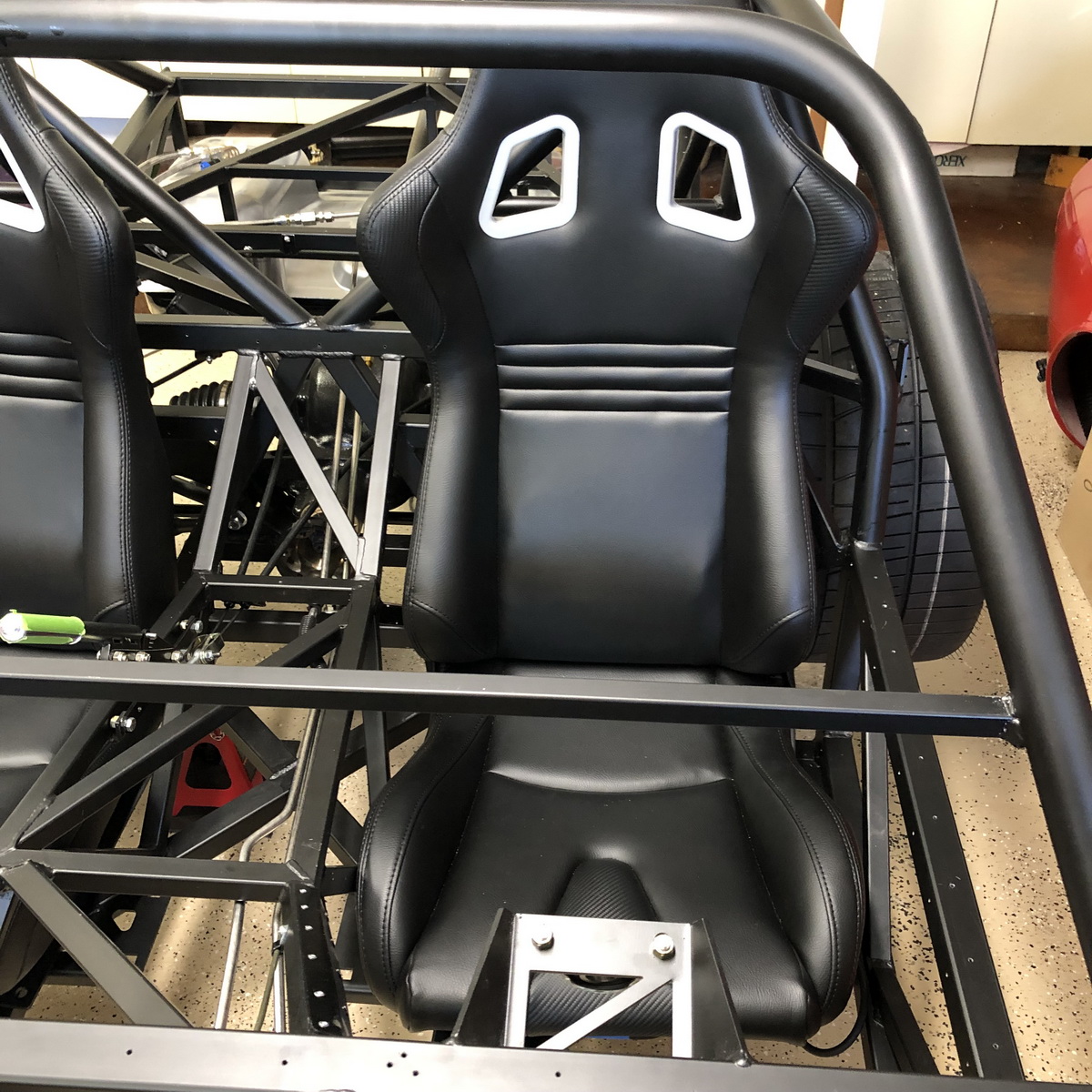
I believe that I did have to bend the outer seat belt attachment tab slightly outward to fully clear the seat.
My Coupe is at the painter right now, so I can't make any further checks or new photos.
I hope that helps.
Bob
-
Post Thanks / Like - 0 Thanks, 1 Likes
-
11-20-2022, 07:42 AM
#612
Senior Member


Originally Posted by
Bob Brandle

Here's some photos of my Gen 3 Coupe and mounting of the same Corbeau seats that you're mounting.
I'll give due credit to Edwardb / Paul Borror who also mounted these Corbeau seats in his Gen 3 Coupe and provided many insights in his Coupe's build thread. Paul provided exceedingly helpful directly overhead photos of his seat mounts laying in their final place on the chassis. I used and verified those with my own seats and mounts and then took my own photos of the seat mounts in their final placement in my car. I created (and inserted below) a 4-photo collage of the seat mounts in the car both with the sheet metal laying in place and without the sheet metal. One key aspect is determining how/where to bolt the seat mount to the chassis. I've used 4 bolts with three mounted to the under-seat steel floor and a 4th thru one of the chassis frame tubes. The bolt heads face towards the ground and they feed up thru floating nutserts that are mounted in the seat mount. that 4th nut must be drilled and mounted yourself. the others are OK as is in the seat mount.
Luckily, I was able to mount the driver's seat fairly straight in the chassis, with all aspects clearing the structure of the car. The top outside corner of the driver's seat headrest does make slight contact with the closest roll cage tube, but I affixed a small piece of Velcro (the fuzzy piece) to the tube with the fuzzy side against the seat vinyl. That should prevent wear and any squeaking. Regarding the passenger seat, it had to deal with a slightly different cabin structure and had to be mounted at a slight angle, but that shouldn't be too objectionable. Of course, I had to determine the thread size and lengths of the SS button head mounting bolts to be used. I also used a few hardened steel washers between the floor and seat mount to account for any gaps.
Look very closely for positioning and alignments, as well as Edwardb's helpful photos inside the seat mounts;
I believe that I did have to bend the outer seat belt attachment tab slightly outward to fully clear the seat.
My Coupe is at the painter right now, so I can't make any further checks or new photos.
I hope that helps.
Bob
Nice write-up Bob. And good job with the graphics. Clearly Corbeau significantly changed the slider brackets part number C22059 I purchased and installed in 2018. The same exact part number today has locks on both sliders (versus only one side before), a different handle, larger frame, and is slightly taller. I'm glad to see you could still make them work since several have chosen them based on my build thread.
I'm still not clear if the seats themselves have changed. I'd be surprised if they did since Corbeau markets them for the C5 and C6 Corvette. But anything's possible. Mine fit between the seat belt tabs with just enough room to attach the seat belts. Tight but workable. And yes they contact the roll bar cage (which I noted in my build thread) but hasn't been a problem for us. We rarely if ever slide the seats and with three seasons of driving haven't heard any sounds or shown any wear.
Last edited by edwardb; 11-20-2022 at 07:46 AM.
Build 1: Mk3 Roadster #5125. Sold 11/08/2014.
Build 2: Mk4 Roadster #7750. Sold 04/10/2017.
Build Thread
Build 3: Mk4 Roadster 20th Anniversary #8674. Sold 09/07/2020.
Build Thread and
Video.
Build 4: Gen 3 Type 65 Coupe #59. Gen 3 Coyote. Legal 03/04/2020.
Build Thread and
Video
Build 5: 35 Hot Rod Truck #138. LS3 and 4L65E auto. Rcvd 01/05/2021. Legal 04/20/2023.
Build Thread. Sold 11/9/2023.
-
11-20-2022, 07:52 AM
#613


Originally Posted by
Bob Brandle

Here's some photos of my Gen 3 Coupe and mounting of the same Corbeau seats that you're mounting.
I'll give due credit to Edwardb / Paul Borror who also mounted these Corbeau seats in his Gen 3 Coupe and provided many insights in his Coupe's build thread. Paul provided exceedingly helpful directly overhead photos of his seat mounts laying in their final place on the chassis. I used and verified those with my own seats and mounts and then took my own photos of the seat mounts in their final placement in my car. I created (and inserted below) a 4-photo collage of the seat mounts in the car both with the sheet metal laying in place and without the sheet metal. One key aspect is determining how/where to bolt the seat mount to the chassis. I've used 4 bolts with three mounted to the under-seat steel floor and a 4th thru one of the chassis frame tubes. The bolt heads face towards the ground and they feed up thru floating nutserts that are mounted in the seat mount. that 4th nut must be drilled and mounted yourself. the others are OK as is in the seat mount.
Luckily, I was able to mount the driver's seat fairly straight in the chassis, with all aspects clearing the structure of the car. The top outside corner of the driver's seat headrest does make slight contact with the closest roll cage tube, but I affixed a small piece of Velcro (the fuzzy piece) to the tube with the fuzzy side against the seat vinyl. That should prevent wear and any squeaking. Regarding the passenger seat, it had to deal with a slightly different cabin structure and had to be mounted at a slight angle, but that shouldn't be too objectionable. Of course, I had to determine the thread size and lengths of the SS button head mounting bolts to be used. I also used a few hardened steel washers between the floor and seat mount to account for any gaps.
Look very closely for positioning and alignments, as well as Edwardb's helpful photos inside the seat mounts;


I believe that I did have to bend the outer seat belt attachment tab slightly outward to fully clear the seat.
My Coupe is at the painter right now, so I can't make any further checks or new photos.
I hope that helps.
Bob
X2 Great write up! Between Paul's excellent thread and your pics I am sure I can get these mounted. My only concern right now is the seat width and how far back I can position it. In the end I don't feel it will be a major issue because I'm only 5'-8".
-
11-22-2022, 02:13 PM
#614
-
11-22-2022, 02:25 PM
#615
-
11-22-2022, 03:17 PM
#616
Referencing the TKX shifter placement issue a few pages back in your build thread, I'm also building a SBF Gen 3 Coupe, and was thinking of going with a TKX, but I'm not excited about cutting that crossmember if I dont' have to. Would the White Lighting shifter from American Powertrain have solved the issue? https://youtu.be/TiMYBghXnC0 It certainly looks like it would fix the shift lever placement with a 3" extension, but I'm wondering if there is enough vertical clearance between the shift mount pad and the bottom of the crossmember you had to cut for it to work? Just curious what your thoughts are for this as possible solution. Otherwise I might stick with a T-56.
-
11-22-2022, 04:31 PM
#617
Not sure there will be room. It still looks too high and will hit the crossmember.
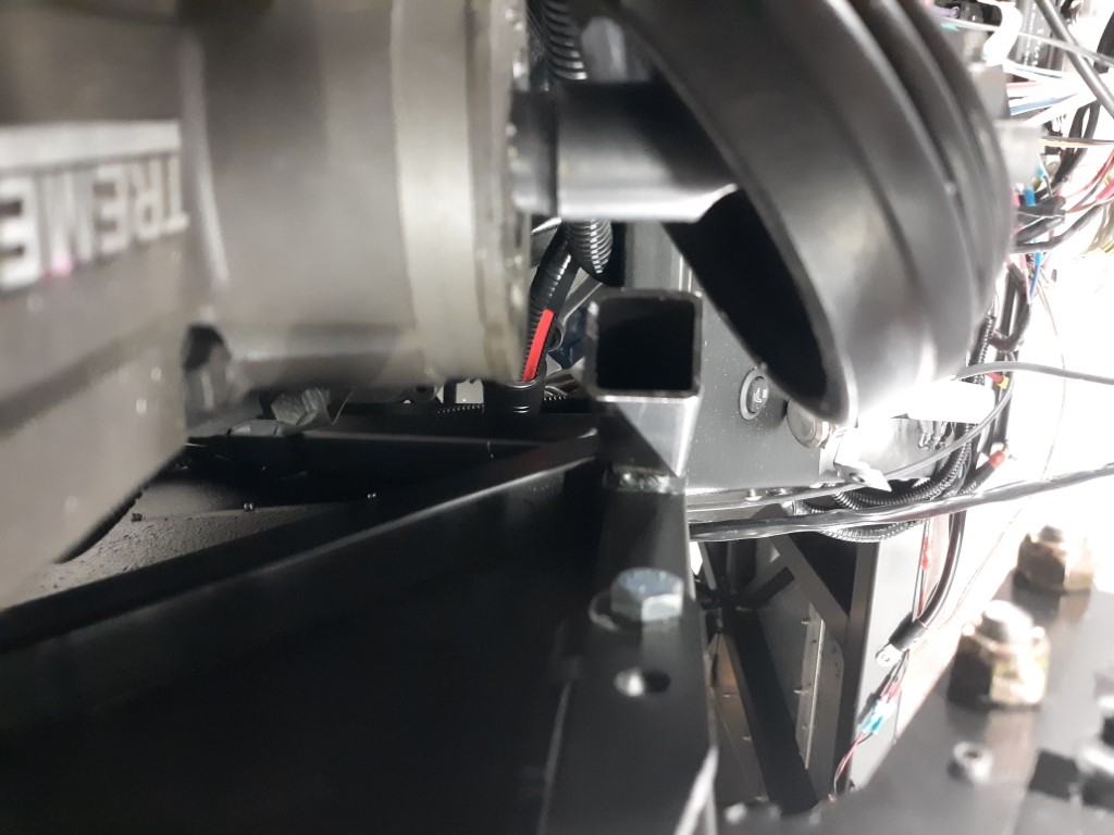
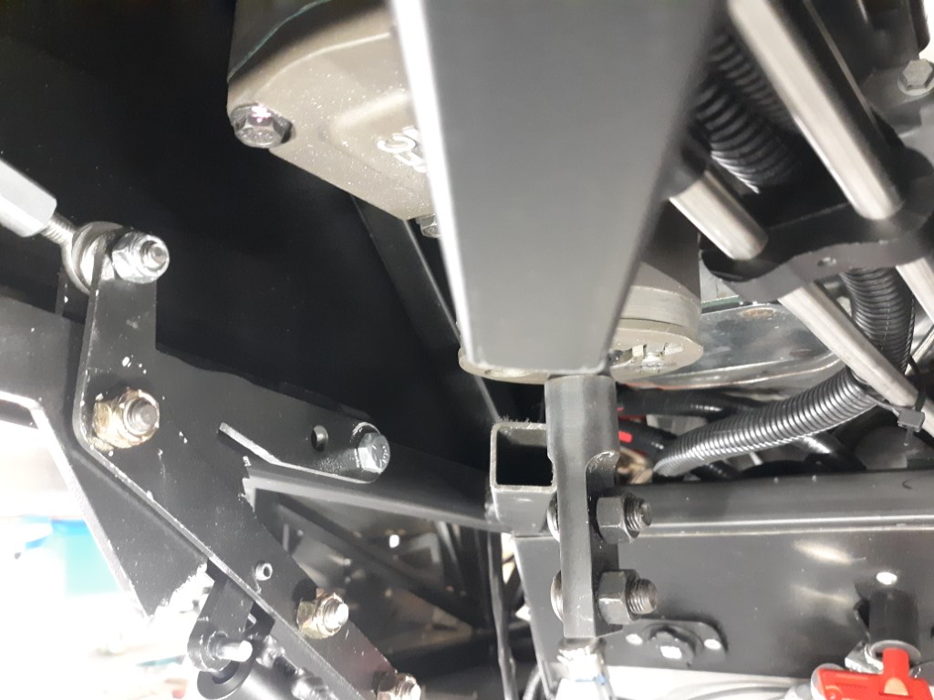
The only way I can see would be to use the forward "midshift" kit but it might be too close to the dash then.
-
11-22-2022, 05:13 PM
#618

Originally Posted by
DesertSn8ke

Referencing the TKX shifter placement issue a few pages back in your build thread, I'm also building a SBF Gen 3 Coupe, and was thinking of going with a TKX, but I'm not excited about cutting that crossmember if I dont' have to. Would the White Lighting shifter from American Powertrain have solved the issue?
https://youtu.be/TiMYBghXnC0 It certainly looks like it would fix the shift lever placement with a 3" extension, but I'm wondering if there is enough vertical clearance between the shift mount pad and the bottom of the crossmember you had to cut for it to work? Just curious what your thoughts are for this as possible solution. Otherwise I might stick with a T-56.
I am also building a SBF Gen3 Coupe. I used a front shift kit from Silver Sport Transmissions. It clears everything, no cutting required, and with a straight 6" shift lever, position is good. I will get a picture up on my build thread in the next could days.
-
11-22-2022, 05:46 PM
#619
Too late for me but I am interested in your pics. Might be an upgrade in the future and I'm sure others are interested!
-
11-22-2022, 06:09 PM
#620

Originally Posted by
GT_Rich

I am also building a SBF Gen3 Coupe. I used a front shift kit from Silver Sport Transmissions. It clears everything, no cutting required, and with a straight 6" shift lever, position is good. I will get a picture up on my build thread in the next could days.
It is a pricey option, but I am going with it as well. Would love to see some pictures of where the shifter handle is located in the car.
Namrups, just a thought. Looking at how close the seat(s) are to the bare floor. Are you going to have room to add insulation and/or carpeting? Assuming you are going to do that.
My Type 65 Coupe: Ordered May 27, 2021. Arrived November 19, 2021.
I would like to treat my gas pedal as a binary operator. It would be nice to get the cooperation of everyone in front of me. 
-
11-22-2022, 06:38 PM
#621

Originally Posted by
Skuzzy

It is a pricey option, but I am going with it as well. Would love to see some pictures of where the shifter handle is located in the car.
Namrups, just a thought. Looking at how close the seat(s) are to the bare floor. Are you going to have room to add insulation and/or carpeting? Assuming you are going to do that.
Very good question. I don't see room to use any type of heat and sound "mat" and carpet. Using the spray on heat and sound material (same as EdwardB's) and carpet should work. It will be tight.
-
11-23-2022, 11:45 PM
#622
Good info on possible shifter solutions. Curious to see pictures of the Silver Sport option. I'm very early in the build yet. Finished inventory, marking and pulling panels off. Haven't ordered an engine and trans yet so I have options. Just waiting on some quotes to come in.
-
11-24-2022, 09:20 AM
#623

Originally Posted by
DesertSn8ke

Good info on possible shifter solutions. Curious to see pictures of the Silver Sport option. I'm very early in the build yet. Finished inventory, marking and pulling panels off. Haven't ordered an engine and trans yet so I have options. Just waiting on some quotes to come in.
GT_Rich has recently posted a video of his build with that shift kit. (427 SBF Coupe R Build) That looks like the way to go if you don't want to cut the cross brace.
-
11-26-2022, 03:07 PM
#624
-
11-26-2022, 08:27 PM
#625
Senior Member

Looks great Scott! You did not waste any time! I can see into my future with the seating issue you had as am going the same way and noticed my seat mounts look different than Paul's as well, so will be tackling the very same issue you brought up, appreciate everyone's input there, will be adding my own once I get to that point  . Can't wait to see what you do with the rest of the cockpit, I assume carpet? FYI those tires look bad *** to me....must be the zig-zags...
-
11-26-2022, 08:56 PM
#626


I made the rookie mistake of not double checking. If I had, I might have been able to do something different. Moving the seat harness tabs out wider is the first thing that comes to mind. It might let the seats sit farther back. By the time I realized something was different I had already had all the panels installed. Not going to pull them back out. I'm only 5'-8" so even though the seats are closer to the wheel it is ok for me. With the sliders it will move it close enough for my daughter also. I did trim the RT directional mount as much as I could to move the wheel as close to the dash as possible.
My plan is to use the Lizard Skin products covered by carpet. In the footbox areas I have used Duraliner and Dynaliner. I'm thinking about using felt on the roof instead of the FF liner.
If I had it to do over again I might use 1/16" foam on the dash instead of the 1/8". I'm not sure I really like the way the switches and mounting screws bury themselves in the foam the way they do. At this point I'm just snugging them up enough to hold in place. Not tightening them down completely. I had thought about just using two layers of vinyl but I was afraid that any imperfection might show thru. The foam hides them.
The tires are Falken RT615's. The Falken RT660's were highly recommended but IMO they are more of a track tire with less tread. I believe the 615's are more of a street tire and they were a little less expensive.
-
Post Thanks / Like - 0 Thanks, 1 Likes
-
11-28-2022, 10:17 AM
#627
Senior Member

Dash looks fantastic Scott. It was my favorite part of the build. Starting to look like a real boy.
-
11-28-2022, 12:13 PM
#628

Originally Posted by
Blitzboy54

Dash looks fantastic Scott. It was my favorite part of the build. Starting to look like a real boy.
Thanks Jesse!
-
11-30-2022, 09:21 AM
#629
East Coast Speed Machines

FFR 1879, Blown DSS 306,REDLINE management, VeryCoolParts Tuned 460RWHP
FFR 818S, The Flash, Chassis #5, 2.0L, LSD, Electromotive TEC-S, VCP Tuned, 278RWHP 265 RWTQ
FFR 6651, Green Lantern, 408W Crate, Hellion 66mm Turbo, JGS Waste gate / Blowoff valve, Tec-GT management, VCP Tuned, 575 RWHP, 690 RWTQ
FFR 8335, Black Mamba, 289 FIA CSX 2001 tribute car, 347, 48 IDA webers, VCP Tuned, 311 RWHP 386 RWTQ, 3-link, Trigo's
FFR 0004, Gen 3 , Hawk Coupe, Coyote twin turbo, 683 RWHP 559 RWTQ, IRS, VCP Tuned. "not too shabby"
US ARMY Maintenance Test Pilot (CW4 Retired)
-
11-30-2022, 09:39 AM
#630

Originally Posted by
Erik W. Treves

Looking really good~!
Thanks Eric!
-
11-30-2022, 10:45 AM
#631
Not a waxer

-
11-30-2022, 09:13 PM
#632

Originally Posted by
Jeff Kleiner

I agree with Erik!
Jeff
Thanks Jeff! Appreciate the support!
-
11-30-2022, 09:27 PM
#633
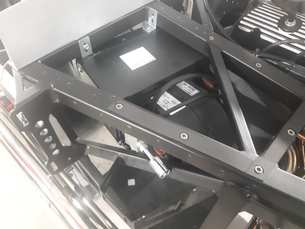
While waiting for my throttle linkage to arrive I started on the AC/Heat.
Located and mounted the AC/Heater unit. If you look close you can see that I had to heat and bend the drain connection. No matter what I did I couldn't get the unit to clear both that drain and the AC fitting against the frame. The drain was plastic and with the heat gun was the easiest solution.
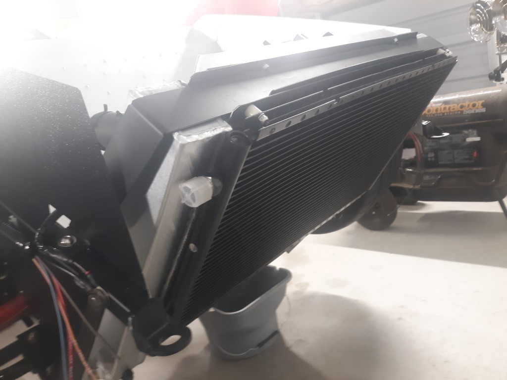
Also mounted the condenser. This is not the kit supplied condenser. Following Paul's lead I went with the Vintage Air A/C Condenser part# VTA-03263-VUC from Summit Racing. A little pricy but it fits the radiator better. I used the kit supplied mounting hardware without issue.
-
Post Thanks / Like - 0 Thanks, 1 Likes
-
12-01-2022, 02:22 AM
#634
Senior Member

Thank you for documenting your progress and providing insight into your build. I'm in the planning phase and this has been very helpful. Your car looks great! - Jim
-
Post Thanks / Like - 1 Thanks, 0 Likes
-
12-10-2022, 10:24 PM
#635
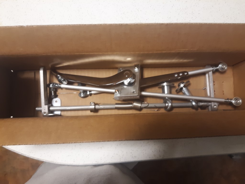
Received my throttle linkage from Forte today. Hopefully I can get it installed and maybe have my go-kart by next weekend if the weather holds!
-
Post Thanks / Like - 0 Thanks, 1 Likes
-
12-12-2022, 04:07 PM
#636
-
12-12-2022, 04:16 PM
#637
-
12-12-2022, 04:36 PM
#638
-
Post Thanks / Like - 0 Thanks, 1 Likes
-
12-12-2022, 07:14 PM
#639
I have to ask, what is the point of all that over just using the cable and pedal FFR supplies?
-
12-12-2022, 08:44 PM
#640

Originally Posted by
GT_Rich

I have to ask, what is the point of all that over just using the cable and pedal FFR supplies?
Rear the following link: https://thefactoryfiveforum.com/show...anical-linkage


 Thanks:
  Likes:


 Reply With Quote


 . Can't wait to see what you do with the rest of the cockpit, I assume carpet? FYI those tires look bad *** to me....must be the zig-zags...


