-
Senior Member

I've lowered the engine./trans about as low as I dare. Lowering it this much causes a slight upward angle on the drive axles. Not ideal, but in the acceptable range I think. Pushing the engine/trans back as far as I have also requires me to relocate one of the rear wish bone links that rubs the CV joint boot.
IMG_20230219_095926724.jpg IMG_20230219_100522838.jpg IMG_20230103_113230945.jpg
-
Senior Member
Motor Mounts Started
I got started on the motor mounts and really like the way they are coming together. I designed the mounts in CAD and had them made out of 3/16" plate steel. I used SendCutSend again and they did a great job. I could have made the brackets myself but I didn't have the right material on hand and for the cost it didn't seem worth my time. The laser cut brackets fit perfectly.
Here are the brackets as they came from SendCutSend, followed by versions after some needed welding. And finally painted, from this angle you can see that the intake side needed two different length standoffs as no two bolt holes on that side of the block, in the area I wanted my motor mounts, are on the same plane. ")
IMG_20230301_145258797.jpg IMG_20230301_153343812.jpg IMG_20230302_095950203.jpg
Next I had to secure the engine/trans in space so I could get real measurement between the frame and the motor mounts. I used multiple straps pulling against one another in all three planes of movement. This allowed me to adjust the precise position of things to get the engine centered in the engine bay, the angle of tilt (approx 15 degrees), and transmission angle relative to the ground set right.
IMG_20230302_145613187.jpg IMG_20230302_145621558.jpg IMG_20230302_145632607.jpg IMG_20230302_145424461.jpg IMG_20230302_145548424.jpg
Everything is only tacked in place for now. After I get the transmission mounts and frame bracing in place I will final weld all the pieces.
-
Post Thanks / Like - 1 Thanks, 1 Likes
 Rob T
Rob T thanked for this post
-
Senior Member
Custom Throttle Body Adapter
I finished the custom throttle body adapter that was needed to join the larger throttle body from my Subaru EZ36 motor to the Honda intake manifold.
In the first picture you can see the 4 countersunk holes that fasten the adapter to the intake manifold and the 4 tapped holes that the throttle body bolts too. In the second picture you can see the taper that transitions smoothly from the smaller inner diameter of the throttle body to the larger inner diameter of the intake manifold.
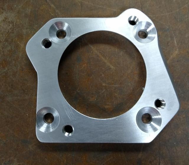

This small piece was complex enough that I needed to design it in CAD first to be sure everything would come together correctly. I'm embarrassed to say I made MANY prototypes before I got everything to fit up right. I started off using a 3D printer but found that the tolerances were too loose so I moved on to making them out of MDF board on my milling machine.
Here are some of the prototypes and test pieces.
IMG_20230305_165043894.jpg
Here are some more pics of the setup in the lathe cutting that smooth taper. It was such an odd shaped part I had to bolt it to a square board to mount it up in my 4 jaw chuck. Finally some close ups of the finished part.
IMG_20230305_164950862.jpg IMG_20230305_172013255.jpg IMG_20230305_171724814.jpg IMG_20230305_172002529.jpg IMG_20230305_171718525.jpg IMG_20230305_171822548.jpg IMG_20230305_171840281.jpg
Last edited by Hobby Racer; 03-05-2023 at 06:06 PM.
-
Post Thanks / Like - 0 Thanks, 1 Likes
-
Thinker of thoughts

Very nice work. Sometimes I find that when I skip the prototyping stage (because in my head it is going to come out perfect without doing that) I end up scrapping the part and starting again....and again....and again. I learn slowly.
Rick
-
Senior Member

Very Nice. One advantage of bolting the odd shaped piece to the board in the 4-jaw was that you could cut the taper just past the end of the piece into the wood without hitting the 4 jaw. Genius.
-
Senior Member
Motor & Transmission Mounts Finished!
I had a marathon day of welding. I finish welded the motor mounts, made the transmission mounts, made a small cross brace and finally welded everything into place! I might add some cross bracing if I can find a spot that it will fit.
IMG_20230307_162123094.jpg IMG_20230307_162143736.jpg IMG_20230307_162133243.jpg IMG_20230307_162159328.jpg IMG_20230307_162128373.jpg
-
Post Thanks / Like - 0 Thanks, 3 Likes
-
Senior Member
Last edited by Hobby Racer; 03-07-2023 at 05:36 PM.
-
Post Thanks / Like - 0 Thanks, 4 Likes
-
Senior Member

I really hope that you’re rewarded for your hard work in your quest for speed and reliability.
Jet
-
Post Thanks / Like - 1 Thanks, 0 Likes
-
Senior Member
-
Post Thanks / Like - 1 Thanks, 0 Likes
Rob T thanked for this post
-
Senior Member
-
Post Thanks / Like - 0 Thanks, 1 Likes
-
Is that 6 spd transmission the same width as the 5 spd? Im just wondering if it will affect the length that the CV axle needs to be? After all the issues I'm having trying to find a replacement CV joint for my 818 I am very tuned into this issue!
-
Senior Member

Originally Posted by
Mark Eaton

Is that 6 spd transmission the same width as the 5 spd? Im just wondering if it will affect the length that the CV axle needs to be? After all the issues I'm having trying to find a replacement CV joint for my 818 I am very tuned into this issue!
The 6 speed is wider, taller, longer and heavier than the 5 speed. It does not effect the axles though. The FFR design has plenty of room for lateral movement and slight variations in transmission width and placement. I used the FFR axles in both my original 5 speed and this 6 speed.
-
Senior Member
After some well spent time with the die grinder, the intake manifold is now port matched to the cylinder head. It really makes the cheap knock off manifold very nice.

Last edited by Hobby Racer; 03-15-2023 at 05:16 PM.
-
Post Thanks / Like - 0 Thanks, 1 Likes
-
Senior Member
I know it looks like I'm going backwards, but it really is forward progress. 
In order to run a baffled wet sump oil pan you have to change the oil pump from the stock K24 to the stock K20 version. Those do not have balance shafts that get in the way of the pan baffles. Plus they are lighter, allow the engine to rev higher and provide a more stable oil supply. But to do it you need to remove the front timing chain and all the bits associated with it.

-
Post Thanks / Like - 0 Thanks, 1 Likes
-
Senior Member

Watching your progress with interest. On the one hand, you're making it look easy. On the other hand, I've given up any fantasy of doing it myself.
-
Post Thanks / Like - 1 Thanks, 0 Likes
-
Senior Member
Power-train goes back in for final fitments tomorrow!
Now tell me that red valve cover isn't worth at least 15hp!  It does look a lot nicer now.

IMG_20230323_170358679.jpgIMG_20230323_170353921.jpgIMG_20230323_170350460.jpg
-
Does look sharp! Love following your buildup.
-
Post Thanks / Like - 1 Thanks, 0 Likes
-
Senior Member
Almost Done!
Finishing up, connecting oil, cooling, exhaust, wiring etc... Fabricated the new rear tower bracing. Because the motor is right up against the rear firewall and slanted 15 degrees the supports are asymmetrical and do not meet in the center of the firewall.
I'm very pleased with how the packaging is falling into place.
Hoping for first start in April.
IMG_20230329_180007327.jpg IMG_20230329_175948063.jpg IMG_20230329_175939199.jpg
-
Post Thanks / Like - 0 Thanks, 3 Likes
-
Senior Member
I'm looking at the transmission cable routing and I am having a difficult time finding a good way to do it. With the engine tight against the firewall it limits my options. I'm even considering running them under the car starting at the gas tank and coming up under the transmission.
Any ideas are welcome!
-
Do something similar to Art and put mechanical linkage in the cockpit that moves the cables to the far edge of the cabin and then route your cables back along the fender well.
-
Senior Member
Originally Posted by
Ajzride
Do something similar to Art and put mechanical linkage in the cockpit that moves the cables to the far edge of the cabin and then route your cables back along the fender well.
I thought about that for a bit, but with the stock fuel tank there is not enough room to run the rods and linkages. I would need to swap to a different tank like Art did, and if I do that I could just customize the tank to run the cable under it.
Wait a minute, maybe I'll look at putting a pass through port in the tank.
-
I raise my tank 1" and went under it.
-
Senior Member
Originally Posted by
Ajzride
I raise my tank 1" and went under it.
Ok, I like that idea. What did you use under the tank to raise it up?
Last edited by Hobby Racer; 03-31-2023 at 05:12 PM.
-
Originally Posted by
Hobby Racer
Ok, I like that idea. What did you use under the tank to raise it up?
1" square tube, just like the frame.
-
Post Thanks / Like - 1 Thanks, 0 Likes
-
Senior Member
Originally Posted by
Ajzride
1" square tube, just like the frame.
Any pics?
-
Not great ones. You can kind of see where I boxed the frame so I could go through it here:
https://thefactoryfiveforum.com/show...l=1#post388714
I'll try to get some more tomorrow out in the garage.
-
Senior Member
Originally Posted by
Ajzride
No need, I get the idea from the post. I'm going to mock up something this weekend and see how I like it. Thanks!
-
-
Senior Member
I see your also using a different tank. I'm still using the FFR steel tank and I don't think you can raise it much before it contacts the aluminum removable firewall panel.
I think I'm just going to bore a hole through the tank in the location I need and weld in a tube. This will give me a nice pass thru to run the cables and reverse lockout cable.
-
Originally Posted by
Hobby Racer
I see your also using a different tank. I'm still using the FFR steel tank and I don't think you can raise it much before it contacts the aluminum removable firewall panel.
I think I'm just going to bore a hole through the tank in the location I need and weld in a tube. This will give me a nice pass thru to run the cables and reverse lockout cable.
I put a tunnel through my gas tank this winter for shift rods and it worked out pretty well....do wish my welding skills were better, but it got there in the end. It makes for a nice direct path to the back of the car! I put a pivot point in just behind the firewall, then transitioned to short 3ft cables under the engine. It seems to shift well, but I haven't actually gotten the car back on the road yet to test.
tank tunnel.jpg
pivot.jpg
-
Post Thanks / Like - 1 Thanks, 1 Likes
-
Senior Member
Fuel Tank Pass Through Cut

I cut the pass thru holes today. The compound angles needed to get the 2" pipe to pass through cleanly started to make my head hurt so I modeled it up in CAD and just asked the computer for the angles. 
Tomorrow, hopefully I will have time to cut the tube ends flush with the tank and weld it all up.
IMG_20230402_191945420.jpg IMG_20230402_191924225.jpg IMG_20230402_181912203.jpg IMG_20230402_184633385.jpg IMG_20230402_184644663.jpg
Last edited by Hobby Racer; 04-02-2023 at 07:20 PM.
-
Post Thanks / Like - 0 Thanks, 2 Likes
-
A fuel tank strapped to a milling machine makes me feel inadequate.
-
Post Thanks / Like - 0 Thanks, 1 Likes
-
Senior Member
Two things...1) I guess you got all of the explosive vapor out of the fuel tank (I'm glad) 2) The answer to the question is "because I can". I am constantly amazed by your ingenuity and resourcefulness when it comes to solving complex problems with precision. It is inspiring.
-
Post Thanks / Like - 1 Thanks, 2 Likes
-
Senior Member
Transmission Cable Routing Complete
I finished welding the pass through tube in the fuel tank. The routing came out very good. I fabricated a new mounting point at the rear for securing the cables. Now the engine and transmission can be removed from the car without disturbing the cables.
IMG_20230406_094129518.jpg IMG_20230406_094139585.jpg IMG_20230406_094114127.jpg IMG_20230406_094107451.jpg IMG_20230406_094059609.jpg
-
Post Thanks / Like - 0 Thanks, 1 Likes
-
Senior Member
-
Post Thanks / Like - 0 Thanks, 2 Likes
-
Which ECU are you running? First post just said "existing standalone".
-
Senior Member
Originally Posted by
Ajzride
Which ECU are you running? First post just said "existing standalone".
I'm running a MegaSquirt MS3Pro ECU.
-
Looking great. Can't wait to hear it run and see how it performs versus the subie engine.
-
"Good Judgement comes from Experience. Experience comes from Bad Judgement"
Owner: Colonel Red Racing
eBAy Store:
http://stores.ebay.com/colonelredracing
818R ICSCC SPM
Palatov DP4 - ICSCC Sports Racer
-
Senior Member

Great work, I'm glad to see you make all the progress you have even with the earlier EJ setbacks
Gen 3 Type 65 Coupe builder


 Thanks:
  Likes:


 Reply With Quote


