-
Senior Member

-
Senior Member
-
Post Thanks / Like - 0 Thanks, 1 Likes
-
Senior Member
-
Senior Member
-
Senior Member
-
Senior Member
One Way gas valve, Fuel filter and Main 12v battery cutoff switch
Short update. Yesterday I was completing my Oil, Gas and Brake Lines. A little boring and not picture worthy. I did mount a large Holly 10 micron gas filter. Attached to the gas filter housing is a one way valve for fuel flow. The one way valve came with my gas line kit.... so I stuck it in. I used a couple 1.5" SS T-Hose clamps for the filter.

I'm also installing, by the battery somewhere, this Painless battery switch/solenoid. It will be activated by a "momentary" button switch in the cab.... i.e, one depression will cause a disconnect and the next depression causes a connect. I'll hide this button switch under the dash... kind of a "security" device. Off the "hot side" of the switch, I'll run constant 12v power for devices that always needs power, e.g., radio, clock, etc.

Today, I'll be mount the fuel regulator, radiator overflow, windshield washer canister/pump, horn, etc.
Thx Mark
-
Post Thanks / Like - 0 Thanks, 1 Likes
-
Senior Member
Radiator Overflow, Windshield Washer & Furl Pressure Regulator Installed
Light day yesterday... Quick update.
I installed the Radiator overflow in the only place it would fit, then the Windshield washer canister and pump combo unit followed by the Aeromotive fuel pressure regulator. With the Coyote engine, there isn't all that much room!!! So it's a bit crowded to get it all to fit. I had to make a bracket to mount the windshield washer unit to it that will raised it off the firewall about 1" to allow for the fuel lines and AN fittings to the fuel pressure regulator to run behind it. Coming off the fuel pressure regulator is an AN fitting with a 1/8"npt tap in it to allow me to install my fuel pressure regulator sensor for my fuel pressure gauge. Then, off this AN fitting will be another smaller 10 micron fuel filter. From there, I'll have to make my last short fuel line. I ordered a 3/8" quick disconnect to 6AN male fitting that will connect the the Coyote's fuel rail. I'll have that later in the week.

Here's a better shot to show the radiator overflow tank install

On a Side Note: I received my replacement bushing sleeves for the rear lower control arms. The originals were 12mm ID and should have been 14mm ID. I understand recent deliveries of other's kits have had this same issue. So, I removed the 12mm ones only to find out the 14mm replacements are ~1/8" too long. I didn't feel like it yesterday to deal with it.... so that's one of my first tasks this morning.
Also, I'm expecting a FedEx delivery today with most of my MIK/POL backorder items in it. Fingers Crossed!
-
Senior Member
Help Needed with Front Radiator Assembly Build
OK.... Need some help here.
I started the build of the front radiator assembly.... problem is, the manuals, i.e., both the '35 Truck manual and the FF A/C Install manual does not match at all the current product/parts that FF has designed, manufactured and shipped. So, here's my confusion.
In the pic below, you see I've attached the mounting tabs to the A/C condenser and setting in the grill. All good here.

In the next 2 pics, you see the tabs on the actual radiator have a pretty tall gap.... ~3/4". The 2 hood brackets that goes on the top tabs are 3/16" and the spacers FF supplied are 7/16".... so all good for the top bracket/tab install.
My question is, how do I fill the gap on the bottom tabs? All my spacers are all the same 7/16".... so, not sure how I fill with gap as I don't see anything else to install on the lower/bottom tabs in the manuals. Sure, I can add my own spacers.... but I think I'm missing something here!!!
Any input here most welcome..... HELP.


Once I get this solved, I'm also going to build a fan shroud so the exposed radiator above and below the fan is covered, thereby forcing all the air flow through the radiator when the fan is on vs the fan pulling warm air from the surrounding open area around the fan's diameter. I assume that's been done before by some.... so any input, pictures, or drawings would help me not reinvent the wheel.
Thx Mark
Last edited by mkassab; 05-16-2023 at 06:57 AM.
-
Senior Member

I purchased one from Replicaparts made for the 33 Hot Rod and modified it slightly to fit the truck. Please see post 466 on my build page.
Cheers!
Once again with an 88 mm Turbo, Big Block Chevy powered, 35 Hot Rod Pickup
-
Senior Member

Originally Posted by
Pat Landymore

I purchased one from Replicaparts made for the 33 Hot Rod and modified it slightly to fit the truck. Please see post 466 on my build page.
Cheers!
Thanks Pat... I just contacted Mike at Replicaparts for my radiator shroud. I may mount mine differently than you did.
Mark
-
Senior Member
Radiator and Hood Hinge Bracket mess?
OK, So far, here's where I'm at. Per the manual, for the truck specifically, the Hood Hinge Bracket clearly sets on top of the condenser/grill top tab (and oriented as shown with the 90* bend facing outward), followed by the 7/16" spacer and then the radiator tab and screwed down..... and it looks like the next two pictures.
This shot is view looking up along the grill/rad and the hood hinge bracket mounted where the manual says to.

This next shot is a top down view of the same assembly as the above pic

However, others, like Don, say the hood hinge bracket should be reversed left and right (i.e., 90* bend facing inward) and the bracket on top of the radiator tab? My concern here is if I move the bracket up (i.e., closer out towards the firewall) the Hood itself would also be pushed toward the firewall/rear of the truck.... Unless, the bracket move out can be adjusted for in another set??
ANY Comments here would really help me.
On page 408 of the truck manual, the pic below is shown and this is exactly how I have setup now.

One last pic showing the bottom tabs where I used the 7/16" spacer and washers to make up the thickness of the bracket. However, If I do end up NOT following the manual and placing the hood hinge bracket on top of the radiator tab, then the washers on the lower tab may not be needed (as I'd still need more than the 7/16" spacers to fill the ~3/4" gap/space between the rad tab and the condenser/grill tab.
Until I can receive concrete info, I'm going to leave my setup as is for now..... as it matches and follows all 3 manuals (Truck manual for a truck radiator and hood hinge bracket setup, the Coyote Engine Manual for the truck and the Coyote A/C manual). As I proceed with the build, in particular the hood and hinge, I'll adj there if needed.
Thx Mark
Last edited by mkassab; 05-17-2023 at 01:57 PM.
-
Senior Member
-
Senior Member
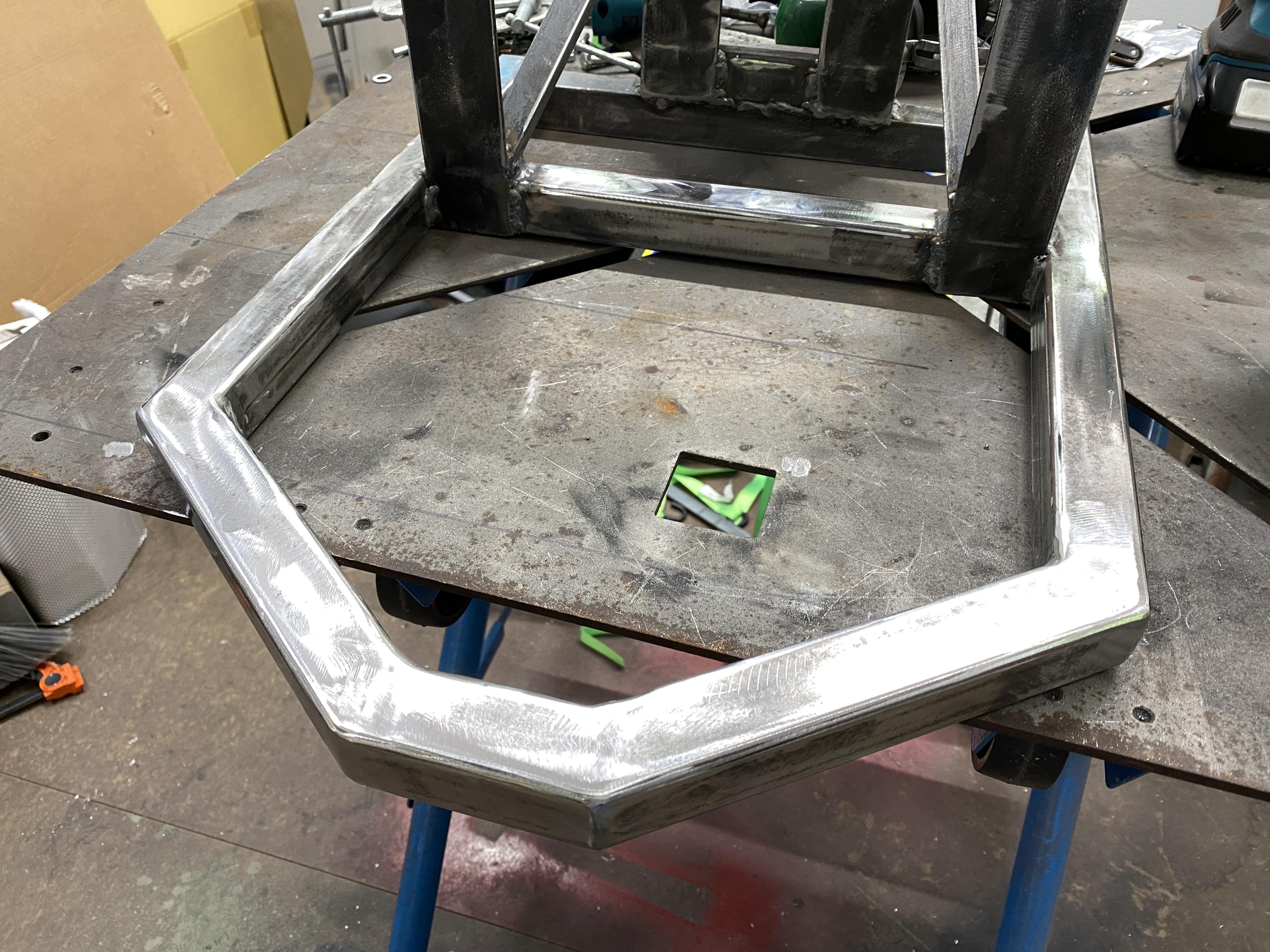
Front Bumper build & completed
Yesterday, as shown above, I had the base sub-assembly pretty much completed and was able to complete the actual bumper layout. I ended up using 1.25" sq tubing. I didn't go with round tubing since I didn't have a tubing bender and felt the square tubing made better angle cuts and cleanup. I first put a piece of cardboard under the nose of the radiator/grill assembly and made a trace of the nose. I cut 1.25" wide strips of paper, to act as the steel sq tubing, to layout on the cardboard trace to determine what I liked best. I then cut the strips of paper and used them as templates to layout on the sq tubing to make my cuts.
Below is the results of the cuts and laid out on my welding table. I first use a Sharpie to mark my welding table with the correct inside width and a centerline and position for the angle cuts. Once laid out, I then C-clamped the pieces to the table.

Once I tacked welded, I made a test fit to the chassis

This shot shows the test fit from the front. For me, it will provide the "warning" before I scrap the noise on a curb, etc.

After I was satisfied with the position, I tacked welded the bumper to the subframe I made. After the tack welds, I removed the 3 nut/bolts from the rear mount plate and the 2 control arm bushing nuts and the entire bumper assembly was easily removed for final welding. Take note I added my 3/4" angle iron bracing from the lower front section to the upper rear section.

Once welded, I then broke out the heavy duty grinder to make the welds disappear and look like one solid bumper. I'll clean and acid etch the assembly and get it painted with acid etching primer. I'll end up using flat black on the bumper assembly to help make it less visible. Using paint vs powder coating will allow for easy touchup when (not if) I bump into something.
I'm still not sure what's on the agenda today? So, you can be a little surprised tomorrow when I report out and update tomorrow. One item I'm thinking about is moving the radiator overflow tank to the left side of the radiator.... I saw on Walace18's build that's what he did and one less thing on the firewall.
Thx Mark
Last edited by mkassab; 05-19-2023 at 07:43 AM.
-
Senior Member
-
Senior Member
-
Senior Member
-
Post Thanks / Like - 0 Thanks, 2 Likes
-
Senior Member
Exhaust pipe clamp???
I had a few PMs asking about the "ring" looking objects on my exhaust pipes about 12" from the exhaust tips... i.e., what are they?
So, I thought I'd answer here for all. They are Mishimoto V-Band Clamps MMCLAMP-VS-25 purchased from Summit Racing. See pic below. The purpose is a quick disconnect at the V-Band. I had to installed them there to allow me to remove the exhaust later if needed vs cutting the exhaust pipes. I've used in the past and they work great with no leaks and no rust since they are Stainless Steel with a precision ring fit.
So my exhaust system is basically four sections.... 1) headers, 2) mid-section (H-Pipe/resonators), 3) rear-section (mufflers/loop tail pipe) and 4) exhaust tips.

Mark
-
Post Thanks / Like - 0 Thanks, 1 Likes
-
Senior Member
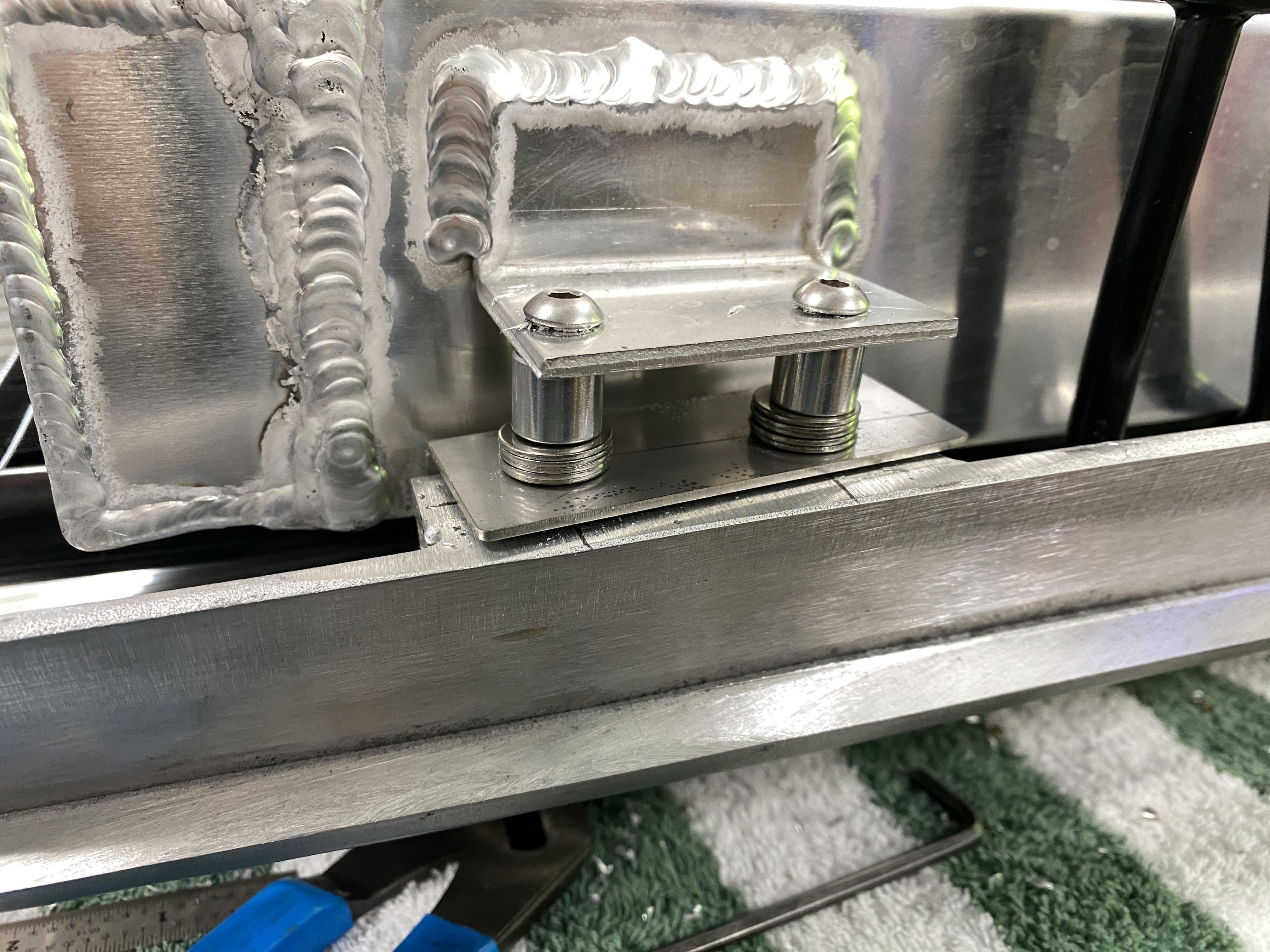
Air Bags/Springs Installed
Yesterday, I spent fabricating and installing the AirLift Air Bag/Springs. As you might recall in earlier posts, I had to wait to do this until I had the weight on the wheels and the truck bed on to determine where I had room to install them and not cause any interference. Now that those two conditions were met, I proceeded with the install. I bought some basic air bag/spring universal mounting kit and using scrap steel laying around the shop, I was able to complete the install.
First, I laid out on the axel some tape and marked the mounting points (so I can grind off the powder coat for welding the base plates) and I marked where the inter lip of the bed side was. A key point during the fabrication process was keeping in mind I had to be able to remove the air bags for any servicing/replacement and thereby, need access to the lower and upper mounting bolts. Since I didn't have a full weight load on the bed of the truck, I slightly compress the air spring without the top mounting plate to set the 2" angle iron against the bed frame and clamped into place to tack weld it.


This next picture shows the mounting plate setting on the axel with two 1" square tubes to raise the air spring off the plate to allow access to the two lower mounting bolts. On top of the sq tubing is the air spring base plate. When I complete all this, these three parts will all be welded together and to the axel.

After tack welding the top 2" angle iron to the frame, I compressed the air spring a little more to slip in the top mounting plate under the angle iron and tack welded it.

Since the upward forces could be pretty high, I added additional support framing to brace the top place. I used more 1" sq tubing and some 3/4" angle iron. Any upward force would then transfer through the 3/4" angle iron and the 2" angle iron to the truck's frame.

When I take everything apart to finish the frame painting, I finish welding all this add-on bracing.
I'm getting close to the point where I'll tear down all the installed items off the frame and then prep/paint the frame. To help me do this, I bought an additional engine mounting stand. I'll use the two engine stands, one attached to the front of the frame and one attached to the rear of the frame, for a makeshift rotisserie that will allow me to rotate the frame and make it a lot easier on me.
Stay tuned... much more to come.
Thx Mark
-
Post Thanks / Like - 0 Thanks, 1 Likes
-
Senior Member
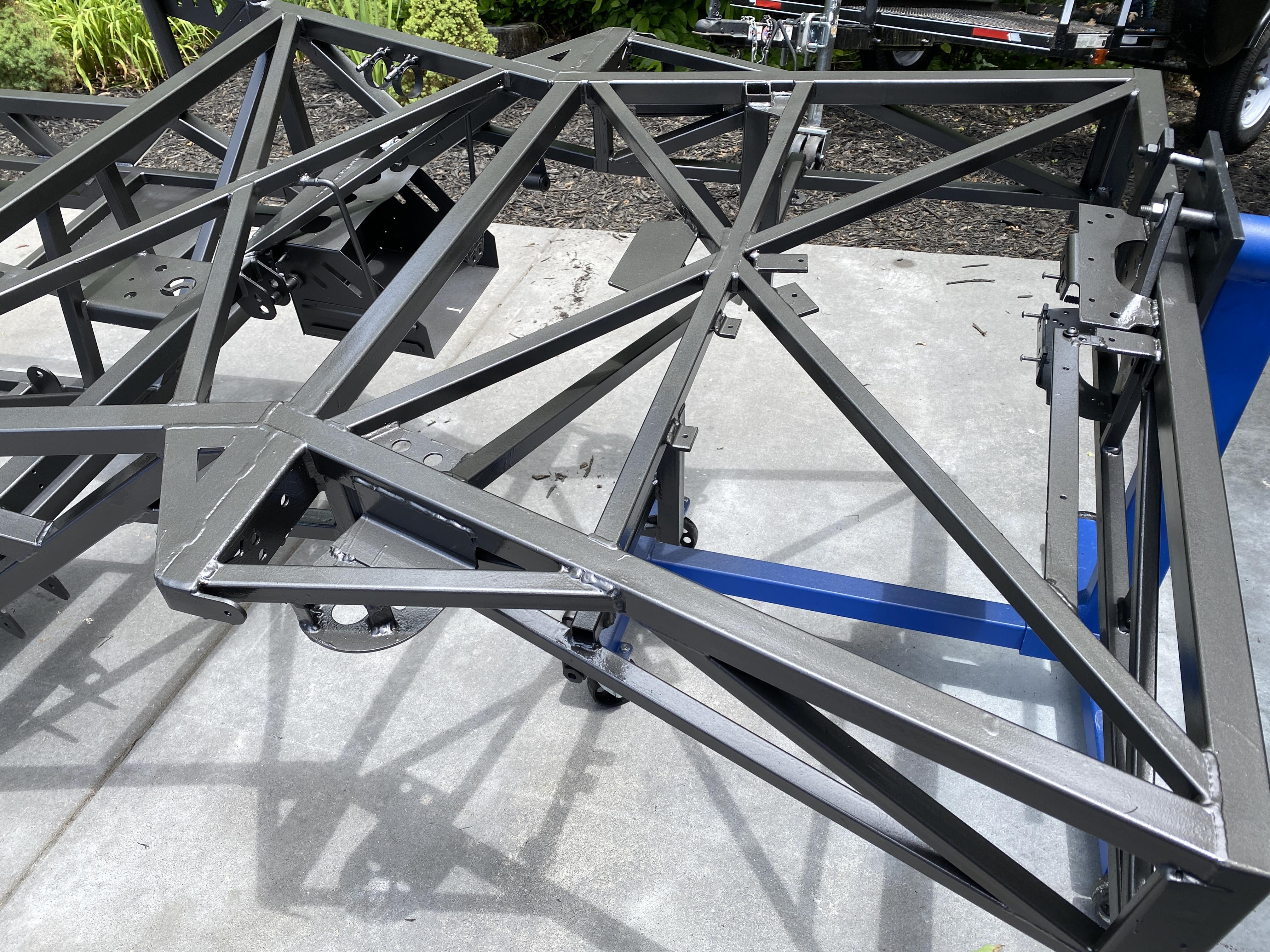
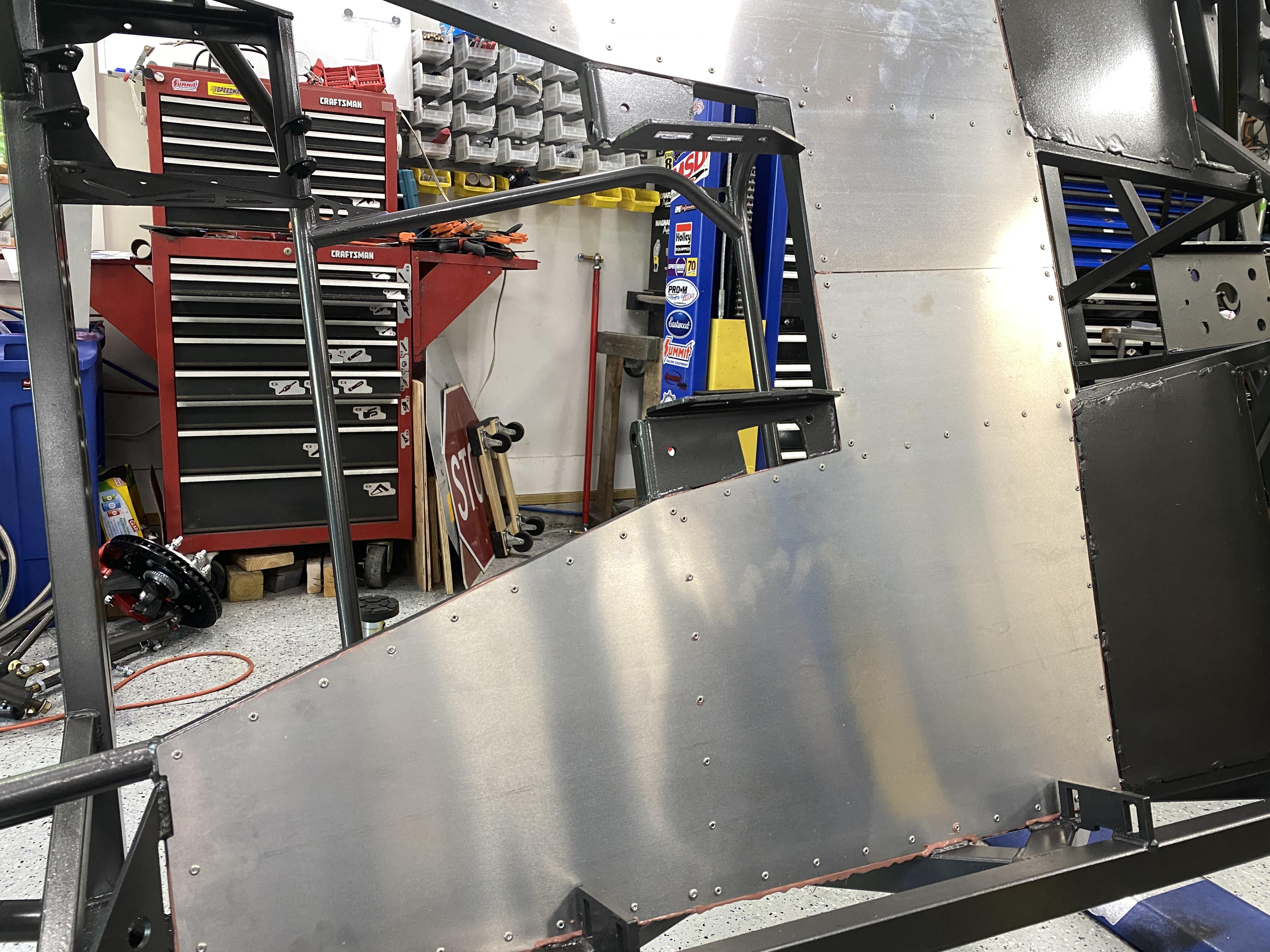
Disassembly to bare frame
Well, the disassembly of all the parts I've installed to date has begun. I believe I've completed all the fabrication/welding on the frame (i.e., hopefully I didn't forget anything!). If I did forget or overlooked something, I can always still weld, but would have some cleanup and repainting if needed. I can always try bolts/screws/rivets vs welding if it doesn't compromise quality or safety. What the disassembly did prove to me was I could take all this apart vary easily.... the picture below shows a lot has been removed from the frame and I only spent a few hours doing it myself, including the engine/trans removal. The only thing left to remove is the front suspension, cab and firewall. I know you can see the rear tires in the pic below, but if you look carefully, the rear-end/tires are off the ground and free of the frame (i.e., 3 point linkage a shocks disconnected) and the rear-end assembly sitting on jack stands.

My goal today is completing the disassembly and any remaining parts from the frame (including the cab) and the frame mounted to the two engine stands. This will allow me to finish all the welding followed by cleaning the frame, priming and paint. Once paint is done and cured well, I'll start putting it back together again.
Not looking forward to the above work, but getting it done will be a big milestone.
Thx Mark
-
05-27-2023, 06:13 AM
#100
Senior Member
-
Post Thanks / Like - 0 Thanks, 1 Likes
-
05-28-2023, 06:34 AM
#101
Senior Member
Rotisserie max swing/rotation
Not much to report on, except I did move the rear engine stand mounting point on the frame over ~5" from center..... this allows clearance for the truck's frame to clear the engine stand crossarm/leg. At this angle, the frame bottom will be very easy to work on, drill the holes for the bottom aluminum skin, etc.

The roll bar hitting the floor prevents full rotation. Also, to hold the rotation point, I had to rachet strap the roll bar to the lift's arm.

That's it for today. Cleaning and prep continue.
Thx Mark
-
Post Thanks / Like - 0 Thanks, 1 Likes
-
05-29-2023, 10:34 AM
#102
Senior Member
-
Post Thanks / Like - 0 Thanks, 1 Likes
-
05-31-2023, 04:26 AM
#103
Senior Member
-
Post Thanks / Like - 0 Thanks, 1 Likes
-
06-01-2023, 06:05 AM
#104
Senior Member
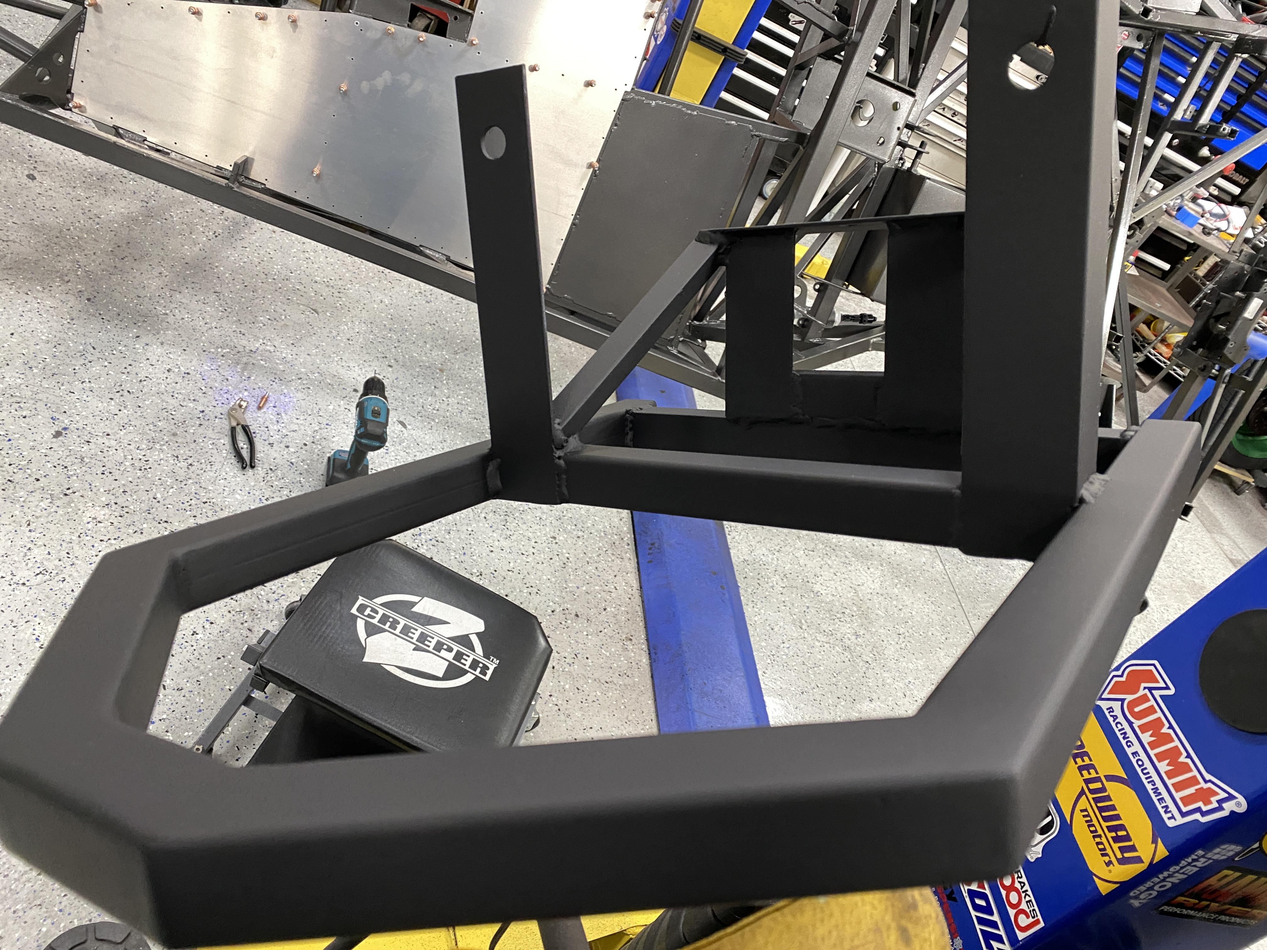
Frame Painted
I completed the frame painting using a rattle can over the POR15 and Primer. The color is Charcoal Metallic. It came out better than I thought for a rattle can. But like I've always said, I'm not building a show truck, but a daily driver.
Here's two pictures

Close-Up

I'll let it cure a few days now while on the engine stands before putting it back on the lift and starting the build. Perfect timing with the grandkids coming Sunday for the week.... however, I may be able to "sneak" some time in for the build? I do still have to clean-up the diff/rear-end and paint the Air Spring bases I welded on the axel tubes. Also, I have to paint the bumper I made, so I do have a few odds and ends to complete while the paint cures.... Not to mention the garage cleaning after all the paint dust on the floor.
Mark
-
Post Thanks / Like - 0 Thanks, 1 Likes
-
06-02-2023, 05:10 AM
#105
Senior Member
Baking in the Sun
Yesterday was a sunny day and since I had to clean the garage and put away some tools & get better organized, I set the frame out in the Sun to help the curing process. The frame's paint looked even better in the Sun, so I thought I'd post a couple of pictures.

While the paint continues to cure and still on the engine stands, I can rotate the frame that allows for good access to the underside to install the lower floor pan aluminum skins. So that's my goal for today.
Mark
-
06-03-2023, 05:44 AM
#106
Senior Member
Misc update, bottom skin started
I had a grand vision to get a lot done yesterday.... but events dictated otherwise. I did get the shop cleaned up a bit. I finished the welding and painting of the Air Spring based on the rear-end axel tubes.

I acid washed the front bumper I made with POR15 Metal Prep, primed with UPOL #8 acid primer and painted Flat Black.
I then started the drilling and mounting of the aluminum skin on the bottom of the frame. It's all drill and ready to go. Once I get the top skin drilled, I'll then apply bead of 3M Marine 5200 adhesive/sealer between the bottom skin and the frame and pop rivet in place. Followed by rolling the frame back to level and inserting the insulative panels with 5200 spread on both sides followed by the top skin sealed and riveted in place.

So, as stated above, today's focus will be completing the floor panels and insulative panels. If time permits, I'll get some other minor items installed while on the engine stands, e.g., rear oil cooler/fan, E-Stopp emergency brake, etc. I'm still waiting for my plastic gas tank cover from F5 from my MIK list.... so that's preventing me installing the tank. I also have to determine what I'm doing with the firewall panels... paint or clear coat, or what?
Stay tuned,
Mark
-
06-04-2023, 06:15 AM
#107
Senior Member
Floor top and bottom completed
Completing the floor.... here's what I did.
Bottom aluminum panels.... I drilled 1/8" holes every 2" for the bottom and then used the panels to act as a template to drill the frame. I did 2" spacing for the extra strength and water sealing qualities. Once all drilled, I removed the panels, cleaned them and the frame bottom... followed by applying 3M 5200 adhesive. I placed a pop-rivet in each hole first before any use of the pop-rivet gun. I have several Milwaukee battery tools already, so I picked up two additional tools only (no extra batteries or chargers), i.e., Pop-rivet tool and their Caulk gun. What wonderful time savers!!!

With the bottom panels completely installed, I'm able to rotate the frame to start the installation of the insulative rigid foam panels
This next pic shows the foam panels installed and me applying 3M 5200 to install the top aluminum panels using the same process I used to do the bottom panels (except, I place the rivets every 3" per the manual). Again, using the Milwaukee caulk gun was a huge time saver. The gun has settings for speed of the caulk coming out and auto backup of the plunger after you release the trigger.

Lastly, the top panels are completely installed.

A couple of side notes. You may have noticed two different colors of the 3M 5200. I had several tubes of a Mahogany color before I started using the white. Also, I plan to apply seam sealer on the bottom edges of the panels and over each pop-rivet as additional water sealer. I'll also coat the bottom panel with an undercoating of some sort.... I'm thinking of using some truck bed coating on the underside panels. I'll do this while the frame is on the engine stands for ease (on me) of applying the seam sealer and panel coatings. Once this step is completed, I can remove the engine stands and put the truck back on the lift.
I'll be selling the two engine stands and the two tall jack stands used to complete the exhaust since I have no use for them any longer and they take up too much room to store if I don't intend to use them again.
Grandsons coming tonight.... so updates may be limited over the next few days.
Stay tuned..... Mark
-
Post Thanks / Like - 0 Thanks, 1 Likes
-
06-04-2023, 08:41 AM
#108
Senior Member
I really like your use of two engine stands. 👍🏼
Wish Id had the same thought while building my 35 and would highly recommend what you did to anyone building an FFR that doesnt have access to a lift etc.
I finally got smart last year and did the same type of home built rotisserie for my latest Foxbody Mustang project. Same issue you had
couldnt totally invert the bare body but it was a total game changer for me.
Congrats on the great progress with your build.
Cheers
Pat
Once again with an 88 mm Turbo, Big Block Chevy powered, 35 Hot Rod Pickup
-
06-05-2023, 05:52 AM
#109
Senior Member
Originally Posted by
Pat Landymore
I really like your use of two engine stands. ����
Wish I’d had the same thought while building my ‘35 and would highly recommend what you did to anyone building an FFR that doesn’t have access to a lift etc.
I finally got smart last year and did the same type of home built rotisserie for my latest Foxbody Mustang project. Same issue you had…couldn’t totally invert the bare body but it was a total game changer for me.
Congrats on the great progress with your build.
Cheers
Pat
Thanks Pat
Mark
-
06-05-2023, 06:20 AM
#110
Senior Member
Floor sealed and undercoated
Good day yesterday. I finished the underside seam sealer and truck bed undercoating. That allowed me to remove the two engine stands from the frame and the frame is now back on the lift and ready to reinstall all the parts I took off it.
First, I cleaned, scuff padded and sanded the bottom aluminum skin before applying the seam sealer and undercoating. I seamed sealed all seams top and bottom (including the FF welded in sheet metal bottom floor pans) and the bottom pop-rivets caps.

And the rear sheet metal pans

For the top skins, I seamed sealed the center seam and the outside left & right including the large cutouts for the frame welds

Lastly, I mixed the 2 part epoxy truck bed liner (U-POL Raptor bed liner product) used for the undercoating and put on two thick layers to get to the correct mil thickness. Not only will this protect the bottom from any corrosion, but also help with sound and heat. Later in the build, I'll apply Lizard Skin sound and heat to the inside of the cab (i.e., floor, firewall, doors, rear of cab and the cab itself). I'll also add a layer of other sound/heat sheet material (butyl rubber and aluminum stuff).

Today.... start reinstalling the suspension, etc.
Mark
Last edited by mkassab; 06-10-2023 at 05:43 AM.
-
06-09-2023, 07:08 AM
#111
Senior Member
With the grandkids here, I've had limited time to work the truck build... but they do sleep in and I get out a couple hours each morning..... Today, they fly back home to Florida.
I have the rear-end, 3 point linkage and shocks reinstalled, the entire front suspension reinstalled and starting the firewall. I cleaned, scuffed, primed and painted the aluminum firewall a bright silver (pic below). I'm working the engine bay while the engine is out for easy access to installed "stuff", e.g, brake lines, brake rear bias control, etc.

So, a lot more to share coming soon.
Thx Mark
-
06-10-2023, 05:42 AM
#112
Senior Member
Brake Pedal Box, brake fluid connection, raw steel steering column
Good day yesterday.
First up, I ordered a raw steel steering column with my '35 truck order and my intension was to paint it the same color of my wheels and the body beltline. However, the raw steel had a nice brush finish to it.... so I just used a red 3M scotch pad to freshen it up and cleaned with acetone. I used VHT ceramic disc brake clear gloss to brighten it up and seal the steel to protect from corrosion. It came out great.

On the firewall side, I have the WilWood brake bias installed and plumbed to the master cylinders. I also completed the plumbing of the brake fluid reservoir to the master cylinders. For both the brake lines and brake fluid lines through the firewall I used 3AN bulkhead fittings for the brake lines and 5/16" barb bulkhead fittings for the brake fluid reservoir connections vs just drilling holes and running the hoses through the firewall holes. You'll also take notice I made some brake/master cylinder bleed lines from the output of the brake bias unit back to the brake fluid reservoir. I used the steel lines FF supplied for this purpose. This way, when I "bench" bleed the master cylinders I'll also be bleeding the brake lines and brake bias at the same time. I'll also run a line from the clutch master cylinder to the reservoir. When I get the trans/engine back into the chassis, I'll run a line from the clutch slave cylinder throw-out bearing to the reservoir to bleed the slave cylinder.

The next 3 pictures are the brake pedal/master cylinders setup/plumbing. It was much easier doing all this with the cab off the frame. I was able to connect and tighten everything with ease and also ensure no hose was near or rubbing any moving part. I used zip-ties to keep things tight.

Top view showing a little more detail

Bottom view showing pedals and hoses

Today, I'll connect the oil cooler, oil thermostat, remote oil filter to be ready for the engine install. I'll also connect the lower firewall panels to the top aluminum floor panel with 3/16" pop-rivets and then seam seal them. The steering column will be installed along with other misc items. I need to make a clutch pedal adjustable stop while I have easy access to this area.
More to follow,
Mark
-
06-11-2023, 06:44 AM
#113
Senior Member
Misc & Clutch Pedal Stop
Quick update.
I fastened both the left and right sides floor pans to the lower firewall sections with Five each side 3/16" pop-rivets. I clamped them together then drilled for a good firm tight fit.

I then Seam Sealed both the tops and bottoms. While I had the seam seal out, I also applied seam seal on the inside of the firewall around the frame holes (that go through the firewalls) and the sq tube area on each side of the floor pan/fire wall panels. Obviously, my goal, when the cab is 100% complete, is to have an Air and Water tight sealed compartment.

Lastly, for my Clutch Pedal stop (that's adjustable in/out) I chose the spot just behind the clutch pedal and below the frame cross member. I would have liked to drill and tap the cross member, but my FF serial number is there. It's a very simple setup... i.e., 3/8" x 2.5" socket head with a jam nut/washer on the inside of the firewall and a nylon-lock nut/washer on the outside. Since my Hydraulic Clutch Slave cylinder can only be extended to a certain point, this pedal stop is required. Also, notice my serial number.... after I POR-15'd and painted the frame, I sanded the area where the serial number is and then clear coated that area. Therefore, this area is protected from rust and the serial number is highlighted for easy viewing.

Stay Tuned
Mark
-
06-12-2023, 05:18 AM
#114
Senior Member
Oil Line and Oil system pressure test & bed frame template
I made a lot of misc odds & ends progress yesterday... most of which isn't "Post" worthy. But I did want to share two items that may help others with ideas towards their builds.
First up, with my Oil System (i.e., 5 hoses, remote oil filter, oil thermostat and oil cooler/fan) all connected, less the two engine in/out connections, I proceeded to pressure test the system for any leaks. I bought these two AN10 plugs (with one of the plugs having an air valve stem installed). The Plug goes in one of the two hose fittings and the Air Plug in the other. I put 80 psi in the system and I checked the air pressure several times over several hours to make sure is was holding. I'm happy to say, it passed the test. I'll do the same with the fuel lines and gas filters when it comes time.
Picture of the two plugs installed

Second up, I made a paper template of the bed frame. The reason I did this is to help be determine the mounting points of the stainless steel bed provided in the FF kit and the aftermarket BedWood system I'm installing. My plan is to install the ss bed sheet is such a way I can easily remove it in case I have to get access to the oil cooler/fan, gas tank senders, E-Stopp emergency brake, etc. I'll need to determine the ss bed sheet mounting points to the frame.... I'll do this by laying the paper template on top of the ss bed sheet and taping it down in place. Then, I'll lay out the BedWood frame on top of the paper to transfer the mounting points to the paper. I want the BedWood system to be mounted firmly, but also easily removeable. I'll document all that later in this build thread. I also plan to have the gas filler mounted on the right rear fender vs the bed floor. FYI.... I did received my BedWood system two weeks ago. It took about 6 weeks to receive after I ordered it. And because our truck beds aren't a standard size, it had to be custom built. I ended up ordering the Black Walnut wood with polished SS ribs/hardware and I also ordered some extra Black Walnut for 4 posts and bed rails (I still need to determine how to mount the posts to the bed side walls). I also ordered my wood unfinished as I plan to apply 2K auto grade gloss clear coat to the wood. Using 2K auto clear provides the best protection to the wood with it's UV protection in the clear. It also makes it easy to sand and buff to get the best polish shine just like it would on the truck's body. I'll just use the same polish/synthetic ceramic coatings on the wood that I use on the truck's paint. The Black Walnut should go very well with the pastel light green I'm painting the truck.

More to follow, so stay tuned and subscribe to this thread if you haven't already subscribed.
Thx Mark
-
06-13-2023, 07:23 AM
#115
Senior Member
Wheel Spacers & Brakes lines installed and bled
I received my 3/4" front and rear wheel spacers. While installing them, I first had to determine how much length to cut off the stock lug bolts.... in my case, I had to cut ~5/8" using my angle grinder cut off wheel. I then installed all four and torqued each lug nut to 90 ft lbs.

The next job took me several hours.... I finished my brakes.
I first "bench bled" the three master cylinders as I outlined above in a recent previous post. Then I installed all the brake lines I made earlier. I still had to make the front right and left brake lines, which I did. Once all brake lines were installed at a four corners and the two front line and the single rear line were setting loose/unconnected at the WilWood brake bias unit, I was ready to disconnect the brake bleed lines I made from the brake bias unit one at a time (Note: this is the messy part, i.e., once you disconnect a brake bleed line, gravity kicks in and the brake fluid starts to run out of the brake bias unit). So, with rags at hand and a small catch can, I first removed the rear bleed line to connect the "waiting" rear brake line. Trying to be quick, with very slippery brake fluid all over my fingers, I got the rear line connector threads started and tighten. I then proceeded to the first front brake line followed by the other front brake line.

Rear brake line junction... i.e., the main brake line runs to the Brake Line Lock, then to a T-fitting, and then to the left and right brake calipers.
(Note: the two ss braided hoses you see are the oil cooler in/out lines to/from the oil thermostat)

From this point, I bleed the brake lines at all four corners, starting with the right rear (longest run from the master cylinder), then to the left rear caliper. Followed by the front right then the front left. I'll bleed again before my first drive.
Check in tomorrow for todays activities.
Thx Mark
-
06-13-2023, 12:06 PM
#116
Senior Member
Drive Shaft Too Long !!!
Big bummer today.... I got the engine/trans back in the chassis. Went to install the drive shaft for the first time and BAM... Screenshot 2023-06-13 130445.jpg the fricken thing is too long.
I sent this note to Madison and Dan G at FF:
Hi Madison and Dan,
I finally got to the stage to install my drive shift.
BTW, here's the link to my truck build thread on the ff forum:
https://thefactoryfiveforum.com/show...w-Gen-3-Coyote
Ref the two attached pictures.... pic 1 (2223) shows the drive shift yoke bottomed out in the trans and pic 2 (2224) shows the rear-end diff end being ~1.5" too long. Given the yoke wouldn't be bottomed out against the transmission for the final install.... so that would make the drive shift about ~2.5"+ too long.
When I measured the center of the front universal joint cap to the center of the rear universal joint cap on the drive shaft it measured ~39.5". I'm thinking it should be about ~37" center to center u-joint cap?
Again, ref my order, I have the Gen 3 Coyote eng, Quicktime Bell housing and the Tremec 6-speed Magnum transmission model #11010
IMG_2223.jpg
IMG_2224.jpg
I'll update once I hear from FF
Mark
-
06-14-2023, 04:31 AM
#117
Senior Member
Coyote Engine and Trans installed
A major milestone was passed yesterday.... the Coyote Engine and Tremec Magnum 6-spd trans back in the chassis and installed. As I mentioned in the above post, the drive shaft shipped with my kit was too long and I'm waiting on FF's response. I did get the Clutch master cylinder connected to the Tilton Hydraulic throw-out bearing and bled. While doing this process, I also set my Clutch pedal stop and confirmed the Coyote clutch switch (that came with the Ford Performance ECU kit/harness) is engaged with the clutch pedal is depressed.
This first pic shows the engine smoothly gliding back in place. This is really a easy step for one person (i.e., me) to do. The engine hoist with the engine tilt device makes easy work of it all. I use a ratchet strap on the tail of the transmission to help guide and keep the trans/engine straight.

Here's a shot of the back of the engine and the wire harness neatly tucked away within the various engine components. I zipped tied them in place as you see it.
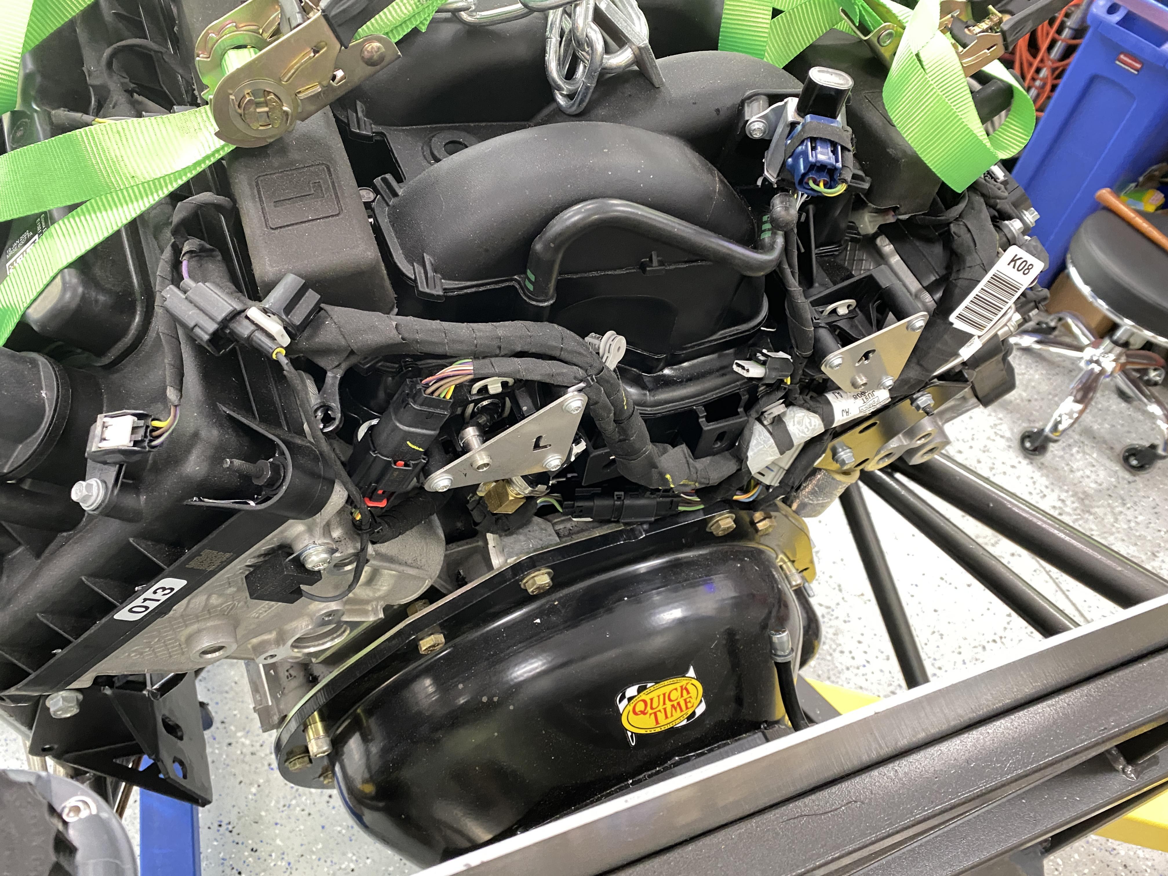
And this last picture shows the clearance between the firewall and the engine..... It's a good 1" of space.

I plan on this being the final install, i.e., I'm not removing the engine / trans again.... at least that's the plan.
Today.... I'll focus on connecting the steering components, power steering drive, oil lines to the engine, fuel pressure regulator and fuel line to the engine, Headers/exhaust installed, Headers wrapped with heat tape, etc. Once the exhaust is installed, I can finish the rear-end install with the Panhard Bar and Air Bags. I can't install the gas tank yet as I'm still waiting on a backordered gas tank bottom cover from FF. With any luck, I'll have the tank cover in a couple weeks.... or it could be a couple months according to Madison at FF.
As I write these posts, I realize just how much more I have to do... e.g., A/C System & hoses, electrical, Heater hoses, radiator/hoses/coolant, etc. All good stuff.
Later,
Mark
-
Post Thanks / Like - 0 Thanks, 1 Likes
-
06-15-2023, 05:27 AM
#118
Senior Member
-
Post Thanks / Like - 1 Thanks, 1 Likes
-
06-16-2023, 06:08 AM
#119
Senior Member
Headers Installed and E-Stopp Emergency Brake conntected
As I mentioned in the last post, I coated the header wrap with a DEI Silicon Heat/sealer product.... this is it.

In preparation for the header install, I added a ss washer to each Stage 8 Header bolt, coated each bolt with anti-seize. For those not familiar with Stage 8 I'd suggest a quick Google. Bottomline, Stage 8 offers different types of locking devices, i.e., once a bolt is installed and torqued, you add a locking tab to the bolts end that prevents it from backing out/loosening. Great product as I've used them for every build I've ever done.

I installed the left (drivers) side header first. No problems as it slipped in easily from under the frame and up to the install position. The headers in the pictures are all coated with the DEI Silicon product. I was able to get my torque wrench on 6 of the 8 bolts using various methods, e.g., straights socket, swivel head socket, crows foot. The other two with a combination of allen wrench ball head (i.e., each Stage 8 bolt head is a 7/16" and a 5/32" hex head) and/or various wrenches. I had to do my best by hand to torque as the torque wrench wasn't an option. The wrap thickness didn't help matters at all.

Next was the right (passenger) side header. Well, the wrap thickness prevented the header from slipping in..... so, I had to remove the engine mounts on both sides and jack up the engine using my floor jack to lift the engine up about 1.5" to get the header in. I placed a piece of 3/4" plywood on the bottom of the oil pan to spread out the load. It was a lot of extra time consuming work, but it all worked out. Also note the top engine mount bolt.... for extra clearance with the header pipe, I ground down the bolt head by 50%.

To finish out my day, I ran and installed the emergency brake cables to the E-Stopp electronic emergency brake unit and connected the cable ends to the connection block with set screws. I also add a cable clamp for an extra secure connection.

Today, the rear section of the exhaust still needs final welding. Then the exhaust will get installed, along with ???? (haven't made my mind up yet).
Thx Mark
-
06-17-2023, 05:32 AM
#120
Senior Member
Exhaust welded, installed & insulated
I finished welding up my exhaust system and now have it all installed. At each joint where two parts meet, I used Permatex Ultra Copper infused RTV High Heat Silicone.... i.e., This Permatex Ultra Copper RTV silicone adhesive is designed to provide a waterproof, flexible, weather-resistant seal around metal. It's designed for temperatures of up to 700 degrees F. It's just one more step to help ensure a sealed, no leak, exhaust system. I lightly tighten the nuts/bolts.... let the silicon set for a day and then tighten all the way. This helps preventing a lot of Silicon from squeezing out of the joints.
I provided a few pics of all the exhaust pipe/muffler insulation to help further reduce heat/noise from entering the cab to supplement the header wrap. I applied the foil backed fiberglass insulation from the header collector back and over the mufflers under the truck bed.


I suspect many of you will think this is an overkill, and it may be, but this truck is intended to be my daily driver, not a show car, and I want as much sound/heat insulation as possible.
Today, while under the truck, I'll fasten the brake lines, oil lines, etc with line clips. And even though I can't install my gas tank yet, since I'm still waiting for the bottom gas tank cover from FF, I'll run the gas lines (fuel supply and the return line) from the engine back to the tank and get them clipped in place. I guess while I'm at it, I'll run the battery cables also.
Stay tuned.... more to come,
Mark
-
Post Thanks / Like - 0 Thanks, 1 Likes


 Thanks:
  Likes:


 Reply With Quote
