FormaCars

Visit our community sponsor

Thanks Thanks:  0
Likes Likes:  5
Page 8 of 51 FirstFirst ... 67891018 ... LastLast
Results 281 to 320 of 2016

Thread: More progress made on the body : )

  1. #281
    Senior Member The Stig's Avatar
    Join Date
    Feb 2011
    Location
    Charlotte, NC
    Posts
    2,004
    Post Thanks / Like
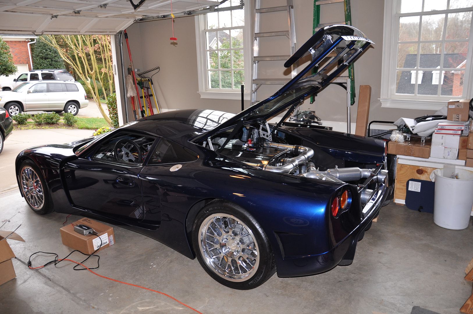
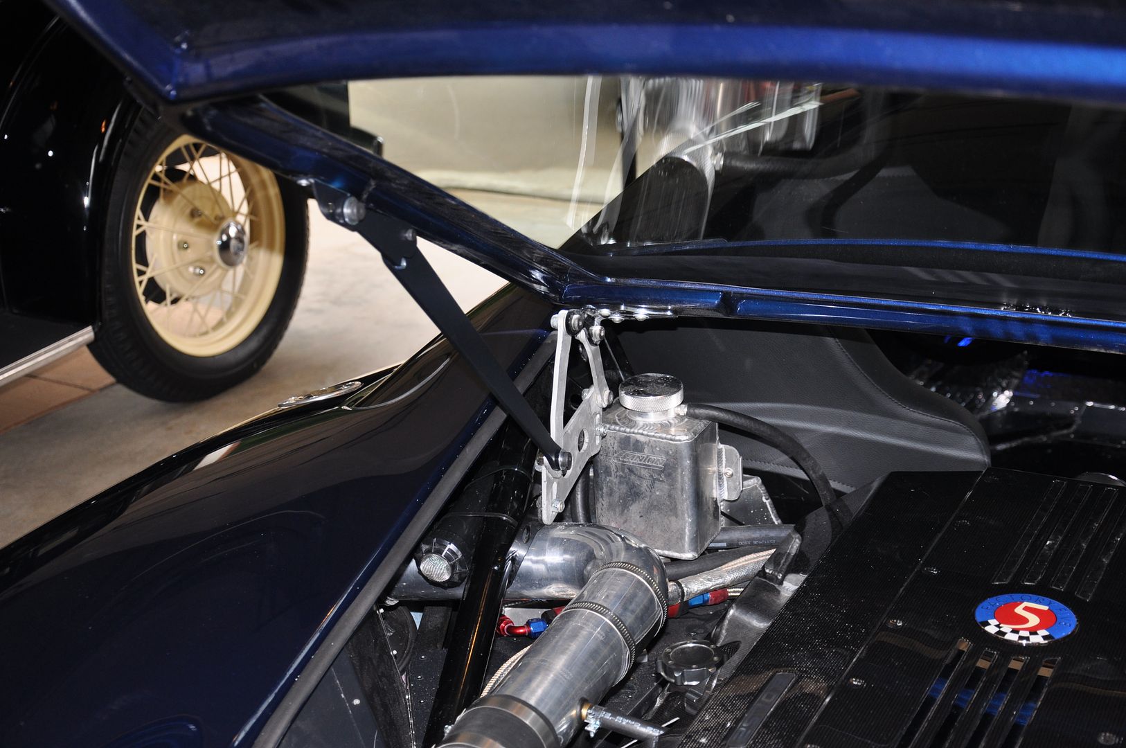
    Thanks Rick. I appreciate it. Understated Elegance as a wise man once said... The look of the car is really turning out the way I had hoped.

    Take Care,

    Mike
    The Stig

    Some say, that I only know two facts about ducks, (both being wrong); and that if I could be bothered, I could solve the "da Vinci Code" in 47 seconds...
    All I know is that I'm called "The Stig".
    GTM #0081

  2. #282
    Member
    Join Date
    Jul 2011
    Posts
    35
    Post Thanks / Like
    Looks great Stig! Congrats on getting her back home.

  3. #283
    Senior Member The Stig's Avatar
    Join Date
    Feb 2011
    Location
    Charlotte, NC
    Posts
    2,004
    Post Thanks / Like
    Quote Originally Posted by Stage7 View Post
    Looks great Stig! Congrats on getting her back home.
    Thanks Roberto. It feels good to have it back in the garage!
    The Stig

    Some say, that I only know two facts about ducks, (both being wrong); and that if I could be bothered, I could solve the "da Vinci Code" in 47 seconds...
    All I know is that I'm called "The Stig".
    GTM #0081

  4. #284
    Senior Member The Stig's Avatar
    Join Date
    Feb 2011
    Location
    Charlotte, NC
    Posts
    2,004
    Post Thanks / Like

    Seat Belt Harness Bar Mounting

    How many have used racing harnesses attached to a harness bar? I have Richard Oben's Harness bar, and I'm wondering whether or not just bolting it through the frame bars is sufficient? Or would a bracket be a good idea to have behind the bar?

    I'm also considering either having the bar Powder Coated, or send it out the be Chromed/Polished. What are your thoughts?
    Last edited by The Stig; 12-20-2011 at 02:27 PM.
    The Stig

    Some say, that I only know two facts about ducks, (both being wrong); and that if I could be bothered, I could solve the "da Vinci Code" in 47 seconds...
    All I know is that I'm called "The Stig".
    GTM #0081

  5. #285
    Senior Member
    Join Date
    Feb 2011
    Location
    San Diego
    Posts
    1,965
    Post Thanks / Like
    IMHO...you should make the shoulder belts attachment points as strong as you can. If there is a way to make it stronger with minimal changes/work...DO IT!

    But that's just my opinion.
    www.myraceshop.com

    GTM solution kits
    Corvette and Race parts

  6. #286
    Senior Member
    Join Date
    Feb 2011
    Posts
    119
    Post Thanks / Like
    I thought about chroming too, but it would have been the only chrome interior item...I decided to do a satin black powder coat that blended well. I am bolting through the existing frame, grade 8 hardware...at this point, I am not doing anything more.

  7. #287
    Senior Member The Stig's Avatar
    Join Date
    Feb 2011
    Location
    Charlotte, NC
    Posts
    2,004
    Post Thanks / Like
    Filters for the fuel tanks:

    I saw a filter that Gary Cheney used for what looks like a gearbox breather. I would like ot do something similar for each of my fuel tanks. If you look at the picture you'll see a cone shaped filter mounted to the right hand sided of the engine bay framework. I am looking for a way to allow the tanks to breathe, and also vent the fumes safely away from the car.

    I'm thinking of using something like this, unless anyone knows where I could find a charcoal filter that I could vent through.

    Also, where is a good place to find the filter that Gary used in this picture? Is this a Summit part?

    Thanks,

    Last edited by The Stig; 12-27-2011 at 11:31 AM.
    The Stig

    Some say, that I only know two facts about ducks, (both being wrong); and that if I could be bothered, I could solve the "da Vinci Code" in 47 seconds...
    All I know is that I'm called "The Stig".
    GTM #0081

  8. #288
    Senior Member weendoggy's Avatar
    Join Date
    Feb 2011
    Location
    Aptos, CA
    Posts
    408
    Post Thanks / Like
    You can make an inexpensive charcoal filter yourself by using a 4" yard popup sprinkler, gutted, sink strainer and charcoal for an aquarium. A lot of us are doing that on our roadsters and they work quite well. You could probably hide it from your engine bay for a clean look too.
    I'm just a victim of a thousand physic wars!
    www.weendoggy.com/cobra.htm

  9. #289
    Senior Member The Stig's Avatar
    Join Date
    Feb 2011
    Location
    Charlotte, NC
    Posts
    2,004
    Post Thanks / Like
    Thanks Glenn. Do you have any pictures of that process? If I can make it myself, I'd like to give it a shot.

    Mike
    The Stig

    Some say, that I only know two facts about ducks, (both being wrong); and that if I could be bothered, I could solve the "da Vinci Code" in 47 seconds...
    All I know is that I'm called "The Stig".
    GTM #0081

  10. #290
    Senior Member weendoggy's Avatar
    Join Date
    Feb 2011
    Location
    Aptos, CA
    Posts
    408
    Post Thanks / Like
    Check this thread http://www.ffcars.com/forums/17-fact...al-filter.html and look at post #5. I made mine similar to this but did some extra things.
    1. Take the guts out, go to a pet store and buy a small box of charcoal (usually in pellet type), get some fine SS mesh screen from a hardware store in the sink stopper area and a small 1 1/2" sink strainer.
    2. After taking the guts out, check to make sure the sink strainer will fit (I did this in the store to make sure it would), open up the thread top to allow a little extra breathing room (I just used a knife)
    3. Cut the fine mesh screen (mine was from a SS strainer I cut from a store bought strainer) large enough to fit in the sprinkler body but not come out the threaded end, cut another one to fit just under the sink strainer to keep the charcoal from coming out.
    4. Put the small piece in the bottom, fill with charcoal, put the second fine mesh and sink strainer on followed by the screw top.
    5. Now all you need is a 1/2" NPT to hose size of your choice on the end of the sprinkler and you can install. I secured mine with a large loom insulated clamp.

    Picture of mine installed.
    Attached Images Attached Images
    I'm just a victim of a thousand physic wars!
    www.weendoggy.com/cobra.htm

  11. #291
    LCD Gauges's Avatar
    Join Date
    Apr 2011
    Location
    Toronto, Ontario
    Posts
    1,545
    Post Thanks / Like
    Blog Entries
    3
    K&N makes various types of breathers. The one in the following photo is about two inches in diameter, and can be purchased for about $15.00.

    They even come with chrome caps:

    [IMG]http://www.jegs.com/images/photos/50...-62-1470_4.jpg[/IMG]
    599-62-1470_4.jpg
    Custom LCD Gauges , Data Loggers, Control Touch Screens
    www.LCDdash.com \\ 647-522-9953 \\ Voice & Text
    Proud new owner of GTM Gen 1., #105 - 08/27/11
    LQ9 Powered, G96.00 6 speed transaxle

  12. #292
    Senior Member The Stig's Avatar
    Join Date
    Feb 2011
    Location
    Charlotte, NC
    Posts
    2,004
    Post Thanks / Like
    I am getting ready to do the alignment on my car, but thought that since I'm doing that, I should go ahead and make the suspension changes that I had been thinking of (at the same time). I don't like pulling the corners apart. Especially the shocks.

    1. Have the upper and lower control arm mounts and the Upper Shock mounts relocated.
    The Upper C/A mounts moved rearward 1/2 inch, and The Lower C/A mounts moved forward 1 inch. This should reposition the wheel in the fender opening to give more clearance for there rear of the fender. My "guesstimates" look like it should move the hub forward by about 3/4 inch.

    This is based on my guess that the uprights are roughly 14" tall. (Guessing because I haven't had time at home to put a tape next to them to measure more accurately, but will soon.) My thinking is that if I move the top mounts rearward without moving the lower, I'm going to crowd the rear of the fender even more. So, in order to get some of the caster that I need, and keep the front wheels centered in the wheel openings, I'm planning to go with the last model pictured.


    2. Rebuild the arms using Pfadt C5 Control Arm "Poly" bushing kit. (I'm also thinking of having them powder-coated as well, but not sure yet).


    3. The upper shock mount will more than likely need to be relocated in order to center the shock between the Upper Control Arms.
    4. Replace all shocks with Penske 7500 dual-adjustable.

    5. I want to use Ted Harrison's (LS Man) Anti-Roll bar Kit on the front suspension.
    Doing so means that I'll have to give up the custom aluminum Wiper Mount, Wiper Fluid container, which sort of bums me out because it's such a nice piece.
    I'm am still kicking around the idea of using a stock corvette bar on the front as well. (But I really like the design that Ted has come up with.)
    I can install Ted's bar kit without needing to remove the aluminum panels for access. Just drill the needed hole, and slide the torque bar through.
    Everything else bolts on within the wheel opening.

    6. I'll be using a standard "Medium" Corvette bar on the rear suspension. Pfadts "JO" Bar. Standard bar and links can be used.

    7. Then the alignment and weight balancing can begin.


    I think that I am finally about to free up some time that I can start working on the car again. Given my schedules lately, this may end up being a 3 weekend project.

    In the meantime, I think I may finally be able to get the registration and plates behind me, and get it out on the road soon. We'll see. I'm just glad to finally have a plan, and some time to pursue it again.

    I don't have scales to weigh the car, so I'm looking into buying a set of Longacre (4400 x 1 lb.): around $800.00.
    I've purchased the alignment "flats" for toe-in measurement. $60.00
    Getting ready to buy a Camber/Caster gauge as well.

    Please send your thoughts. Particularly on the C/A bushings. I don't want it to ride like a tank, but I do want to keep the arms "static" so the alignment doesn't move around much due to loads.

    We'll see how it works out.
    Last edited by The Stig; 01-09-2012 at 11:42 AM.
    The Stig

    Some say, that I only know two facts about ducks, (both being wrong); and that if I could be bothered, I could solve the "da Vinci Code" in 47 seconds...
    All I know is that I'm called "The Stig".
    GTM #0081

  13. #293
    Senior Member
    Join Date
    Feb 2011
    Location
    San Diego
    Posts
    1,965
    Post Thanks / Like
    You're really going to buy an $800 set of scales to use once or twice?

    DANG!
    www.myraceshop.com

    GTM solution kits
    Corvette and Race parts

  14. #294
    Member
    Join Date
    Feb 2011
    Location
    Ft. Lauderdale
    Posts
    45
    Post Thanks / Like
    I wonder how much caster you'll be building in by altering the angle by 1" & 1/2" (option 3)? More than you want? How much do you want? On my upper control arms I moved the balljoint pickup point back about 1" (caster) and in some as well (camber) as best as I can tell I can get 7* of caster and -2.5 of camber fairly easily. Should be easy to get more caster if I wanted (front lower rear adjuster only out 1/2 way). Please keep in mind my measurment devices are kind of crude so your mileage may vary. My initial though might be do 1/2" either way (option 1). I would imagine moving those lower mounts would be quite a job though. Too bad you couldn't machine off a little of the fronts of the lower control arms and the new bushings so it would move forward a bit,, then just shim the backside.

    I bet Joel could tell you what you'd be looking at with those new numbers,, maybe he'll post up his thoughts.

    I've got VBP polly bushings in mine. Based on everrything I've read, they will probablly squeak after a time. I put zerk fittings in the front lowers as the new bushings are two pieces an hopeully I can get some lube in there where they start making noise.
    Fred

    ----------------------------------------------------------------------------------------------------------------------------------------
    GTM #22 - Worlds slowest build

  15. #295
    Senior Member The Stig's Avatar
    Join Date
    Feb 2011
    Location
    Charlotte, NC
    Posts
    2,004
    Post Thanks / Like
    Quote Originally Posted by crash View Post
    You're really going to buy an $800 set of scales to use once or twice?

    DANG!
    Unless I can find some that are less expensive; yes. I don't have direct access to a "race shop" to make the changes that I need to make, or to scale the car. If I find that I don't need them later, I'll sell them.

    Quote Originally Posted by Fred Brewer View Post
    I wonder how much caster you'll be building in by altering the angle by 1" & 1/2" (option 3)? More than you want? How much do you want? On my upper control arms I moved the balljoint pickup point back about 1" (caster) and in some as well (camber) as best as I can tell I can get 7* of caster and -2.5 of camber fairly easily. Should be easy to get more caster if I wanted (front lower rear adjuster only out 1/2 way). Please keep in mind my measurment devices are kind of crude so your mileage may vary. My initial though might be do 1/2" either way (option 1). I would imagine moving those lower mounts would be quite a job though. Too bad you couldn't machine off a little of the fronts of the lower control arms and the new bushings so it would move forward a bit,, then just shim the backside.

    I bet Joel could tell you what you'd be looking at with those new numbers,, maybe he'll post up his thoughts.

    I've got VBP polly bushings in mine. Based on everrything I've read, they will probablly squeak after a time. I put zerk fittings in the front lowers as the new bushings are two pieces an hopeully I can get some lube in there where they start making noise.
    Hi Fred. I posted the drawings more or less to get feedback, to find out if my logic is pointed in the right direction or not. All I know for certain is that I do NOT want to cut into the body to grind out some wheel clearance for the front wheels. So I figure that top and bottom arms need to be in the equation. Without having specific measurements of the uprights, and where the dimension of the center-point of the hub is, relative to the overall height of the part, I'm just guessing at best.

    There was talk of custom upper control arms that could be made for the GTM builders. But there doesn't seem to be a lot of interest for those who could to make them. Fran Hall makes some beautiful billet arms for his cars, but I'm fairly certain that he is not in the business of creating workable arms for the "competition". You can look in just about any parts catalog, and see adjustable control arms for mustangs: But absolutely nothing for the Corvette C5 or 6.

    So, for me, this appears to be the next best thing.
    The Stig

    Some say, that I only know two facts about ducks, (both being wrong); and that if I could be bothered, I could solve the "da Vinci Code" in 47 seconds...
    All I know is that I'm called "The Stig".
    GTM #0081

  16. #296
    Member
    Join Date
    Feb 2011
    Location
    Ft. Lauderdale
    Posts
    45
    Post Thanks / Like
    Quote Originally Posted by The Stig View Post
    Hi Fred. I posted the drawings more or less to get feedback, to find out if my logic is pointed in the right direction or not. All I know for certain is that I do NOT want to cut into the body to grind out some wheel clearance for the front wheels. So I figure that top and bottom arms need to be in the equation. Without having specific measurements of the uprights, and where the dimension of the center-point of the hub is, relative to the overall height of the part, I'm just guessing at best.

    There was talk of custom upper control arms that could be made for the GTM builders. But there doesn't seem to be a lot of interest for those who could to make them. Fran Hall makes some beautiful billet arms for his cars, but I'm fairly certain that he is not in the business of creating workable arms for the "competition". You can look in just about any parts catalog, and see adjustable control arms for mustangs: But absolutely nothing for the Corvette C5 or 6.

    So, for me, this appears to be the next best thing.

    I think your logic is spot on,,, and I know I wouldn't want to rework your body/paint,,,, way to nice now. That said,, if you could get a little on the top (back) and a little on the bottom (forward) I think it would help the caster/camber numbers. With a reworked upper control arm like David Borden's you could get the numbers but you may run into the issue of body rub. I think if you can move the top and the bottom equal ammounts the wheel will stay in the same location relative to the body,, right?.

    I think moving the lower a-arm forward is the biggest issue. The uppers you could move those back 1/2" fairly easy. I still wonder if you could machine off a bit of that lower control arm. It sure would make things easier. I may take a look see tonight.
    Fred

    ----------------------------------------------------------------------------------------------------------------------------------------
    GTM #22 - Worlds slowest build

  17. #297
    Senior Member mikespms's Avatar
    Join Date
    Apr 2011
    Location
    North Miami,FL
    Posts
    145
    Post Thanks / Like
    In order to relocte your mounts you will have to remove your front panels, It may be less work and cost to fabricate new adjustable control arms.

  18. #298
    Senior Member The Stig's Avatar
    Join Date
    Feb 2011
    Location
    Charlotte, NC
    Posts
    2,004
    Post Thanks / Like
    That is true.

    The panels will need to come back off in order to cut the mounts and re-weld them (or newly manufactured mounts) back onto the frame. And while the panels are off, I could mount the standard sway bar, and then make the new cuts as needed for the sway bar access and pick up points for the Control Arms.

    Either way, I'm going to have to re-work the panels, if I move the mounts.

    Take Care,

    Mike
    The Stig

    Some say, that I only know two facts about ducks, (both being wrong); and that if I could be bothered, I could solve the "da Vinci Code" in 47 seconds...
    All I know is that I'm called "The Stig".
    GTM #0081

  19. #299
    Senior Member The Stig's Avatar
    Join Date
    Feb 2011
    Location
    Charlotte, NC
    Posts
    2,004
    Post Thanks / Like
    After reading through some of the thoughts and concerns that you guys have posted, I sat down last night, and re-thought this whole suspension re-design.

    I re-read Ted and Ron's "Chassis Set-up" thread (for at least the 100th time)... and I think what I will do is change the shocks, slot the upper mounts, add Ted's Sway bar kit (ordered it last night), rebuild the control arms (bushings & ball joints), and add the FFR Bump steer Kit (Ordered it a couple of days ago).

    Once I have the parts installed, I'll get the corner weights, and cross balance the car.

    I'll see where it is at that point and then decide if I need to do any more. As I've said before, one of my biggest concerns is whether or not I cause the front tires to rub the fenders as a result of slotting the upper arms and them moving back. We'll see.

    I'll try to post a few pictures as I go along, in case anyone else might be planning to do the same thing.
    Last edited by The Stig; 01-17-2012 at 09:25 AM.
    The Stig

    Some say, that I only know two facts about ducks, (both being wrong); and that if I could be bothered, I could solve the "da Vinci Code" in 47 seconds...
    All I know is that I'm called "The Stig".
    GTM #0081

  20. #300
    Senior Member The Stig's Avatar
    Join Date
    Feb 2011
    Location
    Charlotte, NC
    Posts
    2,004
    Post Thanks / Like

    Video of my GTM with the RamLift Pro and my driveway...

    Hi guys,

    I promised a video of the GTM getting up and down my driveway. It's a little shaky at times, but I think you'll get an idea of how the lift works. It's supposed to show the clearance at the nose as I drive down my driveway, and then as I drive up the driveway. My driveway is very steep, and as I drive down it, the weight loads up on the front of the car making the nose sit down a little. When I drive into & up the driveway, the nose sits up a little higher, because the weight is better distributed.

    After watching these videos, I know for sure that if I didn't have this lift kit, there is no way I would be able to get the GTM in and out of my driveway.

    See what you think...

    http://www.youtube.com/watch?v=6zmOo...hBcxSuYI_FRw6E


    RamLift Pump


    Ramlift Reservoir


    RamLift Puck Installed at the lower end of the Shock. The Puck had to be bored out about 1/8" on a lathe in order to fit over the Koni shock sleeve. If you decide to buy this Kit, make sure that you tell Simon, that these are going over the Koni Sleeves. He can open them up for you to use on the Koni Coil Over Sleeves.


    Thanks,
    Last edited by The Stig; 01-24-2012 at 10:12 PM.
    The Stig

    Some say, that I only know two facts about ducks, (both being wrong); and that if I could be bothered, I could solve the "da Vinci Code" in 47 seconds...
    All I know is that I'm called "The Stig".
    GTM #0081

  21. #301
    Member kabacj's Avatar
    Join Date
    Mar 2011
    Location
    Long Island
    Posts
    1,103
    Post Thanks / Like
    I think you made the right choice on the suspension Mike. With those changes and some tuning I'm sure you will have a very good setup.

    Looking forward to seeing it happen.

    John.
    XTF #2
    build start date June 19 2023

    GTM # 344
    Build Start December 2010
    First track day April 2013

  22. #302
    Senior Member Kempo's Avatar
    Join Date
    Feb 2011
    Location
    Cabo Rojo,PR. USA
    Posts
    723
    Post Thanks / Like
    Very cool set up Mike.
    GenII GTM #354
    Delivered (02/09/11)

  23. #303
    LCD Gauges's Avatar
    Join Date
    Apr 2011
    Location
    Toronto, Ontario
    Posts
    1,545
    Post Thanks / Like
    Blog Entries
    3
    The lift kit is certainly needed for your driveway angle.

    What is the tape doing on the front on the car? Tow hook location?
    Custom LCD Gauges , Data Loggers, Control Touch Screens
    www.LCDdash.com \\ 647-522-9953 \\ Voice & Text
    Proud new owner of GTM Gen 1., #105 - 08/27/11
    LQ9 Powered, G96.00 6 speed transaxle

  24. #304
    Banned
    Join Date
    Aug 2011
    Posts
    669
    Post Thanks / Like
    lookin good! i've got some gas money in my pocket... congrats, looks and sounds great. interested in the suspension mods, keep us posted!

  25. #305
    Senior Member
    Join Date
    Feb 2011
    Posts
    119
    Post Thanks / Like
    Thanks for the video! Looking really good - that's a nice solution. My driveway is not as steep but I have the same issue, especially with the front splitter. Without the front splitter, if I am very slow and careful - I can just make it. With the splitter, no way.

  26. #306
    Senior Member VD2021's Avatar
    Join Date
    Feb 2011
    Location
    Central, FL
    Posts
    958
    Post Thanks / Like
    Blog Entries
    2
    Mike,
    Thanks for posting the videos and pictures.
    R/s
    Vidal
    CURRENT STATUS: Interior Rework and Bodywork.
    GenII GTM #331. Delivered (23/9/10)
    BUILD LOG AND WEBSITE:
    http://gtmbuild.weebly.com/ .

  27. #307
    Member
    Join Date
    Jul 2011
    Posts
    35
    Post Thanks / Like
    Nice videos Stig. I have the Ramlift on my SLC as well. I think it's necessary to have it in the Northeast. A half inch could be the difference between leaving your splitter or bumper on the road or having it stay with the car.

  28. #308
    Senior Member The Stig's Avatar
    Join Date
    Feb 2011
    Location
    Charlotte, NC
    Posts
    2,004
    Post Thanks / Like
    Quote Originally Posted by Stage7 View Post
    Nice videos Stig. I have the Ramlift on my SLC as well. I think it's necessary to have it in the Northeast. A half inch could be the difference between leaving your splitter or bumper on the road or having it stay with the car.
    Hi Roberto,

    Is your pump as loud as mine. If you listen to the video, you can easily hear the pump when you run it to lift the car. It sometimes sounds as though somethings not quite right (due to how loud it is as it runs). If that's normal, I won't worry about it. I should probably send the video links to Simon and ask him as well.


    Take care.
    The Stig

    Some say, that I only know two facts about ducks, (both being wrong); and that if I could be bothered, I could solve the "da Vinci Code" in 47 seconds...
    All I know is that I'm called "The Stig".
    GTM #0081

  29. #309
    Member
    Join Date
    Jul 2011
    Posts
    35
    Post Thanks / Like
    Stig, I haven't turned mine on yet, but Allan's is very loud as well. You may want to reach out to him to compare notes.

  30. #310
    Senior Member The Stig's Avatar
    Join Date
    Feb 2011
    Location
    Charlotte, NC
    Posts
    2,004
    Post Thanks / Like
    Quote Originally Posted by 00SS_M6LS1 View Post
    The lift kit is certainly needed for your driveway angle.

    What is the tape doing on the front on the car? Tow hook location?
    Yes, I have a crazy steep driveway... the entry is just level enough to get up onto it, and then it gets pretty steep. I think I measured the steepest angle at 22 degrees before it finally starts to level out at the top.

    The tape on the front of the car? I'm not 100% sure. It was left on by Jeff (Whitby's) when he delivered the car to me. My guess is that it's a center point measurement that he marked, in order to line the hood up when it was installed onto the chassis.

    I was going to use it as a reference when installing the splitter, but I'm not sure that I really need it so it'll be taken off and cleaned the next time you see the car. At this point, I'm not sure whether or not I'll be able to use the splitter...

    If not I have two sets of splitters and rocker extensions that I won't be able to use.
    The Stig

    Some say, that I only know two facts about ducks, (both being wrong); and that if I could be bothered, I could solve the "da Vinci Code" in 47 seconds...
    All I know is that I'm called "The Stig".
    GTM #0081

  31. #311
    Senior Member The Stig's Avatar
    Join Date
    Feb 2011
    Location
    Charlotte, NC
    Posts
    2,004
    Post Thanks / Like

    Carbon Fiber Engine Cover

    Hi Guys,

    I have a quick question. For those of you who took advantage of picking up one of the Carbon Fiber Engine covers that Shane sells; can you tell me what you are using to glue or secure the chrome strips and FFR Badge in place? I know that there are plenty of adhesives that can be used. I'm just thinking of the heat that builds in the engine compartment, so what is the best for the constant heating and cool downs that take place.


    Thanks,

    Mike
    The Stig

    Some say, that I only know two facts about ducks, (both being wrong); and that if I could be bothered, I could solve the "da Vinci Code" in 47 seconds...
    All I know is that I'm called "The Stig".
    GTM #0081

  32. #312
    Senior Member
    Join Date
    Feb 2011
    Location
    San Diego
    Posts
    1,965
    Post Thanks / Like
    I know some people think silicone has no bonding strength, but that's what I would use. It can handle as much heat as you can throw at it, and it's cheap and easy to use.
    www.myraceshop.com

    GTM solution kits
    Corvette and Race parts

  33. #313
    Senior Member
    Join Date
    Apr 2011
    Posts
    641
    Post Thanks / Like
    double back sticky foam

  34. #314
    Senior Member The Stig's Avatar
    Join Date
    Feb 2011
    Location
    Charlotte, NC
    Posts
    2,004
    Post Thanks / Like
    Quote Originally Posted by crash View Post
    I know some people think silicone has no bonding strength, but that's what I would use. It can handle as much heat as you can throw at it, and it's cheap and easy to use.
    Now that you mention it, I believe that Jeff made the same suggestion. But my short term memory seems to be shorter and shorter lately.

    Go figure.
    The Stig

    Some say, that I only know two facts about ducks, (both being wrong); and that if I could be bothered, I could solve the "da Vinci Code" in 47 seconds...
    All I know is that I'm called "The Stig".
    GTM #0081

  35. #315
    Senior Member The Stig's Avatar
    Join Date
    Feb 2011
    Location
    Charlotte, NC
    Posts
    2,004
    Post Thanks / Like

    Making some progress here and there, as time permits.

    I was finally able to get outside and spend time on the GTM this weekend. It felt good to get a couple of things done.


    • Got the Engine Cover set up to go on the car. Had to cut a couple of tabs for the Cold Air intake hoses. Applied the Factory Five Badge, and the Metal Strips.


    • I followed the lead of one of our friends from the cobra forum (Weendoggy), and made a couple of Charcoal filters for the Aluminum Fuel Tank Vents... one for each tank.


    • Used a couple of 4" pop-up sprinkler heads (gutted), some screen from a kitchen strainer, plain scotch-brite that I trimmed to fit snugly inside he sprinkler body (top and bottom), and filled it with active Carbon that I bought from a pet store. I went to the local ACE hardware store and bought a couple of Brass 1/2" NPT with 5/16 barbed fittings to connect the hose from the fuel tank to.
      • Hooked them up, and wahlah... no more fuel smell coming from the car.
      • Temporary mounted until I can decide where I want to put them.


    • Also disassembled the Custom Hatch Props that I bought from Shane Vacek, and sent them to be powder coated. Supposed to have them back by Thursday.


    • Wiper Assembly will be one of the next things to do.


    • Still waiting on a quote for the Shock Package that Ted Harrison and Ron Richmond are putting together. As soon as I have that, I can place the shock order, and start rebuilding the control arms and install the Front Sway Bar Kit that I bought from Ted. I may end up needing to go with the Penske shocks after all, as I really need to get get this done.


    I have a punch list of about 25 things that still need to be done, before the interior goes in. But is sure felt good to be "doing it" again...


    I'll post pictures of the Engine Cover and the Hatch Props this weekend. I'm out of town until Thursday...
    Last edited by The Stig; 02-28-2012 at 04:45 PM.
    The Stig

    Some say, that I only know two facts about ducks, (both being wrong); and that if I could be bothered, I could solve the "da Vinci Code" in 47 seconds...
    All I know is that I'm called "The Stig".
    GTM #0081

  36. #316
    Senior Member The Stig's Avatar
    Join Date
    Feb 2011
    Location
    Charlotte, NC
    Posts
    2,004
    Post Thanks / Like
    I got the Custom Hatch Props back from Powder Coating. Reassembled them in about 10 minutes, and had them switched and installed in about another 20 minutes. The "toughest" part of the whole thing was to drill out the 3 rivets on each side... And then install the new brackets onto the hatch. After that, it's just a matter of bolting them into the same locations that the gas struts had been... Not much to it.


    Last edited by The Stig; 03-03-2012 at 08:28 PM.
    The Stig

    Some say, that I only know two facts about ducks, (both being wrong); and that if I could be bothered, I could solve the "da Vinci Code" in 47 seconds...
    All I know is that I'm called "The Stig".
    GTM #0081

  37. #317
    Senior Member Kempo's Avatar
    Join Date
    Feb 2011
    Location
    Cabo Rojo,PR. USA
    Posts
    723
    Post Thanks / Like
    Very nice Mike!!!
    GenII GTM #354
    Delivered (02/09/11)

  38. #318
    Senior Member The Stig's Avatar
    Join Date
    Feb 2011
    Location
    Charlotte, NC
    Posts
    2,004
    Post Thanks / Like
    Another of the really nice products that Shane has made available to us, are the Carbon Fiber engine covers.

    I ended up needing to cut out a couple of slots on the sides to allow vent hoses for the Cold Air Intake to pass through.

    I think it cleans up the engine bay really well. I'm happy with how it turned out.


    Last edited by The Stig; 03-03-2012 at 09:03 PM.
    The Stig

    Some say, that I only know two facts about ducks, (both being wrong); and that if I could be bothered, I could solve the "da Vinci Code" in 47 seconds...
    All I know is that I'm called "The Stig".
    GTM #0081

  39. #319
    Member kabacj's Avatar
    Join Date
    Mar 2011
    Location
    Long Island
    Posts
    1,103
    Post Thanks / Like
    Mike that looks awesome.

    I really like it

    John
    XTF #2
    build start date June 19 2023

    GTM # 344
    Build Start December 2010
    First track day April 2013

  40. #320
    LCD Gauges's Avatar
    Join Date
    Apr 2011
    Location
    Toronto, Ontario
    Posts
    1,545
    Post Thanks / Like
    Blog Entries
    3
    Mobile art!

    Lovin' the clean, symmetrical look of the engine bay.
    Custom LCD Gauges , Data Loggers, Control Touch Screens
    www.LCDdash.com \\ 647-522-9953 \\ Voice & Text
    Proud new owner of GTM Gen 1., #105 - 08/27/11
    LQ9 Powered, G96.00 6 speed transaxle

Page 8 of 51 FirstFirst ... 67891018 ... LastLast

Tags for this Thread

Posting Permissions

  • You may not post new threads
  • You may not post replies
  • You may not post attachments
  • You may not edit your posts
  •  

Brown County Customs

Visit our community sponsor