-
09-26-2023, 07:37 AM
#161
Senior Member

-
Post Thanks / Like - 0 Thanks, 1 Likes
-
09-26-2023, 07:51 AM
#162
Senior Member

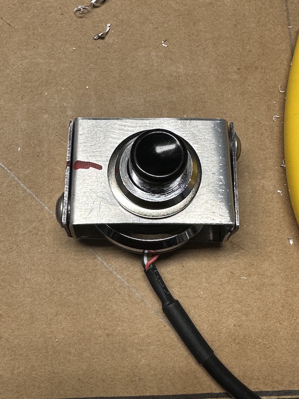
The old school button for the Digital Guard Dawg keyless starter is an interesting touch. Hopefully you have the DGD indicator light somewhere where you can see it. The system is very sequence dependent and if you don't have the light it's going to be challenging knowing where you're at. Lets you know when it's on or off (armed) and flashes when it's ready to start. I had a no start situation last month (no lights...) which turned out to be as simple as the battery in the remote. But in the heat of battle didn't pick right up on that since I had changed the batteries over the winter.
Build 1: Mk3 Roadster #5125. Sold 11/08/2014.
Build 2: Mk4 Roadster #7750. Sold 04/10/2017.
Build Thread
Build 3: Mk4 Roadster 20th Anniversary #8674. Sold 09/07/2020.
Build Thread and
Video.
Build 4: Gen 3 Type 65 Coupe #59. Gen 3 Coyote. Legal 03/04/2020.
Build Thread and
Video
Build 5: 35 Hot Rod Truck #138. LS3 and 4L65E auto. Rcvd 01/05/2021. Legal 04/20/2023.
Build Thread. Sold 11/9/2023.
-
Post Thanks / Like - 1 Thanks, 0 Likes
-
09-26-2023, 07:56 AM
#163
Senior Member


Originally Posted by
edwardb

The old school button for the Digital Guard Dawg keyless starter is an interesting touch. Hopefully you have the DGD indicator light somewhere where you can see it. The system is very sequence dependent and if you don't have the light it's going to be challenging knowing where you're at. Lets you know when it's on or off (armed) and flashes when it's ready to start. I had a no start situation last month (no lights...) which turned out to be as simple as the battery in the remote. But in the heat of battle didn't pick right up on that since I had changed the batteries over the winter.
Thanks Paul. The Lucas button pushes the digital guard dog with a 3/8 inch clear acrylic bar. I also have a 1/8" clear acrylic bar that I will drill out the center of the button and inset then polish so the light should be visible that way via a "fiberoptic effect" (how bright is the question, I guess I could get some 1/8" fiberoptic cable and run that down over the light as well). If that doesn't work or isn't bright enough then I will need to figure out which wires to tap for a separate LED light to be mounted on the dash. I've thought of this and you've answered a question I had about it but was going to "wait and see" so haven't drilled the button out just yet.
Last edited by rhk118; 09-26-2023 at 07:59 AM.
-
09-26-2023, 08:03 AM
#164
Senior Member


Originally Posted by
rhk118

Thanks Paul. The Lucas button pushes the digital guard dog with a 3/8 inch clear acrylic bar. I also have a 1/8" clear acrylic bar that I will drill out the center of the button and inset then polish so the light should be visible that way via a "fiberoptic effect" (how bright is the question, I guess I could get some 1/8" fiberoptic cable and run that down over the light as well). If that doesn't work or isn't bright enough then I will need to figure out which wires to tap for a separate LED light to be mounted on the dash. I've thought of this and you've answered a question I had about it but was going to "wait and see" so haven't drilled the button out just yet.
Sounds like you have it covered. 
Build 1: Mk3 Roadster #5125. Sold 11/08/2014.
Build 2: Mk4 Roadster #7750. Sold 04/10/2017.
Build Thread
Build 3: Mk4 Roadster 20th Anniversary #8674. Sold 09/07/2020.
Build Thread and
Video.
Build 4: Gen 3 Type 65 Coupe #59. Gen 3 Coyote. Legal 03/04/2020.
Build Thread and
Video
Build 5: 35 Hot Rod Truck #138. LS3 and 4L65E auto. Rcvd 01/05/2021. Legal 04/20/2023.
Build Thread. Sold 11/9/2023.
-
Post Thanks / Like - 1 Thanks, 0 Likes
-
09-26-2023, 07:10 PM
#165
Senior Member


Originally Posted by
edwardb

Sounds like you have it covered.

If there was a "fingers crossed" emoji I would use that right now!
-
10-07-2023, 06:27 AM
#166
Senior Member

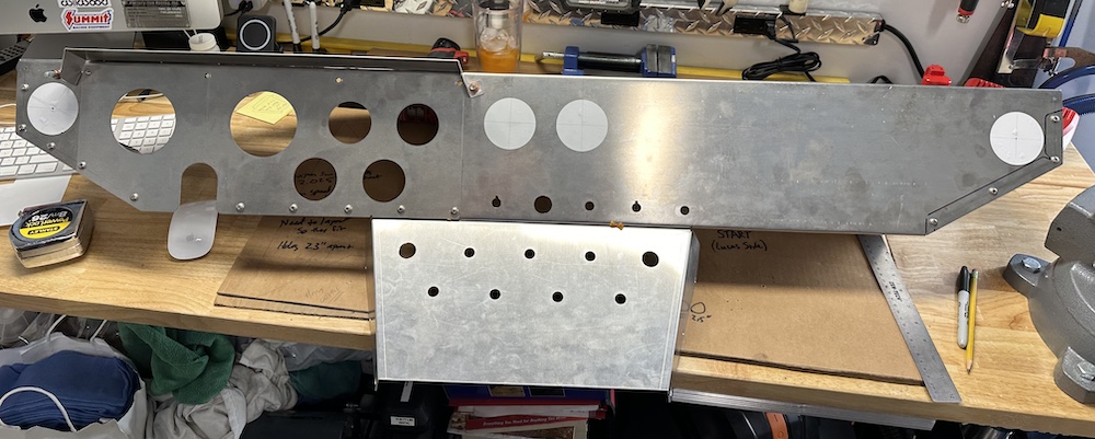
Got my AC vent holes drilled. Using the 2.5 inch vinyl stickers made adjusting placement easy, then served as guides to drill the holes. Used a Milwaukee 2.5 inch hole cutter which worked great, just used light pressure and let the hole cutter do the work. I don't think I need to buy tinsel for my Christmas tree this year after cutting these holes, going to sweep up the aluminum shavings from doing this and sprinkle them over the tree  .
.
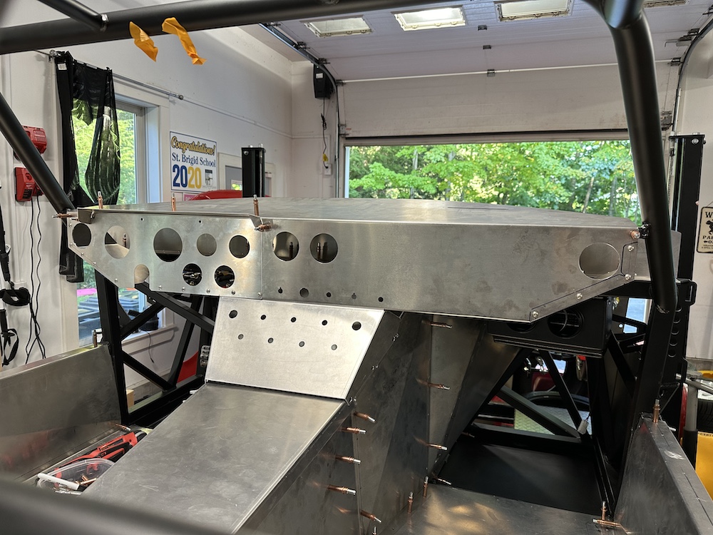
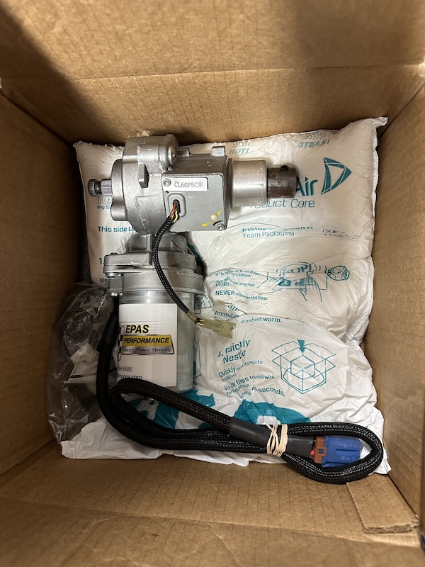
Couple of other updates and possible changes to my build. I was going to use electric power steering, and now that the driver's footbox has the steering, pedal unit, brake lines, and now dash installed it is going to be a very complicated thing to get this to fit where I thought it would fit (it will fit, but I think it will partially hang out from under the dash and that's not OK for me). This doesn't even include the fusebox or vent duct tubing back there yet. An alternative mounting position is in front of the footbox in the engine compartment, but will need engine mounted first to see what space there is to work with. Fortunately my engine isn't built yet so still easy enough to cut bait and go with traditional power steering. The other good thing with the EPAS unit company has steering shaft adapters for a Polaris RZR Side by Side which is what I use to plow with in winter and mine doesn't have power steering, so if it doesn't go in the coupe, I will really appreciate it in the Polaris.
Second development is the seats. I can't get the Corbeau Evolution X's far back enough into the cockpit to be in a comfortable driving position for me. The steering wheel is quite literally in my lap and I can't turn more than 80 degrees or so before I'd have to hand-over-hand turn. Not good enough for a car that will see track time. I've tried the 1 inch and narrower 2 inch Corbeau seat mounts. I've also tried adding the Breeze angled seat mount adapter. I can get them far back enough for my legs to be comfortable. Steering wheel still way too close. I was able to shorten the Russ Thompson Steering column about half an inch as well to get setting out a bit and still elbows aren't even close to 90 degrees. The Evolution X's fit me well though, I do like them.
Folks at Corbeau are amazing and easy to work with. I wish more companies had customer service like they do. I felt that if I could just recline the seat back slightly then my arms would be far enough back and talked to Corbeau. They sent me a warranty-returned reclining RRX seat that they had on hand with a very similar footprint to the Evolution X to test fit and it still didn't get back far enough. Interestingly the lever to recline the seat did not interfere with fitment without the cover on the lever. They also mentioned that they know Corbeau A4s will fit and recline in the Daytona coupe (I'd just have to buy them new, try them and either keep or return). The RRX bolster was too tight for my legs, I think the A4s will have the same problem looking at the seat base.
I put in the basic vinyl Cobra kit seats in there and man they are perfect for me - Can get them back to the wall and there I'm completely comfortable, add the Breeze reclining mount and they're just a little better....hmmm....in any event this is still in process and the real issue is Goldilocks behind the keyboard here just needs to lose a few pounds and I'd probably be just fine  ...have a good weekend all.
Last edited by rhk118; 10-07-2023 at 06:55 AM.
-
Post Thanks / Like - 0 Thanks, 1 Likes
-
10-24-2023, 07:09 PM
#167
Senior Member

She's a Roller! Finally got around to a very basic alignment (eyeballs and measurements from the Manual) and the "LEGO" wheels are on. For the first time in 1.5 years it is sitting on its own, really cool to see it like this. Engine is also all tuned and done. Next phase will be putting the drivetrain together and mocking it up. Then wiring.
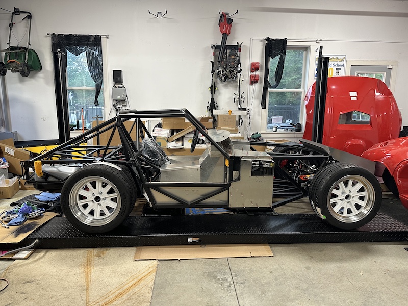
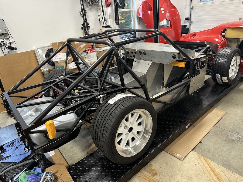
This angle just looked cool, so here you go:
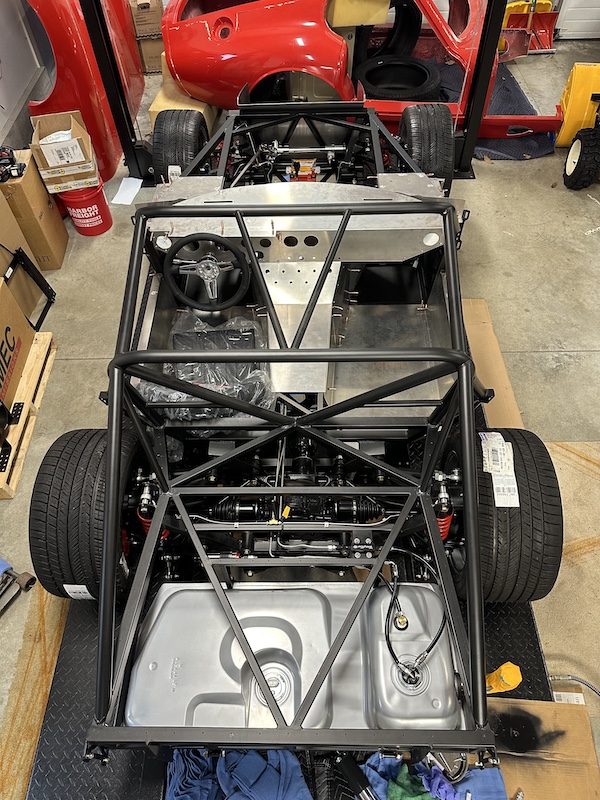
Rear tire:
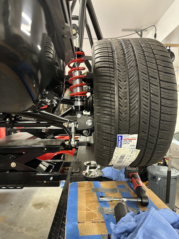
Swaybar attachment:
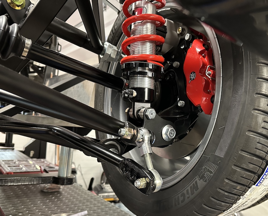
Want to point out the rear swaybar attachment. I've heard 1 of 2 things about the swaybar in the back of these and appreciate any feedback anyone has...even if you just drop a good dad joke I can use on my kids I'll take it  .
.
The first is that the car drives fine with them on front and rear. The second is that the swaybars if used front and back will produce oversteer, and in some cases random snap oversteer (which is not something I would appreciate). Therefore run slightly stiffer springs out back and remove the rear swaybar, but keep the front swaybar. I've heard enough of the folks who track their cars on here say it that I will likely just take off the rear bar for the track. But some part of my OCD is thinking leave it on because 1) it was designed this way and likely does help, 2) parts are good, and 3) it looks cool. When building I bought a longer rod-end than came with the kit so I could link to the last hole on the thing, giving it more flexibility and perhaps SOME swaybar effect but not enough to produce snap oversteer (or so thinks my man-brain). The kit rod ends would not reach the last hole on my bar hence the longer one. Geometry doesn't look great to me with the angle it creates relative to the bar end but when I put the car down it seems OK. With the car up in the air (all wheels in the air), I jacked up 1 tire in the back.The shock does its thing and compresses but then the car starts jacking up and I'm seeing NO rotation of the swaybar affecting the other side. The front end does. Shock works, then there is some rotation of the bar and the other side moves as well slightly in the front. With compression in the back, shock compresses then just comes to a hard stop in the back (shock only 1/3-1/2 compressed, not at its stop)....just wondering if the thing is too stiff and the shock is compressing but then the bar compliance is way too stiff and boom, oversteer? I moved mine to the inner holes in back and still that rear swaybar isn't moving. Obviously this is static by just jacking up 1 wheel and seeing what happens to the other side....nowhere the forces the rear end would see on a track....but interesting. Appreciate anyone's comments or insights here, just random ponderings that are tucked in the back of my head for now, but onward. Today was a really good day, on tires on the ground is a milestone for sure. Love how squat and wide these are!
Oh 1.5 inch spacers all around. Will get the final wheel spacing set once the body is on.
Last edited by rhk118; 10-25-2023 at 06:36 AM.
-
10-24-2023, 11:06 PM
#168
Senior Member

Looks great! Congratulations on the milestone
-
Post Thanks / Like - 1 Thanks, 0 Likes
-
10-25-2023, 08:48 AM
#169
Looking good Hank! I have both front and rear swaybars. Have not seen an issue with street driving. Have not tracked the car yet.
-
10-29-2023, 07:24 PM
#170
My simpleton understanding is that if the rear end is sliding, add a sway bar to the front, and visa versa. I only have a sway bar in the front. That the weight distribution is ~ 45/55, front/rear maybe supports this. What we all could use is a nice skid pad:-) I have not lost traction at either end yet, which i guess speaks more to how I am babying the car so far ;-)
Nice looking work Hank!
Well ... "Babying" is maybe not the best description - Hah! I might suggest opting for the front bar and deciding if the rear bar is needed. I say this as the ride is quite stiff anyway. Sway bars += stiffness.
Last edited by LateApex; 10-29-2023 at 07:34 PM.
-
Post Thanks / Like - 1 Thanks, 0 Likes
-
10-29-2023, 08:47 PM
#171

Originally Posted by
LateApex

What we all could use is a nice skid pad:-) I have not lost traction at either end yet, which i guess speaks more to how I am babying the car so far ;-)
Did someone say skidpad?
https://youtu.be/5w-rAc6tIb4?si=67KaSkPIZO6Awj2o
Do I need more rear swaybar (cowbell)?
Dave
Gen III#17
-
Post Thanks / Like - 0 Thanks, 1 Likes
-
10-30-2023, 07:58 AM
#172

Originally Posted by
Dave Tabor

Haha! You are having way to much fun!!
-
Post Thanks / Like - 0 Thanks, 1 Likes
-
10-30-2023, 08:58 AM
#173
Senior Member

Dave, love it! I'm clearly overthinking this process because the build is taking me so long and just want to be out there doing what you're doing. Definitely don't need any swaybar there. The other thing is these are so low and the rear end doesn't have a lot of movement, swaybar likely (clearly from your video) isn't necessary.
-
10-30-2023, 10:03 AM
#174

Originally Posted by
rhk118

Dave, love it! I'm clearly overthinking this process because the build is taking me so long and just want to be out there doing what you're doing. Definitely don't need any swaybar there. The other thing is these are so low and the rear end doesn't have a lot of movement, swaybar likely (clearly from your video) isn't necessary.
That skidpad stuff was with no rear swaybar. That said, I was TRYING to slide the back end.
I did have the rear swaybar hooked up for quite a while previously and I look at it as a tuning aid, helping to balance out the effect of springs, tires, driving style, etc.
When I first got the car on the track it was far from where it is now, with tire, spring, swaybar, and aero changes made since the first time. I'd say 'embrace the journey', drive it and keep fiddling with it.
Dave
Gen III #17
-
Post Thanks / Like - 1 Thanks, 1 Likes
-
12-17-2023, 10:55 AM
#175
Senior Member

-
Post Thanks / Like - 0 Thanks, 2 Likes
-
12-22-2023, 02:48 PM
#176
Hi Hank,
Great job with the electric power steering; it looks like a very neat installation! The cutting and welding looks beautiful - much better than my flux core welding efforts! To me, welding is an art form! Painting too. And I am at the paint-by-number stages with both but enjoy both tremendously.
Your engine looks great. I too am starting to focus on my engine and expecting to have some cutting and welding to do following Shakey's helpful posts. Happy holidays! John
-
Post Thanks / Like - 1 Thanks, 0 Likes
-
12-26-2023, 08:36 AM
#177
Senior Member


Originally Posted by
jgray

Hi Hank,
Great job with the electric power steering; it looks like a very neat installation! The cutting and welding looks beautiful - much better than my flux core welding efforts! To me, welding is an art form! Painting too. And I am at the paint-by-number stages with both but enjoy both tremendously.
Your engine looks great. I too am starting to focus on my engine and expecting to have some cutting and welding to do following Shakey's helpful posts. Happy holidays! John
Thanks John! Hope yours is going well and I’ve been very impressed that you grabbed the bull by the horns and are learning welding. Obviously I can’t take any credit for the welding, just got to passively watch (cheerleader if you will), and my friend has a LOT of experience welding, as you can see. Can’t take credit for the engine either, just found the motor and pulled it apart and got the block cleaned up then an engine builder took over . However I was involved in the entire process and learned a ton. This is the first real mechanical, real car thing I’ve done in my life other than installing some car stereos and may be a brake job on my wife’s Miata a few years back.
I mean to say all of this in that if anyone is reading and considering whether or not they can tackle a project like this, sounds cliche but if I can do it, anyone can do it. The community is so helpful, and if you need local help there are plenty of car guys who get excited just to be around it!
As you can see with the electric steering I lose any “collapsibility” of the steering column in an accident between the steering wheel and the EPAS unit. Not sure the original setup had much of that either between the wheel and the brace for the steering shaft. There will still be some sliding D shaft installed between the EPAS unit and the steering rack so there is some safety margin if ever an accident and the foot box bends. I also figure that the aluminum splines on the factory five steering wheel will bend a bit without affecting human arms, or just do the open wheel thing if an accident and let go/hold onto the shoulder straps as hard as possible. Maybe a bit heavy of a topic after Xmas but certainly my thought on the path I’m taking with the build. The EPAS really surprised me in terms of how well it fits in there.
The engine is also at my buddies shop and he will help get it taped up for painting, then we will mate it the T-56 and test fit in the chassis. Sounds like the driveshaft from FFR won’t fit with a T-56 and a 302 block, and maybe it will. If not then will measure for a custom driveshaft and get one built if necessary. So my car is sitting in his shop. This part is something early on I decided I needed real help with and it’s been fun to work on it there with him. Once the engine has been test fitted then back she comes for wiring while remainder of panels get powder coated. Hoping by summer next year will be fitting the body.
Happy Holidays and New Year all!
Last edited by rhk118; 12-26-2023 at 08:43 AM.
-
12-26-2023, 11:23 AM
#178
Hi Hank
How solidly the EPA unit goes in is impressive. It makes me believe it will work well because it is so solidly installed; electric motors produce a lot of torque so having it so solidly mounted would seem important.
I too have help with my engine and, like you would not think to tackle this part of the build without help. The cost of mistakes is way too high. But I am going to be trying to figure out and even mockup the whole back of the engine with the flywheel, clutch, pressure plate and transmission. I am thinking of doing this so that I know I have all the necessary hardware (bolts, dowels) when my buddy comes over. I know you got a lot of stuff from Mike Forte like I have. Have you bought additional hardware. I was watching YouTubes last night and see there are bolts for the flywheel to the crank, which I have. And then there are bolts to attach pressure plate, bolts to attach transmission to bell housing, bolts to attach the bell housing to motor. I don’t remember seeing all these in what Mike sent.
I don’t have a driveshaft and will need to get one made. I was looking at diagrams to understand the 2 degree angle thing that I have heard about. I now understand it, but making it happen and measuring is another thing!
I am also going to put the motor mounts on the engine - not sure if I have these. I can see spending a lot on ARP stuff!
-
12-26-2023, 11:39 AM
#179
Senior Member


Originally Posted by
jgray

Hi Hank
How solidly the EPA unit goes in is impressive. It makes me believe it will work well because it is so solidly installed; electric motors produce a lot of torque so having it so solidly mounted would seem important.
I too have help with my engine and, like you would not think to tackle this part of the build without help. The cost of mistakes is way too high. But I am going to be trying to figure out and even mockup the whole back of the engine with the flywheel, clutch, pressure plate and transmission. I am thinking of doing this so that I know I have all the necessary hardware (bolts, dowels) when my buddy comes over. I know you got a lot of stuff from Mike Forte like I have. Have you bought additional hardware. I was watching YouTubes last night and see there are bolts for the flywheel to the crank, which I have. And then there are bolts to attach pressure plate, bolts to attach transmission to bell housing, bolts to attach the bell housing to motor. I don’t remember seeing all these in what Mike sent.
I don’t have a driveshaft and will need to get one made. I was looking at diagrams to understand the 2 degree angle thing that I have heard about. I now understand it, but making it happen and measuring is another thing!
I am also going to put the motor mounts on the engine - not sure if I have these. I can see spending a lot on ARP stuff!
I do know my engine mounts were in a big Energy Suspension Box!
-
12-26-2023, 12:08 PM
#180
Yeah, I’m going to take that box out and look at it. I expect there is hardware for the mount to the frame but not for the mount to the engine.
Last edited by jgray; 12-26-2023 at 08:49 PM.
-
12-31-2023, 09:44 PM
#181
Senior Member

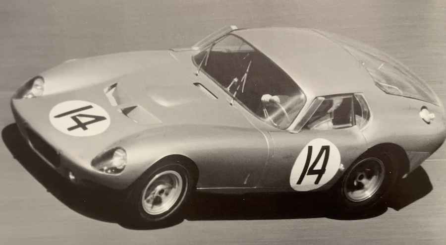
Happy New Year All! Photo of one of the original Coupes at Daytona (or THE original coupe at Daytona). I find it interesting that it has NO mirrors....no looking back, just forward to building in the new year! Haha! Ahhh OK, my cheesy sense of humor won't be changing anytime soon. Thanks for putting up with me. 
Last edited by rhk118; 01-01-2024 at 11:36 AM.
-
Post Thanks / Like - 0 Thanks, 1 Likes
-
01-01-2024, 10:03 AM
#182
Happy New Year Hank and everyone else!
Great picture!
This year should be a lot of fun with our builds going on!
-
Post Thanks / Like - 0 Thanks, 1 Likes
-
01-05-2024, 03:11 PM
#183
Senior Member

-
01-05-2024, 03:43 PM
#184

Originally Posted by
rhk118

Wow - very impressive. The steering wheel/column/power-steering all look great.
And it looks like you are a budding Adrian Newey - next we will see you mocking that up in a simulated wind tunnel! Love it!! And no offense taken!
-
Post Thanks / Like - 0 Thanks, 1 Likes
-
01-20-2024, 10:13 AM
#185
Senior Member

Random Things, #1
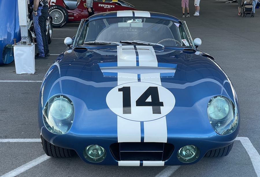
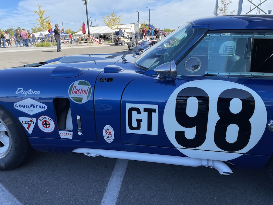
Just a couple of random things in case it helps anyone planning a build. There is another thread that touched on rearview mirrors. I am planning on using Raydyot side mirrors with convex lenses, spun aluminum. I know vision won’t be great compared to the Brock-style mirrors so will see what the blind spot is like once the body is mounted. I just like the look of them on the car. I suspect they are barely more functional than no mirrors at all. I also like their look over the FFR-supplied bullet-style mirror, but obviously this is just me. I’m trying to match the style of the original cars in my build as much as possible.
Raydyot Style, brushed aluminum:
FFR Style polished bullet:
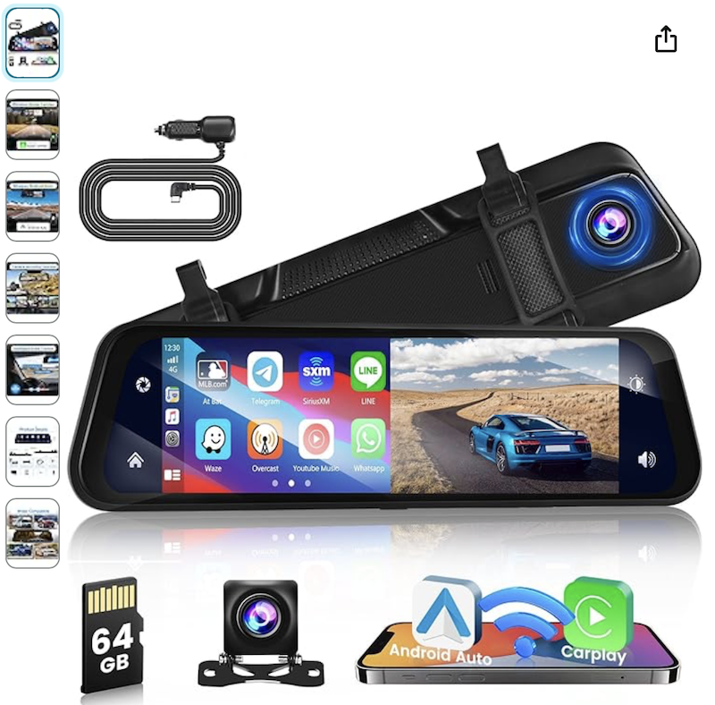
Rearview mirror:
Because I’m concerned about the blind spots in this car, and given my neck injury where I don’t have full right rotation of my head to really check the blindspots (and being strapped in addition to this), I’m going with an always-on rearview camera system. $82 on amazon and there are many with different features. This one has backup camera and Apple Carplay/Android Auto in the event I want to have a small map to assist with navigation and can also show the camera view. Camera supposedly has 180-degree view, and I just need to see cars coming up on me into the blind spot. My concern is this is an interesting car so others might speed up on me to see “what that car up there is” then slow down in the blind spot while “checking the car out”…I just assume this because being a car guy, I’m guilty of this behavior myself, then complete my pass with a thumbs up to the driver. I did look into camera systems using 3 cameras – 2 blind spot cameras and a rearview, but their screens are big, and I don’t want any visible screens….I’ll compromise on the mirror being a screen but that’s it. With the screen off its reflective enough to be used as a regular rearview mirror but obviously not as good as an actual rearview mirror.
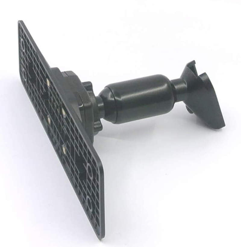
Most of these sell with attached rubber straps to wrap around your existing mirror for a quick install, but I found a mount that you can remove the straps and it screws onto the mirror and mounts to the windshield using a normal windshield mount. So if I hate it, can just switch it out for a regular mirror. I’m going to try and mount the camera inside the car on the rear rollbar center and hopefully the glass doesn’t distort the image too much. If so then will need to get mounted out back somewhere.
Rear Lights:
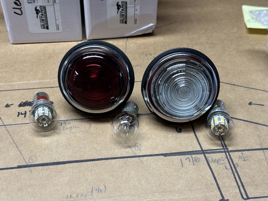
Instead of the factory Five supplied rear backup lights I’m going with glass L488 marker light replicas and replaced the bulbs with red and white LED bulbs from superbrightleds.com which are very bright when tested. The marker lights came from "Finnish" Line Accessories (apparently a Scandinavian company) and come in white, red, and amber (no issues with multiple orders from them, ever). Hopefully these will hold up but I will hold onto the kit rear lights forever just in case they don’t! In order to get the blinker setup to work and also enable push-to-pass functionality with the Russ Thompson steering column I went with a pre-wired setup from 520 Speedworks as relay systems confuse me and this is plug and play (or solder and play). Greg is great to deal with there.
Driving lights:
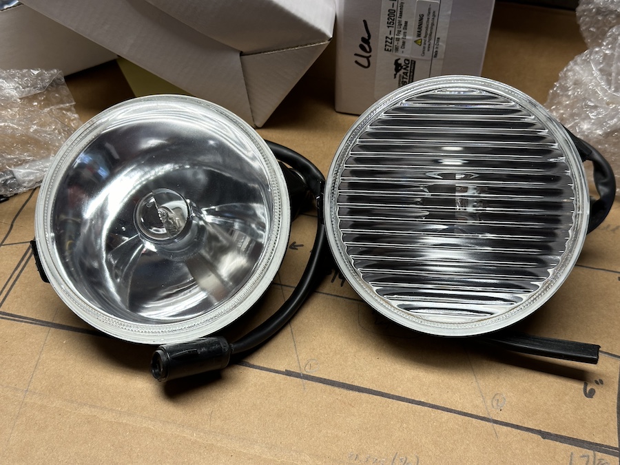
My criteria for driving lights was to fill those 5” openings in front as much as possible. More cosmetic than functional for this one. Digging through the forums I found that years ago John Dol discovered 1993 Mustang GT driving lights fit the space nicely and posted about it - thanks John! (CJ Pony Parts has them). They come in clear or ribbed glass. I did order H3 LED replacement bulbs but it seems none will fit that I can find, they are either too tall in the front and crash into the bulb cover in the reflective housing OR their end is too tall out back, these driving lights are very low profile, so I’m going with what I know and going to put Silverstar H3 halogen bulbs in. These will be the only non-led lights on the car.
Headlights:
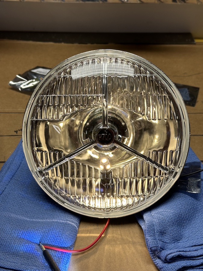
Going with Lucas replicas using LED replacement H4 lights, and they have an extra “blinker” light inside that can have an amber bulb or a regular bulb to be used as blinkers or as daytime running lights. I found LEDs that fit in both amber/orange that would work as blinkers, or just white light, and I like the look of the white light so will use those separately switched. These are labeled "P700" instead of the Lucas symbol, but recently found replicas of the Lucas-style online with the actual Lucas branding. P700 is fine with me!
Last edited by rhk118; 01-20-2024 at 10:29 AM.
-
Post Thanks / Like - 0 Thanks, 1 Likes
-
01-20-2024, 12:07 PM
#186
Senior Member

Transmission and other Shift
So I will be using a T-56 transmission.
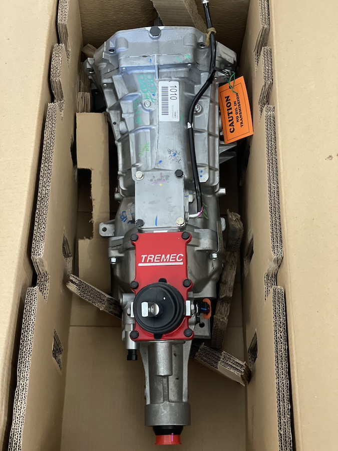
Bought it in 2/2022 when I ordered the kit as there were global pandemic backlogs on everything and I didn’t know when I would get it. It came in pretty quickly (2 months after ordering the kit). So here we are in January 2024 and I am just getting around to test-mounting it. If you get a Tremec transmission with an adjustable shifter, CHECK IT when you get it. Turns out T-56s are notorious leakers which I didn’t know, I just thought of it as an awesome 6 speed with great feel (which it likely still is).
It has a reverse-lockout solenoid and I think Edwardb (Paul) has the easiest solution to activate this solenoid when the car starts moving so you don’t accidentally put it in reverse. I am trying something different that wasn’t available back then: T56 Magnum wiring harness with bluetooth speedometer and lockout control.
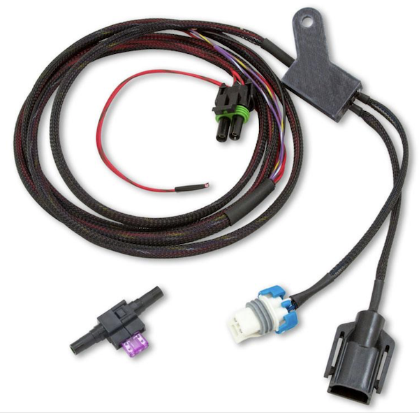
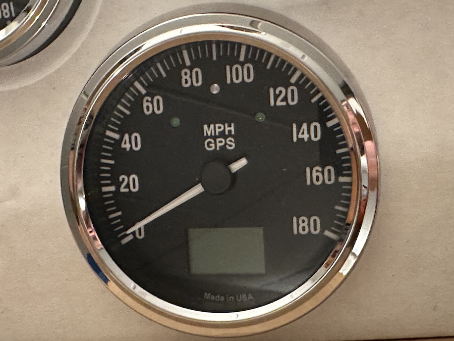
Basically it plugs into the T-56 harness and has a Bluetooth module that lets you pick the speed at which the lockout solenoid activates, but also has a VSS speed sending unit that will send speed information directly from the transmission sensor to a VSS-compatible speedometer. The Bluetooth unit also lets you calibrate the speed signal so the speedo is showing accurate speed. I’m likely oversimplifying things. I have the Speedhut GPS speed gauge so did a little research and Speedhut will take your GPS speedometer and convert it to a VSS speedometer at no charge other than a $15 return shipping fee. So I did that, wanting “analog” speed in the car and no GPS searching for satellites. Interesting thing I also learned is speedhut no longer makes gauges with this font on it anymore, and because of that no counterclockwise speed gauge is available unless I want a gauge with a different font than all my other gauges, no thanks. But they will use your gauge face you give them. Overall process was very easy and can’t say enough about Speedhut, truly pleasantly surprised.
Now for the fun part – test fitting the transmission:
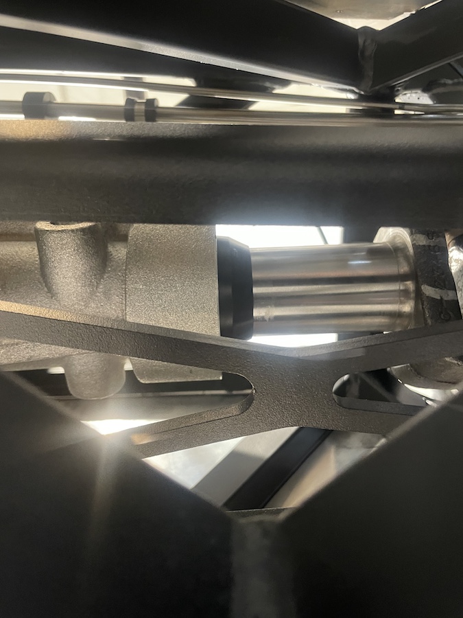
So I learned 2 things from test fitting things in the car. The first is as expected the kit-supplied FFR driveshaft for a 302/T-56 does not fit. About 2.5 inches too short (maybe ½ - 3/4 inch overlap). I suspected this would happen because when ordering the kit I was given one part number, then went to FFR when I placed the order to pay and was told the website was using the wrong part number for the driveshaft for my setup when reviewing my build. So they changed the part number to the correct part number. When the kit arrived the driveshaft which came was the old part number that had been changed and was the wrong part (turns out maybe it was the right part after all). So I talked to FFR and was able to exchange the supposedly wrong part for the supposedly correct part.
I was hoping the posts discussing 302/T56 not fitting in the coupe wouldn’t apply in my case, and turns out mine likely won’t fit. Will need to modify the mounting bracket and/or get a different driveshaft from FFR or have a custom one built. I don’t blame FFR one bit. This was during the post-pandemic parts and labor shortage hell we all lived through and their logistics with these kits and parts is impressive. Plus they’ve always been great whenever I’ve had a parts issue. Just a warning to those looking at using the T-56 on any non-Coyote engine it seems you will have some modifications to the tranny mount and/or driveshaft to perform. Once final measurements are done I will talk to FFR and see if maybe they have a longer driveshaft that will plug and play in my case and spare the customization in that department.  Honestly might be cheaper for me to just buy a different transmission than getting a custom driveshaft and modified transmission mount built.
The other thing that test fitting revealed is I can flip the shifter mount on the T-56 around and it will fit without hitting the crossbar. The coup-de-grace here is when I removed the Tremec shift plate to rotate it 180 degrees, I found a large tear in the inner shifter seal. There is a shifter boot on the outside that is fine, but there is also an inner seal and honestly glad I found it now. But also quite a bit aggravating because you can buy the shifter boot for $15. But you can’t buy the inner seal, you have to buy the entire assembly to the tune of $350+. 
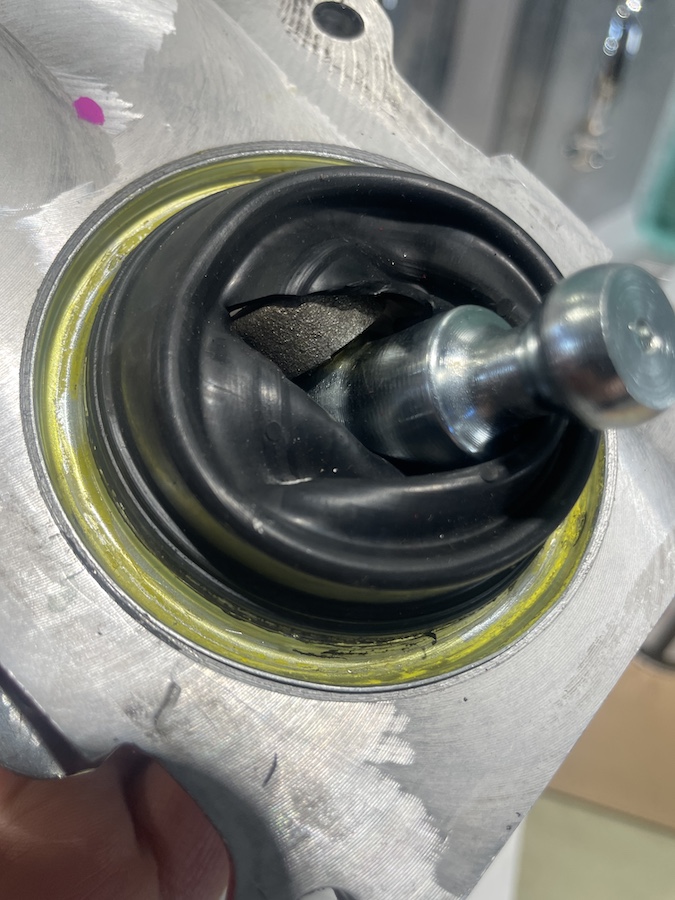
This then led me down an internet rabbit hole reading about these seals and come to find that T-56 are notorious fluid-leakers (or were about 10 years ago), typically from the shift boot and poorly designed inner seal…hopefully this is earlier models, but doesn’t seem that way. If you have a good rear seal on your T-56 consider yourself lucky. Hopefully your vent is a good one and works properly, test it. If those are OK then you only have to worry about the shift boot leaking. If either of those aren't OK then you need to worry about them AND your shift boot leaking.
My summary after reading hundreds of Forum posts about T-56's (read at your own peril): If the inner shifter boot tears you will get leaks around it, just a matter of a couple hundred miles once torn. If the shifter is in the rear position you are likely safe from leaks, even if there is a small inner seal tear because the fluid doesn’t splash as much toward the rear shift position. If your shifter is in the middle (ie turned 180 degrees) or forward position then you will get leaks -- likely small leaks around the shift boot at some point even if the inner seal is OK due to fluid directly spashing up on the seal…to the point that some recommend building a custom baffle to install in this area inside the transmission to lessen the amount of fluid that splashes directly onto the inner seal. If the inner seal breaks in the mid or front position, definite leaks. There are any number of companies that make short throw shifters with plates and better seals that can be installed but many of these will still eventually leak in the mid or front position, but usually not in the rear position. I will likely go with one of these rather than buying a new Tremec part that sounds doomed to eventually leak…if anyone has tried any of these, or knows where to individually purchase a T-56 inner shifter seal I’d appreciate input. UPDATE: Mike Forte was able to source me a replacement take-off part, Thanks Mike!
This also means that I will make my transmission tunnel cover plate removable for future accessibility to the transmission top. Anyhow, really not pleased about this tear – should have checked it the day the transmission arrived, as now out of warranty.
Onward and upward as they say!
Last edited by rhk118; 01-22-2024 at 05:02 PM.
-
Post Thanks / Like - 0 Thanks, 2 Likes
-
01-20-2024, 08:43 PM
#187
I ended up buying Forte's mid shift kit for my TKX. Though I have not used it yet. Seems well built and easy to work on if need be. Also, Mike is super helpful and easy to work with.
Let me know how the rearview mirror works out. I am planning on mounting my camera in the same location.
Brent
Last edited by burchfieldb; 01-20-2024 at 08:52 PM.
-
Post Thanks / Like - 1 Thanks, 0 Likes
-
01-21-2024, 02:09 PM
#188
Senior Member

Beginning Electrical
Work has been pretty busy so have been chewing on how to wire this thing. I know there's the manual. And I've gone through as many threads and videos as possible so thanks to everyone for their pictures, videos, and youtube channels. I will do the same in my documenting, because I'm sure I will do things slightly differently with my wiring. I'm thinking of the power system as a "heart" consisting of the main power from the battery and alternator and how those electrons make their way back to the battery via grounds. What size wire? How many grounds? Chassis grounding only (seems to work)? Or run everything back to the battery ground via wires only? Hybrid of the 2?....Mine will be a hybrid of the 2. The rest of the electronics are the arms and legs and need smaller channels, but good flow back to the battery. Haven't thought much past this. I've had a lot of discussion with JohnG about this as he has been working on his wiring for the past 6 months and thankfully has done a lot of the early work researching this and shared with me. Thank you John. I might understand a relay sometime this century haha  ....ok probably not...
Most interesting to me is the idea he found of having a "clean bus" for power as well as a "dirty bus". The dirty bus supplies power to the big things that can produce big voltage spikes in the system. Starter, alternator, fuel pump, Fans, AC...etc. The "clean bus" is I guess a sort of quiet sanctuary for electrons relatively isolated from those spikes for the more finicky (and turns out expensive) things like electronics and control modules - gauges, ECU, digital guard dawg ignition system...etc. so they presumably don't get fried by an errant spike in electricity. My understanding is the most pure version of this "clean" vs "dirty" power is running 2 separate circuits like siamese twins....they share the same battery but have 2 separate circulatory systems - a dirty power loop with its own power line and ground and a clean power loop with its own separate power line and ground...but that would be a lot of wiring and since this isn't an F1 car where any small failure can take you out, likely unnecessary. So I suspect running a hybrid system allowing the "dirty things" access to a chassis and possibly a direct battery ground, while protecting the more finicky electronics behind relays will mitigate against problems. These are just my early thoughts, and honestly its probably overkill because I've been through countless build threads of both coupes and roadsters and nobody seems to have an electronics problem as I've described just grounding to the chassis, and running power through distribution blocks. So maybe this matters and maybe it doesn't. I am truly new to this. I did build some car stereos in my time and they used their own separate circuits to the main battery as well as to their own dedicated capacitors and batteries because no-one likes alternator hiss, or one speaker out of phase due to parallel line inductance....so wiring at least isn't new to me. Running a relay and understanding positive switching vs ground switching vs both and performing surgery on a wiring harness is new to me.
On that note I can already tell the Power Probe III that edwardb recommended will be a critical tool for me in making sure everything works, and that the electricity is going to where it needs to be going.
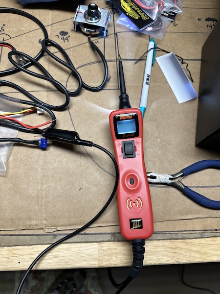
My first wiring feat was figuring out which wires in the Digital Guard Dawg ignition system I'm using power the LED light in the switch. I posted this earlier in my thread but my electronic ignition system push-start button will be buried in my dash and actuated by a Lucas-style push start button. Paul pointed out that I need to be able to see that button in case of errors, not so much to use it on the day to day. So I used the power probe and figured out pretty quickly from the wiring harness which wires power that LED light, and now I can tap into that harness and run a LED light up to the dash so I know what's going on. This alone proved the usefulness of the power-probe to me (also being able to test things before installing). LED's I'm going to use are 8mm polished from Watson's Streetworks. Here you can see one of the LED lights tapped into the Digital Guard Dawg switch and both lights on.
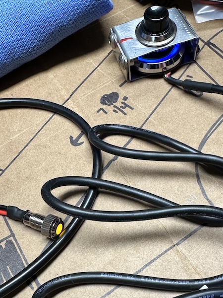
Finally in addition to wiring is where to put everything. I have a lot and due to the electronic steering taking up valuable real-estate near the steering wheel likely won't have room for a glovebox.
The "Brains" I need to hide:
1. Electronic steering ECU
2. Electric parking brake ECU
3. Terminator X ECU and screen
4. Russ Thompson "Blinker and Push-to pass" brain from 520 speedworks
5. Digital Guard Dawg
Add to that any number of extra relays, a couple distribution boxes and likely an extra fusebox (I like the Bussman Relay/Fusebox/distribution box GT_Rich used, seems to get several stones with 1 bird....or something like that). Some things need continuous power and good grounds, Some need to go on accessory power...etc. and I think I just need to sit down and map it all out. Anyhow just typing out loud here. If anything sounds silly, it's probably because it is. The young guys make mistakes because they don't know, the older guys make mistakes because they don't care to check anymore (taps on the altimeter gauge). I guess that makes me young 
Just a word on AI. I believe Apple recently implemented AI for their spell checking and it has gone from bad to worse. Completely changing normally spelled correct words to correctly spelled completely wrong words on me. If there are weird word substitutions, maybe I really am losing my mind...but I'm blaming Apple's bow here! Have a great week 
Last edited by rhk118; 01-21-2024 at 02:32 PM.
-
01-21-2024, 08:58 PM
#189
Check out post 57 on my build thread. GT77 provided some information on an alternative to the Bussman unit that is a lot smaller and completely configurable. He sent me some more information on it, if interested I can send it to you.
-
Post Thanks / Like - 1 Thanks, 0 Likes
-
01-21-2024, 09:44 PM
#190
If you do want to stick with the Eaton Bussman RMTR unit (which to be fair is a really nice unit - just not as a space compact as others but does have nice numbering), I would recommend purchasing the the shorter cover (which I found they started making since the last time I used them in 2016) and might give you more options for mounting. P/N is Eaton Bussman B151-7168-J Best of luck with the build!
-Thomas
-
Post Thanks / Like - 1 Thanks, 0 Likes
-
01-22-2024, 07:55 AM
#191
Senior Member


Originally Posted by
burchfieldb

Check out post 57 on my build thread. GT77 provided some information on an alternative to the Bussman unit that is a lot smaller and completely configurable. He sent me some more information on it, if interested I can send it to you.

Originally Posted by
GT77

If you do want to stick with the Eaton Bussman RMTR unit (which to be fair is a really nice unit - just not as a space compact as others but does have nice numbering), I would recommend purchasing the the shorter cover (which I found they started making since the last time I used them in 2016) and might give you more options for mounting. P/N is Eaton Bussman B151-7168-J Best of luck with the build!
-Thomas
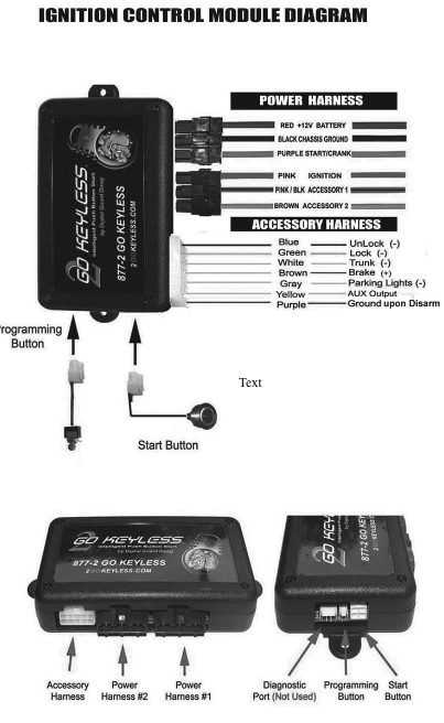
Thanks so much guys, I will check it out. In the meantime I was reading about the Digital Guard Dawg unit (PBS II) I'll be using for electronic ignition and it MIGHT solve my relay problem for the main electrical things. It has 3 60A relays built in - one for the starter and 2 accessories. They can be programmed on or off depending on the ignition state of the unit - Accessory, Start, and Armed - So I likely can feed these relays into the FFR fusebox to the "accessory" and "running" parts of that fusebox. Then I might be able to get away with a couple of individual relays, but this PBS II might have saved me quite a bit of jiggering with wiring. I do want my additional electronics fused in a central location though, don't want to have inline fuses everywhere.
Appreciate you both chiming in!
-
01-22-2024, 09:30 AM
#192
Senior Member


Originally Posted by
rhk118

Thanks so much guys, I will check it out. In the meantime I was reading about the Digital Guard Dawg unit (PBS II) I'll be using for electronic ignition and it MIGHT solve my relay problem for the main electrical things. It has 3 60A relays built in - one for the starter and 2 accessories. They can be programmed on or off depending on the ignition state of the unit - Accessory, Start, and Armed - So I likely can feed these relays into the FFR fusebox to the "accessory" and "running" parts of that fusebox. Then I might be able to get away with a couple of individual relays, but this PBS II might have saved me quite a bit of jiggering with wiring. I do want my additional electronics fused in a central location though, don't want to have inline fuses everywhere.

Appreciate you both chiming in!
Hello Hank. You will need one of the accessory wires out of the DGD PBS II for your RF accessory feed. But the other one is available as you indicated. Per my Coupe build notes, I wired the RF Brown Accessory Feed to DGD Brown Accessory 2. For the other, I wired the DGD Pink/Blk Accessory 1 to a 20 amp breaker and a dual USB accessory socket. If could be used to power something else of course. Just how I chose to use it. Note it does need to be fused or have a breaker. I don't recall why I chose Accessory 1 vs. Accessory 2 for the RF accessory feed. Must have been a reason from when I mocked the wiring up on the bench before installing.
Build 1: Mk3 Roadster #5125. Sold 11/08/2014.
Build 2: Mk4 Roadster #7750. Sold 04/10/2017.
Build Thread
Build 3: Mk4 Roadster 20th Anniversary #8674. Sold 09/07/2020.
Build Thread and
Video.
Build 4: Gen 3 Type 65 Coupe #59. Gen 3 Coyote. Legal 03/04/2020.
Build Thread and
Video
Build 5: 35 Hot Rod Truck #138. LS3 and 4L65E auto. Rcvd 01/05/2021. Legal 04/20/2023.
Build Thread. Sold 11/9/2023.
-
Post Thanks / Like - 1 Thanks, 0 Likes
-
01-22-2024, 11:23 AM
#193
Senior Member


Originally Posted by
edwardb

Hello Hank. You will need one of the accessory wires out of the DGD PBS II for your RF accessory feed. But the other one is available as you indicated. Per my Coupe build notes, I wired the RF Brown Accessory Feed to DGD Brown Accessory 2. For the other, I wired the DGD Pink/Blk Accessory 1 to a 20 amp breaker and a dual USB accessory socket. If could be used to power something else of course. Just how I chose to use it. Note it does need to be fused or have a breaker. I don't recall why I chose Accessory 1 vs. Accessory 2 for the RF accessory feed. Must have been a reason from when I mocked the wiring up on the bench before installing.
Thanks so much Paul. Appreciate you chiming in here. Good to know about putting fuses on the accessory outs, important safety point there as I'm still in "big picture" mode. Reading about this DGD unit it also has MSD filtering to prevent the starter from sending the voltage spikes to everything else, so it actually seems to address a lot of the issues I was rambling on about above!
Last edited by rhk118; 01-22-2024 at 12:04 PM.
-
01-22-2024, 05:08 PM
#194
Senior Member

Transmission shifter seal update
Mike Forte for the win! Was ordering my clutch along with some ARP bolts and he was able to source a take-off shifter and plate for the T-56. Thanks so much Mike!
I wasn't too jazzed about going with a short-shifter for the T56 as its replacement so all is good.
-
01-22-2024, 05:44 PM
#195
Senior Member


Originally Posted by
rhk118

Thanks so much Paul. Appreciate you chiming in here. Good to know about putting fuses on the accessory outs, important safety point there as I'm still in "big picture" mode. Reading about this DGD unit it also has MSD filtering to prevent the starter from sending the voltage spikes to everything else, so it actually seems to address a lot of the issues I was rambling on about above!
Just to make sure there is no misunderstanding -- what you add to the DGD accessory power (USB accessory socket in my case) does need either a fuse or breaker. Whichever DGD accessory power wire you connect to the RF brown accessory wire does not need a fuse or breaker. The RF wire is feeding the panel where all powered circuits are already fused. Hope that makes sense.
Build 1: Mk3 Roadster #5125. Sold 11/08/2014.
Build 2: Mk4 Roadster #7750. Sold 04/10/2017.
Build Thread
Build 3: Mk4 Roadster 20th Anniversary #8674. Sold 09/07/2020.
Build Thread and
Video.
Build 4: Gen 3 Type 65 Coupe #59. Gen 3 Coyote. Legal 03/04/2020.
Build Thread and
Video
Build 5: 35 Hot Rod Truck #138. LS3 and 4L65E auto. Rcvd 01/05/2021. Legal 04/20/2023.
Build Thread. Sold 11/9/2023.
-
Post Thanks / Like - 1 Thanks, 0 Likes
-
01-22-2024, 06:01 PM
#196
Senior Member


Originally Posted by
edwardb

Just to make sure there is no misunderstanding -- what you add to the DGD accessory power (USB accessory socket in my case) does need either a fuse or breaker. Whichever DGD accessory power wire you connect to the RF brown accessory wire does not need a fuse or breaker. The RF wire is feeding the panel where all powered circuits are already fused. Hope that makes sense.
Yes, that makes sense to me Paul. I appreciate your thoughtfulness in picking up on that detail in my reply as it does help, but now I have a question:
Theoretically I would hook up accessory #2 (brown wire) to the RF harness brown wire just because they are the same color and I sometimes need to troubleshoot things from myself which keeps it simple (plus you did it and it works  ), which means my accessory #1 will be open. Because it is a 60A relay, I could then run accessory #1 (the remaining available one) to a power distribution box and run 2-3 things off of that such as a USB adapter, powered mirror, internal footwell lights...etc. and they would each be fused separately? or should I run a 20A breaker between the DGD and that power distribution box AND separately fuse everything that Accessory cable is running? I don't think I would put 20A of draw on that line but I certainly wouldn't try and approach the 60A the DGD is rated for. Sorry if this seems silly.
FYI I bought my father in law a Power Probe for belated X-Mas gift as he's currently rebuilding a Land Rover IIa from the ground up and about to start his wiring. That is one handy device. Thanks for finding it
Last edited by rhk118; 01-22-2024 at 06:07 PM.
-
01-23-2024, 05:49 AM
#197
Senior Member


Originally Posted by
rhk118

Yes, that makes sense to me Paul. I appreciate your thoughtfulness in picking up on that detail in my reply as it does help, but now I have a question:
Theoretically I would hook up accessory #2 (brown wire) to the RF harness brown wire just because they are the same color and I sometimes need to troubleshoot things from myself which keeps it simple (plus you did it and it works

), which means my accessory #1 will be open. Because it is a 60A relay, I could then run accessory #1 (the remaining available one) to a power distribution box and run 2-3 things off of that such as a USB adapter, powered mirror, internal footwell lights...etc. and they would each be fused separately? or should I run a 20A breaker between the DGD and that power distribution box AND separately fuse everything that Accessory cable is running? I don't think I would put 20A of draw on that line but I certainly wouldn't try and approach the 60A the DGD is rated for. Sorry if this seems silly.
FYI I bought my father in law a Power Probe for belated X-Mas gift as he's currently rebuilding a Land Rover IIa from the ground up and about to start his wiring. That is one handy device. Thanks for finding it
You wouldn't need to add a fuse/breaker on the Accessory 1 lead you described if whatever you have attached to it downstream via a power distribution box, bus bar, whatever each have their own protection devices. As long as the total of what you're connecting doesn't exceed the rating of the circuit (60 amps) which it sounds like it doesn't. Technically, protection on the line out of the DGD wouldn't hurt anything. But adds another layer of possible failure that isn't necessary. The Power Probe is a handy device for sure.
Build 1: Mk3 Roadster #5125. Sold 11/08/2014.
Build 2: Mk4 Roadster #7750. Sold 04/10/2017.
Build Thread
Build 3: Mk4 Roadster 20th Anniversary #8674. Sold 09/07/2020.
Build Thread and
Video.
Build 4: Gen 3 Type 65 Coupe #59. Gen 3 Coyote. Legal 03/04/2020.
Build Thread and
Video
Build 5: 35 Hot Rod Truck #138. LS3 and 4L65E auto. Rcvd 01/05/2021. Legal 04/20/2023.
Build Thread. Sold 11/9/2023.
-
Post Thanks / Like - 1 Thanks, 0 Likes
-
02-09-2024, 07:57 PM
#198
Senior Member

-
Post Thanks / Like - 0 Thanks, 1 Likes
-
02-09-2024, 08:20 PM
#199
Senior Member

-
02-09-2024, 08:27 PM
#200
Senior Member

Here are pictures of the transmission mounting plate:
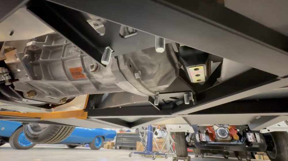



 Thanks:
  Likes:


 Reply With Quote


 .
.  .
. 


 Honestly might be cheaper for me to just buy a different transmission than getting a custom driveshaft and modified transmission mount built.
 ....ok probably not...