-
-
Post Thanks / Like - 0 Thanks, 1 Likes
-
Radiator and condenser install
I now have the radiator and condenser installed in the car. I ended up taking Breeze Shroud and fan off and rotating it 180 degrees so that the angle part of the shroud is at the bottom. I did this because I wanted to push the radiator as vertical as I could get it because the hood hinge hits the lower AC attachment. I became aware of the hinge issue watching the Oak Hollow YouTube channel and then read PaulB's thread and saw he described the same issue. So this was my first experience drilling out rivets, which went well. I put 10-32 button heads, washers, and lock nuts in the enlarged holes which will allow me too take the shroud off if I need to. Shoutout to Yellville and his YouTube channel for his video on AC installation - it help me to see his setup.
Here is a photo of the passenger side hood hinge hitting the AC fitting:
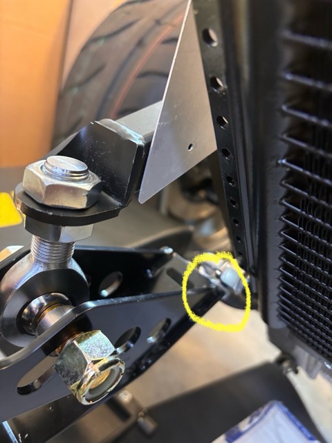
I figure I will have to cut the end of the hinge off and make a new elongated hole.
Also installed the expansion tank. Used some L shape aluminum to create a bracket to mount the lower support - after I did this I came across a flat piece of metal in the box that was meant for this purpose! Well I had fun with my L shaped bracket and installing rivnuts into it.
I glued inner tube rubber to the underside of the radiator mount rather than using the half moon weather stripping described in the manual. And I used contact adhesive and zip ties to connect the split fuel tube to the bottom radiator mounts.
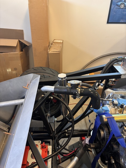
This photo shows the expansion tank and the 90 degree hose that will hopefully connect to a new thermostat housing that has a vertical connection that I'm waiting for delivery on.
I also just received some 5/8 Pex hose clamps which I used on the vent tube coming out of the bottom of the tank; seems to work well - my mechanic buddy prefers these to the standard hose clamps.
Next is installing the drier, and making AC hoses. Unless I get distracted by setting up the carb linkage which is quite the puzzle.
-
Senior Member

Looks great John! I have the same tight fit of my radiator. Agree that the lower radiator connection is VERY tight. Question on the Forte mechanical throttle linkage -- is there any play in the pedal where it goes through the aluminum into the engine compartment....mine definitely has a little bit of play to it and I saw Scott's at the FFR event last year and his has a bit of play when installed as well. Wondering if this is how they are supposed to be or if it is maybe just a few that are that way.
Also where your hinge strikes the AC evaporator fitting - once you have the struts fitted for the hood, theoretically that will be the "stop" that prevents the hinge from rotating that far where it strikes the AC fitting....I guess we will find out!
-
-
I thought I wanted a darker blue for my type 65 but man, that is one gorgeous color on your beast!  having second thoughts!
Can you get me info on where to get those beautiful wheels?
Thanks
-

Originally Posted by
TechT

I thought I wanted a darker blue for my type 65 but man, that is one gorgeous color on your beast!
having second thoughts!
Can you get me info on where to get those beautiful wheels?
Thanks
Hi TechT,
If your talking about the pictures I posted back in post #8 that is not may car, but it is the color and scheme that I want. It is one of the Gen 3 Type 65s that Factory Five built; I saw it in their showroom at the factory back in 2022. If you look at the Type 65 page on their website you will see it. I think the wheels at 19s but I don't know what brand - I expect that they can give you the info.
-
Originally Posted by
jgray
Hi Hank,
I appear to have been able to get rid of the slop in the Forte throttle pedal by adding two washers and tapping into the male part of the throttle pedal splined connector and screwing in a bolt. I did this back in January, and tried to describe it with photos, but now I see the photos are missing and my description is drawn out across several posts. So let me try again!
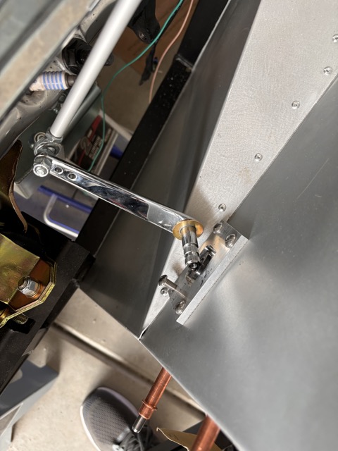
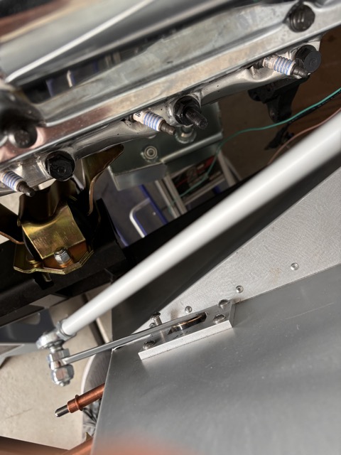
Here are some photos from today. I recently took the throttle pedal assembly apart to angle the part in the engine bay towards the front of the car, pointing at a 10 oclock rather than straight up. I did this to get the throttle linkage arm on the firewall further away from the firewall. The result is the pedal can go through its full range of motion without the arm hitting the firewall. I could have shortened the linkage but then the linkage would be at a more vertical angle which would reduce the rotation of the arm on the firewall. I fully expect to be rejiggering this whole setup again to get the correct of movement at the far end of the throttle linkage where it connects to carb linkage. And then there is the consideration of whether the movement of that end is linear with the movement of the pedal. Lots of places to make adjustments once everything is connected.
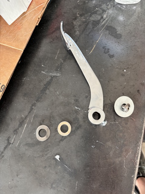
This shot shows the 1/4 -20 bolt and large washer. The bolt goes into the threaded blind hole in the male throttle pedal spline. The washer helps pull the male spline into the female spline. Once it is tight I then tightened the set screw that goes through the female spline. The other washers are a slim washer which came with my Wilwoods, and the spring washer which came with the throttle linkage. Overall my aim was to eliminate the side to side slop, which I appear to have done. I say appear because I wont know for sure until everything is hooked up.
This shot shows the end of the throttle in the engine bay showing the washer that I added on this side and if you zoom in you can see the blind hole that is threaded
Another shot of the engine bay side. The washer is a another thin washer that was an extra from my Wilwoods:
And here is a shot from the footbox and you can see the bolt and the washer. I am swapping the four bolts on the bracket so that the bolt heads are in the footbox and lock nut in the engine bay.
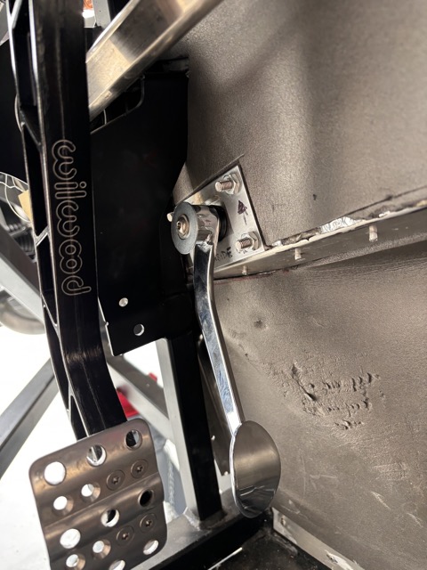
An issue that I have is I cannot put my foot on the gas pedal without hitting the brake, even withe brake pedal pad moved over to the leftmost position. I am figuring I will need special skinny shoes, and not my regular shoes!
I ended up making a custom panel for that one and gained several inches of space.
20230316_155837.jpg20230414_134313.jpg
-
Thanks for the input! Nice solution! I was looking at the panel this morning wondering how hard it would be to drill out the rivets and make a replacement panel. You have me given me cause to take another look. I have test fitted the engine and will be pulling it back out soon; so now is the time. Thanks
-
Originally Posted by
jgray
Thanks for the input! Nice solution! I was looking at the panel this morning wondering how hard it would be to drill out the rivets and make a replacement panel. You have me given me cause to take another look. I have test fitted the engine and will be pulling it back out soon; so now is the time. Thanks
1/8 inch drill bit will make short work of it.


 Thanks:
  Likes:


 Reply With Quote
