-
Manual Fan Override Button
Scouted a few threads on this as I'd like to have a manual button to activate the fan. I'm using the Billet Button switches and not the toggle. Does this diagram look correct and am I missing anything. I thought maybe I needed 85 to tap into the Dark Green Thermo fan wire, but not sure?

-
Senior Member

I did my override through the ground. Ron Francis harness with a standard ground to the temp switch (which is the ground circuit). I cut into the that with toggle switch to separate ground so if I switched it the fan turned on. What you have is way more advance but I don't see why it wouldn't work. I would think you would be sending two sources of 12v DC to the fan at the same time if the fan override is switched on and the fans normal path is on. What I don't know is does that matter. I am guessing no but that is only a guess on my part.

Last edited by Blitzboy54; 09-03-2024 at 11:33 AM.
-
Post Thanks / Like - 1 Thanks, 1 Likes
-
Senior Member

Agree with Blitzboy, my temp switch and manual over-ride are both run via the ground.
F5R #7446: MK4, 302, T5 midshift, 3.55 Posi IRS, 17" Halibrands
Delivered 4/4/11, First start 9/29/12, Licensed 4/24/13, off to PAINT 2/15/14!! Wahoo!
-
Post Thanks / Like - 1 Thanks, 1 Likes
-
Not a waxer

When I do them I just run the manual toggle in parallel with the thermo switch. I also use an indicator light which is on whenever the fan is energized, whether via manual toggle or automatically from the thermo switch.
Jeff
-
Post Thanks / Like - 0 Thanks, 2 Likes
-
Senior Member

Yup, just put a switch in parallel with the thermal switch that already turns the fan on. Just make sure the switch is rated large enough to handle a radiator fan.
Matt
My build thread
here
-
Post Thanks / Like - 1 Thanks, 0 Likes
-
Thanks for the replies. Electrical is not my strong suit. When you guys say 'run parallel with the thermo temp switch', do you mean to tap into the dark green harness wire and use as ground? The billet buttons wire up a little differently than the toggle. Took a bit to figure it all out but they light up when the button is pushed, so I can use that as the indicator light when the fan is on.
Last edited by cv2065; 09-03-2024 at 08:17 PM.
-
Senior Member


Originally Posted by
Jeff Kleiner

When I do them I just run the manual toggle in parallel with the thermo switch. I also use an indicator light which is on whenever the fan is energized, whether via manual toggle or automatically from the thermo switch.
Jeff
Ditto what Jeff said. Toggle switch in parallel with the thermal switch (ground) and an indicator (aircraft press to test indicator) that is on when ever the fan is on. Either fan thermal switch or toggle switch will turn on the fan and the light. The light is mounted next to the temp gauge.
Run the ground wire from #85 to a toggle switch then to ground. Low amps on the x1-x2 thats 85 and 86 on your relay. Dont install a switch in the main fan power source. You can add the indicator light in parallel with #85
Last edited by Rebostar; 09-03-2024 at 05:27 PM.
-
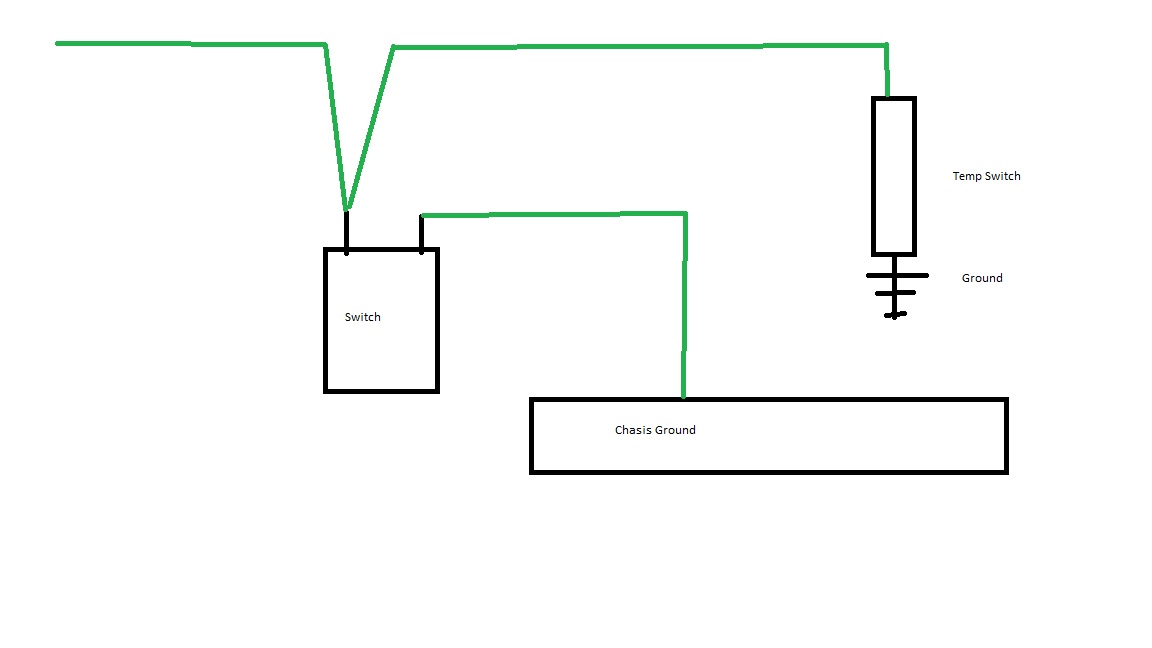
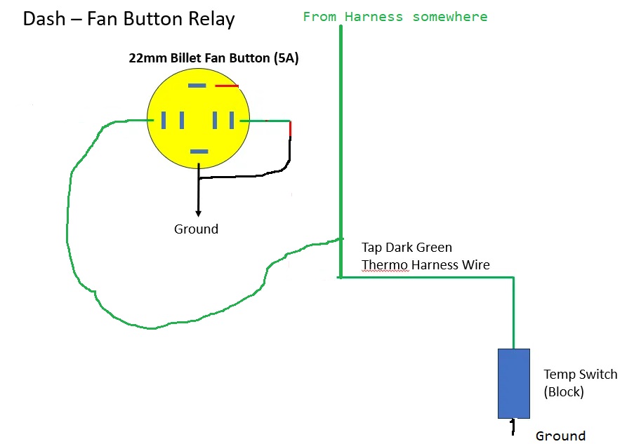
Thanks again for all of the feedback. I altered the diagram to this:

The billet button has an LED, so I'm getting power for that through the IGN/ACC circuit. The button also has a red and green wire that are combined and would typically go to a relay or device like the fan, but I'm tapping into the Dark Green Thermo Harness Wire instead. Then the button has its own ground as well. The billet button is only has a 5A capacity which is why I added the 30A relay in the first place. I'm assuming since this is operating off of the ground, I won't need that? Does this look accurate?
-
Post Thanks / Like - 0 Thanks, 1 Likes
-
Senior Member

From the looks of that wiring diagram, it looks to me like you'd be wiring the new switch in SERIES with the thermal switch, not in parallel. My fan thermal switch is green, and the switch itself is a chassis ground to the engine block. When the switch closes (hot engine) the green wire is now connected to ground and energizes the fan relay. When the fan relay changes state the fan spins. Easy peasy. What you want to do is ran a PARALLEL conductor off that green fan thermal switch wire to one side of your fancy switch, with the other side to ground. That will replicate the performance of the fan thermal switch at your own command.
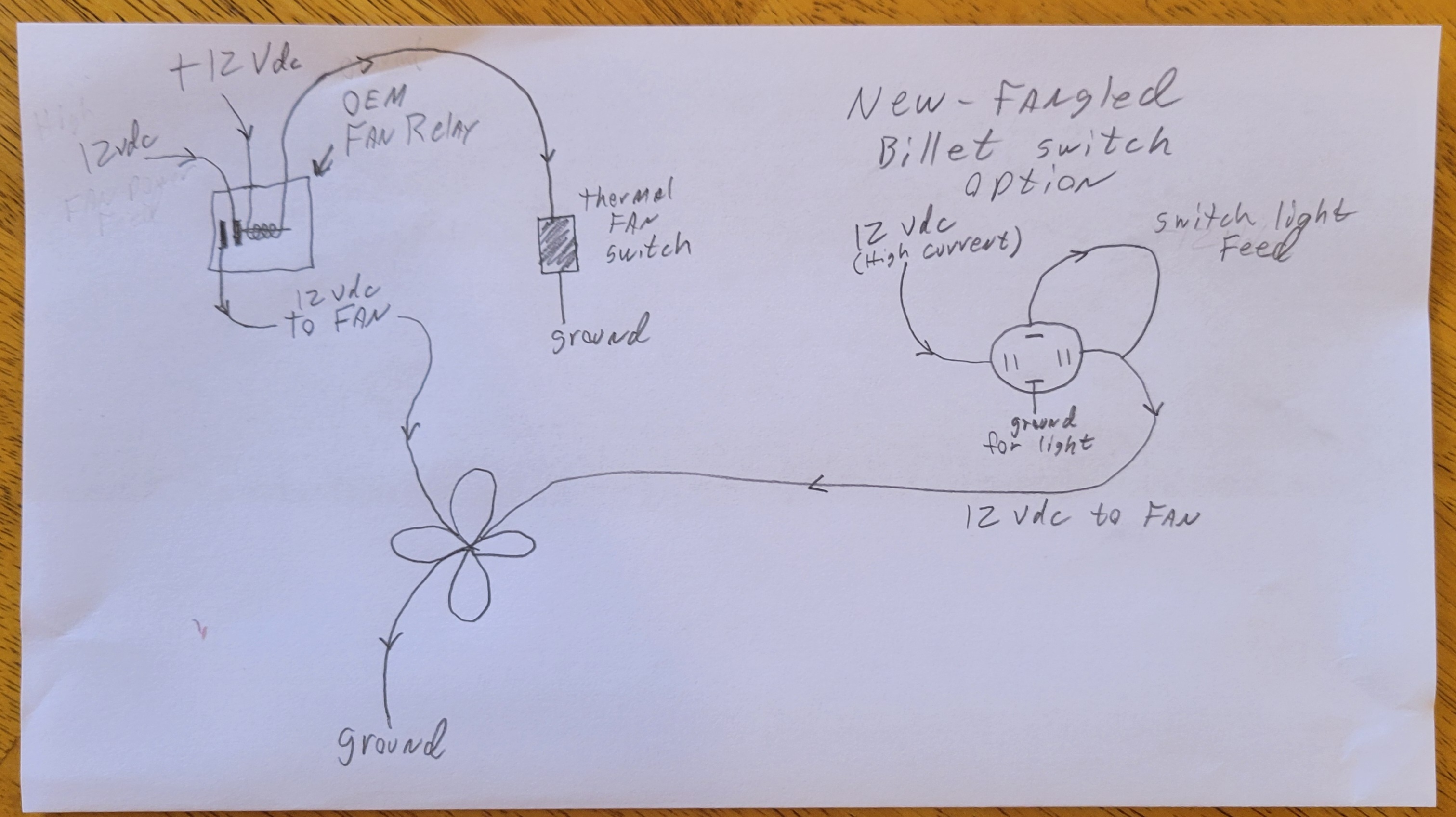
Here's my ghetto wiring diagram:

Without some really fancy wiring, I don't see how you can get the light on the switch to work since the green wire is grounded when the thermal switch closes and what's upstream from it is a load, not a power source.
Edit: I just thought of a solution. You could run a conductor from the fan power feed (that goes directly to the fan) up to the power for the light on the switch. That will make the switch light come on when you've activated the fan. But ALSO come on when the thermal switch turns the fan on as well.
OR, just omit the light feature from the 22mm switch. It is neat though, but without diodes and whatnot I'm not seeing an easy solution.
Last edited by MB750; 09-05-2024 at 07:59 AM.
Matt
My build thread
here
-

Originally Posted by
MB750

OR, just omit the light feature from the 22mm switch. It is neat though, but without diodes and whatnot I'm not seeing an easy solution.
Yes, the 12V off of the IGN/ACC is needed for the LED to work. How does the original diagram with the relay look? I know I would be running directly to fan and not through the thermo harness wire.
-
Senior Member


Originally Posted by
cv2065

Yes, the 12V off of the IGN/ACC is needed for the LED to work. How does the original diagram with the relay look? I know I would be running directly to fan and not through the thermo harness wire.
Your original diagram still assumes there's a +12V source feeding through the relay and into the OEM thermal switch. That's not the case (technically). What's up there is the coil of a relay. There's technically 12 VDC on the other side of that coil, and through the coil into the green wire if you were to meter it with a digital multi meter, but as soon as it's grounded and the circuit is now closed the relay assumes electrical load and the relay changes state (and that wire becomes a ground). It's called a "Switched Ground" and it's pretty common in 12 VDC applications. If you put a switch, relay, or anything in there as you've drawn it, you'll still be waiting for the OEM thermal switch to close before the fan comes on. AND, if you leave your switch open while the OEM thermal switch closes, the fan will NOT come on because your switch will be holding the circuit open.
Edit: One thing I just noticed. That green box on your first drawing that says "FAN". Is that the actual fan, or the thermal fan switch? If it's the fan, than your circuit will work fine but you won't have the automatic operation of the OEM thermal switch.
Last edited by MB750; 09-05-2024 at 09:00 AM.
Matt
My build thread
here
-
Senior Member

Usually the billet switch light can be on all the time or only when the button is switched. In that case, on Matt's drawing, just pull 12v from the left side to the appropriate LED terminal that is switched to ground when button is active. Ckeck the switch instructions. On your last drawing, as Matt said the switch and the temp sensor would be in series and require both to turn the fan on.
-
Senior Member

Go pick you up an electrical meter, the one's at Wally World are more than enough.
Mrk III, 331 stroker, Borla stack injection, T5, 3:55 IRS, Power steering and brakes. Kleiner body & paint
-
Senior Member

I installed the manual switch in my car, but was wondering, If you install a manual switch in parallel with the engine coolant temperature sensor, and you manually turn on the fan at a temperature that is below the PCM/ECU setting for turning on the fan, will this impact the air fuel mixture or timing? On my 4.6L SOHC motor, for example, I think that the stock setting for turning on the fan is around 210 degrees. If I were to turn on the fan at say 180 degrees, will the PCM/ECU adjust the air fuel mixture based upon the PCM/ECU receiving a false 210 degree signal? Does it matter? I actually haven't had an opportunity to use the switch yet; the temperature here in upstate NY has been pretty mild, and my coolant temperature hasn't gone above 190 since I installed the switch.
-

Originally Posted by
MB750

Edit: One thing I just noticed. That green box on your first drawing that says "FAN". Is that the actual fan, or the thermal fan switch? If it's the fan, than your circuit will work fine but you won't have the automatic operation of the OEM thermal switch.
Yes, that is the actual fan. I was thinking to just run the button independent of the thermo switch. That way I think I can just run through the relay as diagrammed and I’ll tap into the main power wire of the fan in the harness. The only question would be around the fan ground. Would the switch still see that ground through the harness connector?
-
Senior Member

EUREKA!!! I think I may have figured out a way for you to have your cake and eat it too.

The OEM fan control system is left alone. It works in a standalone fashion automatically if it needs to.
The new-fangled billet switch needs a high current feed in order to safely feed the fan without blowing fuses. I would recommend actually tapping off the original 12 VDC feed for the fan way up before the fan relay. Then feed the switch LED from the output of the switch so the light comes on when the fan is fed. I also know there's not two inputs to the fan. Just tap into the original wire with a solid, automotive rated splice, and use the same gauge wire.
The reason I think this'll work is because it doesn't matter that the fan is fed from two feeds because any backfeeding to the relay won't matter because the contact is open. And even still, if for some reason both the switch is closed and the relay is closed at the same time, it's all fed from the same 12 VDC source.
Matt
My build thread
here
-
Post Thanks / Like - 0 Thanks, 1 Likes
-
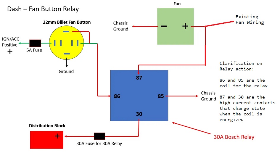
Thanks for the diagram Matt! So in a nutshell, the billet switch is wired similar to what I have in the first diagram (Ground and 12V IGN/ACC), only difference is that the red/green switching wire that I had going to the relay would now splice directly into the hot fan wire in the harness? One question. With the switch only being 5A, wouldn't I have an issue with that switching the fan on and off without the relay?
-
Senior Member

Not exactly. The high current output from the Bosch relay connects to the existing high current wire feeding the fan. Like this:

You COULD just use the Billet switch, but you'd have to confirm it's amperage rating is higher than what the fan draws. Personally, I would go that route just to keep the wiring cleaner, but then you'd have to place another order from Australia. That's what I did for my high-beam switch on my dash. I had a hunch 5A wouldn't be enough for the high beams, so my toggle for the brights is a 16A rated switch from them.
Last edited by MB750; 09-07-2024 at 06:59 AM.
Matt
My build thread
here
-
Senior Member


Originally Posted by
rich grsc

Go pick you up an electrical meter, the one's at Wally World are more than enough.
It is said; Holding a multi-meter in ones hand doesn't make you an electrician, any more than holding a spanner makes you a mechanic. Without throwing shade on anyone on this forum, there are plenty of guys who will put their hand up admitting their fear of all things electrical. I see first hand, plenty of people struggling to understand the concept of something they cannot see. I have taught a hydraulics circuit expert some electrical basics. His biggest struggle was that open circuit means flow in hydraulics, but no-flow in electrical. And vice versa. With schematics laid out on the table and a fluoro highlighter to trace the flow, he did fine. Trying to get him to visualise a circuit was very difficult, but improved with practice.
A multi-meter, is exactly that, a test instrument with multiple functions, to measure resistance, voltage and current as a minimum. Throw that into the mix with schematics, coloured wires, electrical terminologies and it is a gargantuan struggle for even the keenest car guy.
I write this, because as a sparky with 35 years of fault finding experience, I can visualise and provide a solution to most of the electrical questions that come up on this forum. However, I frustrate myself by not being able to put anything much of a useful solution in words. Its just that hard. I commend the guys that draw up sketches, make tests, build working examples, dive in and learn the basics. I can almost see the cogs turning in their minds.
I have learned many new skills building my cobra and absorbing knowledge from this forum. There are so many talented people here. As Rich says, go out and get yourself a multi-meter (Get some accessories too, alligator clips, hook clips). Watch you tube, get a sparky mate to show you around your meter, learn how to use it and most of all, take satisfaction in being a fearless fault-finder.
Cheers,
Nige
Mk.4 FFR supplied Right hand drive
Received 12/2012 completed 12/2019
Gen1 Coyote / TKO600 / IRS
Lots of mods to make compliant for Australian design rules
-
Post Thanks / Like - 1 Thanks, 0 Likes
 MB750
MB750 thanked for this post
-
Senior Member

Seems to me the desire to use that switch vs a plain toggle in the ground side parallel to the temp sensor is creating way, way more complexity than it is worth. Kind of a fun exercise I guess but wow...
FFR MkII, 408W, Tremec TKO 500, 2015 IRS, DA QA1s, Forte front bar, APE hardtop.
-
Not a waxer

-
Senior Member

Some people talk themselves out of a neat idea just because it's too complicated to figure out. No offence to anyone intended, but that's where my brain shines. I love solving problems. Especially electrical and mechanical problems.
Matt
My build thread
here
-

Originally Posted by
MB750

Some people talk themselves out of a neat idea just because it's too complicated to figure out. No offence to anyone intended, but that's where my brain shines. I love solving problems. Especially electrical and mechanical problems.
Agreed Matt. It's the attention to detail on the small things that takes cars to the next level.
The billet switch is rated at 5A. I think the RF fan fuse is rated at 30A and the fan has a max output of ~18A. I was trying to get away from the toggles if possible.
-
Senior Member


Originally Posted by
cv2065

Agreed Matt. It's the attention to detail on the small things that takes cars to the next level.
The billet switch is rated at 5A. I think the RF fan fuse is rated at 30A and the fan has a max output of ~18A. I was trying to get away from the toggles if possible.
Then if that's the case the high current ones won't work either. They're only 16A rated.
Matt
My build thread
here
-
Senior Member

The switch isnít handling the current. Itís simply allowing the relay to close the contacts where the high current will be run through. You want the relay to match the amp rating not the switch, thatís the whole point of it anyways.
EditÖ.sorry might have misunderstood, you were talking about only using a switch. Just do the relay like MB750 drew up, super simple and will handle the current.
Last edited by Kbl7td; 09-09-2024 at 01:38 PM.
-

Originally Posted by
Kbl7td

The switch isn’t handling the current. It’s simply allowing the relay to close the contacts where the high current will be run through. You want the relay to match the amp rating not the switch, that’s the whole point of it anyways.
Edit….sorry might have misunderstood, you were talking about only using a switch. Just do the relay like MB750 drew up, super simple and will handle the current.
So I think we're talking about the diagram in post #18. That's the way that I have it wired right now with a new power lead splicing in from relay to fan.
-
Senior Member


Originally Posted by
cv2065

So I think we're talking about the diagram in post #18. That's the way that I have it wired right now with a new power lead splicing in from relay to fan.
Lemme know when you've tested it. If my idea doesn't work for you, I'll personally head over with my meter and tools to see why not. I'm in Tampa.
Matt
My build thread
here
-

Originally Posted by
MB750

Lemme know when you've tested it. If my idea doesn't work for you, I'll personally head over with my meter and tools to see why not. I'm in Tampa.
Thanks Matt! Will do. I have a MM. just need to learn how to use it. ��


 Thanks:
  Likes:


 Reply With Quote


