-
Senior Member

Front Suspension Setup
Hey guys, doing a quick mockup on the front suspension. It's a pin drive front setup that uses SN95 spindles with adapters for the top ball joint. Because of this there's not a lot of information on it from FFR, Dave L even looked back in some older manuals when it was a standard option and couldn't find anything. So I'm a bit like a blind man at an orgy, I'm just feeling my way around....
As a start, when in ride position are the lower control arms basically level with the ground? I did some quick measurements and calculations and based on my wheel diameter and aiming for the bottom of the 4" round tube to be 4" off the ground it would appear they should be close to level.
Am I correct?
-
Not a waxer

You are correct. I assume you know that the pin drive lowers are shorter than standard and the upper arms get installed using the horizontal mounts (i.e., bolts will be vertical), not the side mounts.
Jeff
-
Senior Member


Originally Posted by
Jeff Kleiner

You are correct. I assume you know that the pin drive lowers are shorter than standard and the upper arms get installed using the horizontal mounts (i.e., bolts will be vertical), not the side mounts.
Jeff
Yes, I figured that out Jeff, I only wish sooner lol.
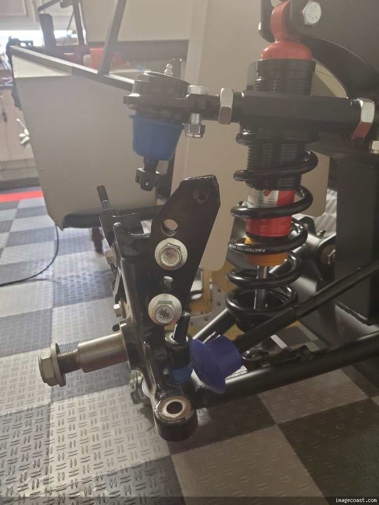
What I don't know is which set of holes the adapters use. Do you?
-
Not a waxer

SN95 spindles use the lower set of holes as shown…BUT…I was under the impression that pin drive adapters could only be used with SN95 spindles…
EDIT
After looking into it further it seems that the pin drive width adapters can be used with either Fox or SN95 spindles. Your installation is correct. Your adapters appear correct as well…standard width have much more offset between the 4 bolt holes and the ball joint hole. You should be hood to go.
Hope that helps!
Jeff
Last edited by Jeff Kleiner; 07-09-2022 at 05:30 AM.
-
Senior Member


Originally Posted by
Jeff Kleiner

SN95 spindles use the lower set of holes as shown…BUT…I was under the impression that pin drive adapters could only be used with SN95 spindles…
EDIT
After looking into it further it seems that the pin drive width adapters can be used with either Fox or SN95 spindles. Your installation is correct. Your adapters appear correct as well…standard width have much more offset between the 4 bolt holes and the ball joint hole. You should be hood to go.
Hope that helps!
Jeff
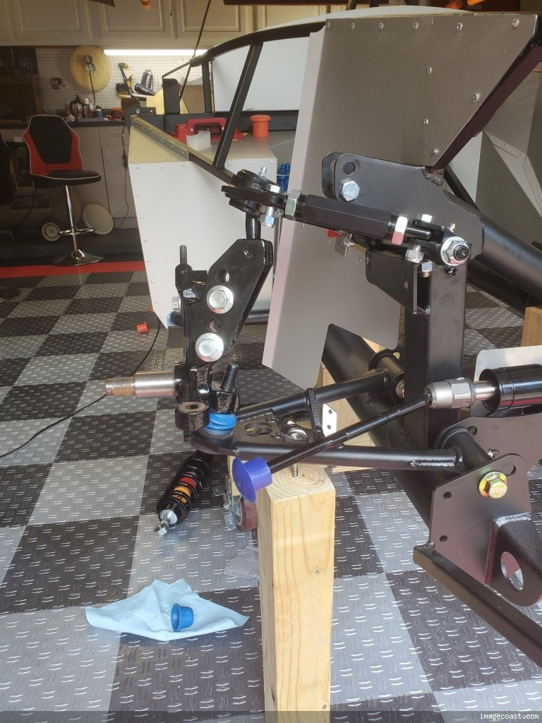
I'm thinking I need to move the adapters down a set of holes, what do you think?
-
Senior Member

Yes, the upper set of holes on the adapter.
Mrk III, 331 stroker, Borla stack injection, T5, 3:55 IRS, Power steering and brakes. Kleiner body & paint
-
Not a waxer

Second and 4th holes from the top are for SN95 spindles; top and 3rd holes down are for Fox.
Jeff
Last edited by Jeff Kleiner; 07-09-2022 at 12:32 PM.
-
Senior Member


Originally Posted by
rich grsc

Yes, the upper set of holes on the adapter.
Thanks Jeff, I'll move them.
-
Senior Member

You guys wanna hear something funny on this? Well, first off, what's not funny is that in 10 yrs FFR has not fully changed or amended the manual for the 289 or PIN drive. Second, because of this, when I did my last 289 in 2014, they had the one piece brackets pictured. Now they've at least added the two piece SN95 but the connecting arm pictured is wrong. Finally, they forgot to put the correct block/brackets in my kit so I was twice as confused thinking they changed it or something.
So I'm emailing Dan back and forth and he assures me I have the right spindles and I'm telling him I didn't receive these connecting arms as part of the two piece kit. THEN I SAW THIS POST AND THE BOX BRACKET AND IT ALL CAME RUSHING BACK TO ME. The same damn thing happened 10 years ago! LOL. With nothing on the inventory description or pictured in the manual I had no idea what I needed. Tony Z sent me the box brackets back then and so I had and extra set. And then I saw this and I'm like "Wait a minute, I remember these!" I ran down to the garage and found the second set he shipped me (and that I almost threw out while cleaning the garage in prep for this build!). It's like Deja Vu all over again!
-
Senior Member

I went to order the pin drive suspension and it wasn't listed. I called Dan and he said they no longer sold it and added pin drive wheels were illegal and I wouldn't pass inspection with them. Literally the next day I was watching one of Dave Smith's Q&A videos on FB and one of the questions was about the pin drive front suspension. He said if anyone wanted it FFR would supply it. I sent the video to Dan and said that's what I want!
No one, and I mean no one at Factory Five knew what to supply. I found the part number (13242) in an old brochure I had from a few years ago and gave it to them. Still took them months to find the BOM for the part number. But even this BOM isn't 100% correct, it took a bit to get all of the required parts that were actually required.
In addition to 13242 I also received 14507 Front Spindle Components which included the front spindles and hubs. No where on any paperwork I ever received were the 12507 Pin Drive Spindle Adapters, they just magically showed up.
The manual is useless as is FFR technical support when it comes to pin drive. Thank God for Jeff Kleiner!
-
Post Thanks / Like - 0 Thanks, 1 Likes
 BRRT
BRRT liked this post
-
Senior Member

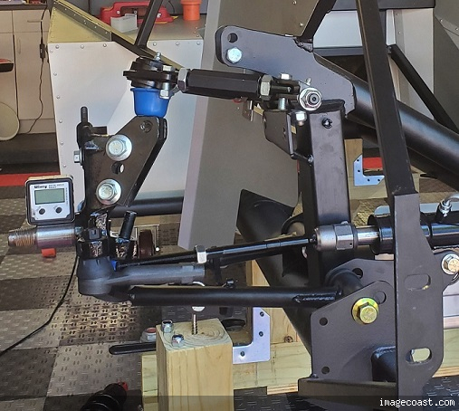
Where I ended up.
-
Senior Member


Originally Posted by
Mike.Bray

Where I ended up.

So you cut the adapters? I don’t remember having to do that on mine but it was a long time ago. Are driving yours now. How is it?
-
Senior Member


Originally Posted by
ehansen007

So you cut the adapters? I don’t remember having to do that on mine but it was a long time ago. Are driving yours now. How is it?
Yes, there was a slight interference, I could have ground the spindle casting but decided to cut the adapters since the spindles were powder coated. And less unsprung weight
It drives very, very good. Straight as an arrow and zero bump steer. Only issue I've had was the steering wheel was slightly off center but I've corrected that now and reset the toe.
-
Senior Member

Beautiful! Maybe I did cut them! Lol. after looking at both UCA and LCA in different holes I got a smaller variance with mounting it your way. About 18degrees and 19degrees vs 14 and 19. So that should be right even with upper arms being shorter. How much caster were you able to get? I remember running as much as I could with my e-power steering setup and I got to about 9 degrees I think.
Last edited by ehansen007; 10-08-2024 at 05:41 PM.
-
Senior Member

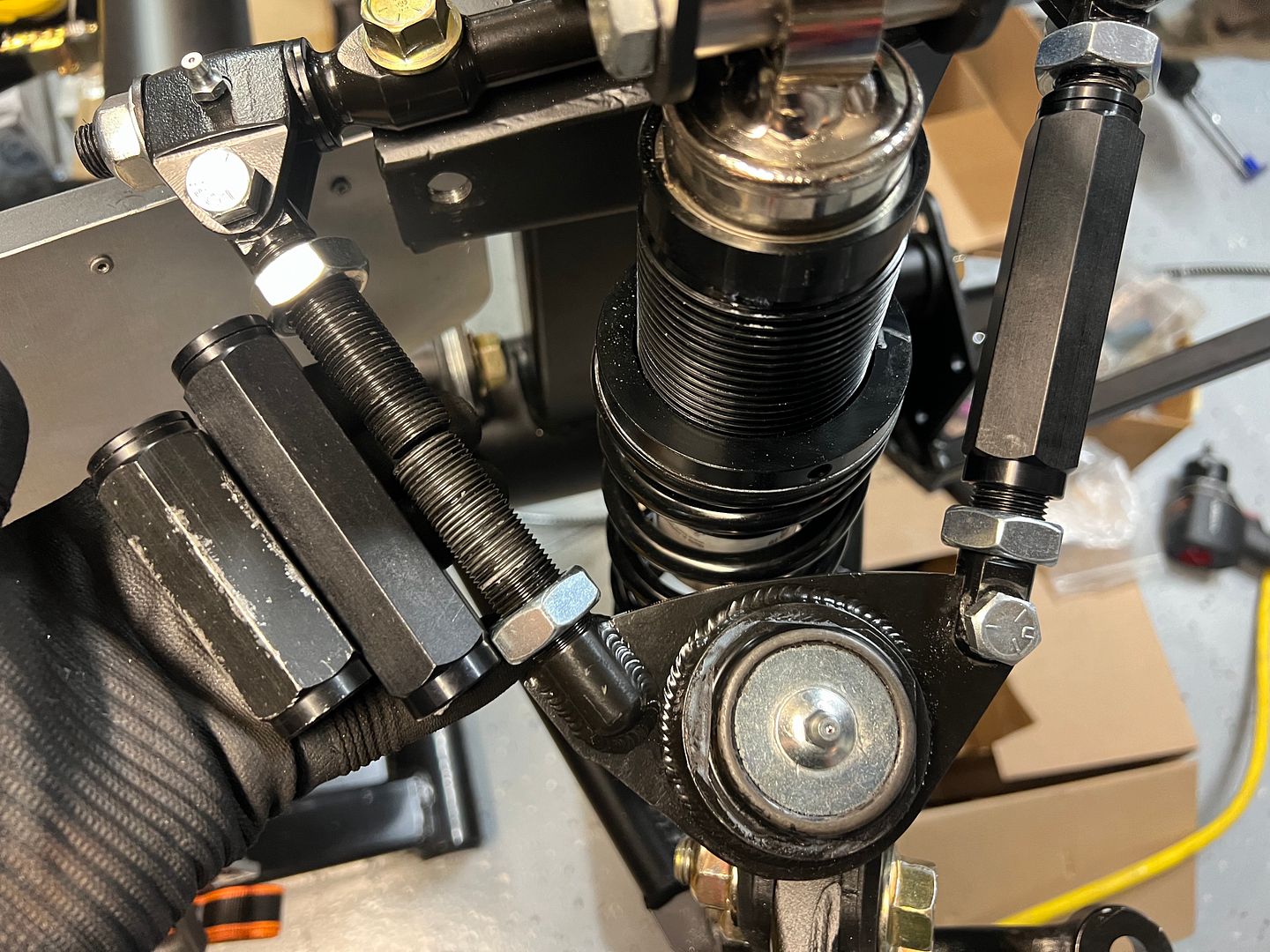
Okay everything went on okay (the hubs were super tight) but now I’m thinking I need to cut the back threads to allow for more caster like I did last time. I have the smaller turn buckle. Thoughts? Again with power steering I can add caster to make it track straight.
Last edited by ehansen007; 10-08-2024 at 10:50 PM.
-
Senior Member


Originally Posted by
ehansen007

Okay everything went on okay (the hubs were super tight) but now I’m thinking I need to cut the back threads to allow for more caster like I did last time. I have the smaller turn buckle. Thoughts? Again with power steering I can add caster to make it track straight.

Oh yeah, I had to cut quite a bit off of the male threads. I was able to get 7.5 degrees of caster.
If you give me a day or so I'll get you the lengths of my sleeves for a reference.
-
Senior Member

Thanks, I'm gonna brew up a definitive pin-drive thread so no-one will have to go through this again. I'd like yours and Kleiner's input.
-
Not a waxer

Hey E! Yes, I always recommend cutting back the male threads as Mike said so that they don't bottom out internally in the sleeves. I've shown this marked up photo a number of times to give guys some dimensions that gets them real close when roughing in alignment:
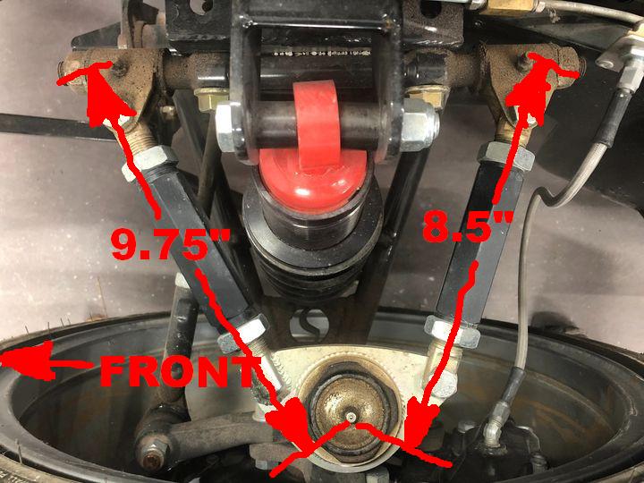
Note that this is for a conventional Mk4, not pin drive so the numbers will not be the same. Maybe at some point Mike can measure his and provide dimensions. Referencing from the zerk fittings makes it pretty easy.
Jeff
-
Senior Member

I will get some measurements later today.
-
Senior Member

Yes I think that for the 289s it's narrower so you have to get more. The adjusters you have might be a bit long but again, I'm not sure if anything's changed since my last build.
-
Senior Member


Originally Posted by
Jeff Kleiner

Hey E! Yes, I always recommend cutting back the male threads as Mike said so that they don't bottom out internally in the sleeves. I've shown this marked up photo a number of times to give guys some dimensions that gets them real close when roughing in alignment:

Note that this is for a conventional Mk4, not pin drive so the numbers will not be the same. Maybe at some point Mike can measure his and provide dimensions. Referencing from the zerk fittings makes it pretty easy.
Jeff
Change the 8.5" dimension to 8.0", that's what I've got.
-
Post Thanks / Like - 0 Thanks, 1 Likes


 Thanks:
  Likes:


 Reply With Quote


