-
Member

TTimmy’s MK3 Basket Case Build Thread - SEAT HEATERS
Shortly after starting my coupe build two years ago, I knew that I would be building another vehicle. I have found the build process to be just as enjoyable as driving (other than fitting the hood). Thus, as my coupe project wound down for the summer driving season I started considering other projects. (I still need to tackle my couple bodywork and plan to do so this winter)
I recently seized on the opportunity to buy a Mk3 basket case that came up on Facebook Marketplace. It was about an hour away so it was quite easy to check it out and then flatbed the vehicle back home. Since it stayed “in-state” I am hoping for an uncomplicated titling process; though I’m sure PennDOT has other plans for me.
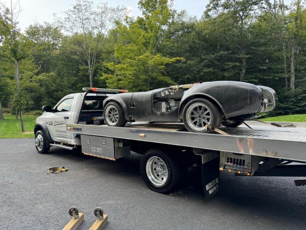
I’m going to take a shot at maintaining a build thread. I’ve found the other build threads to be a monumental help with my recent coupe project and thought that I would help contribute. I also hope that others that have experience with the roadster will chime in with guidance as I work through this build.
My general build philosophy for this build is to use the parts I acquired as part of the deal and minimize the purchase of additional parts if possible. The car is reasonably well optioned and I don’t think any major changes will be necessary.
Acquisition Details
SN: F5R1004911RD
Year of Manufacture: 2004
This was the owners second FFR build
While the year of manufacture is 2004, it seems most of the build work started around 2019 from what I can tell by going through miscellaneous receipts.
Options
- Here is what I have been able to piece together thus far from the roller, boxes, bins and buckets that I purchased:
- Blueprint 306, carbureted, New in ~ 2020
- Tremec TKO acquired through Blueprint
- 8.8 with unknown gearing, Rebuilt with new bearings, seals and shims
- Three link rear suspension
- Tubular front lower control arms
- Koni Red Shocks
- 17 FFR Halibrand reproductions
- Nitto 555s
- Ron Francis wiring harness
- Russ Thompson signal assembly
- Chrome hood hinge assembly
- FFR Street Performer high back seats - both are new, however one did not age well and is rough shape
- Carbon fiber dash
- Carbon fiber door panels
- Carbon Fiber fender spats
- Ultra-lite gauges
- Wind wings
- Wipers
- Chrome bumpers, Front hoop damaged
- Full width rollbar - I don’t think I’ve ever seen this before
- Ceramic coated exhaust and headers
- Carpet kit
Current State
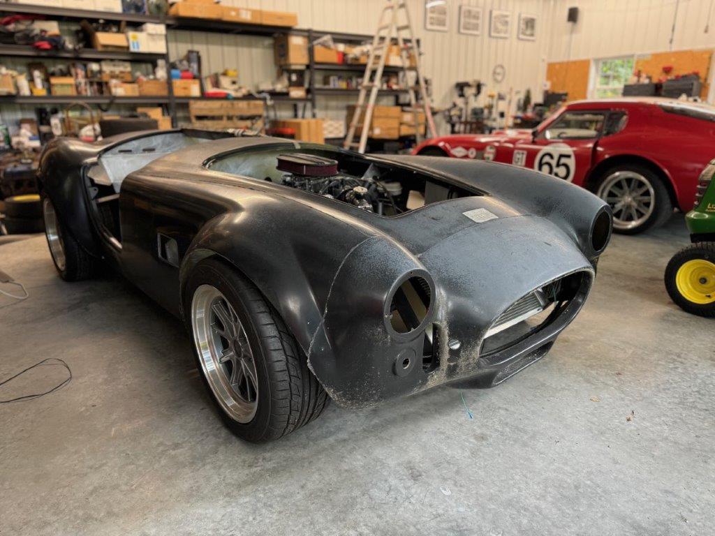
The car was received as a roller with the engine and transmission mounted. The engine starts and runs. The fuel system and brakes are installed. The dash is partially wired though not functional. The car has the general “barn find” patina to it.
Issues
Much of the car needs to be disassembled and reassembled in order to validate proper assembly and address a number of issues that do not align to my build standard. While the suspension components are installed, I have found that most parts have not been torqued down. Copper crush washers have been used throughout the build for some reason and the wrong hardware has been used in at least a few places. The brake, fuel and engine plumbing is a bit of a mess and needs to be fixed. I will also rework the wiring in order to tidy up the routing and make some additions for seat heaters and a reverse light perhaps.
Current Activity
Thus far I have cleared out some space for the car and parts. The body has been thoroughly washed down and the chassis components have been cleaned up. I made a first pass at sorting out the boxes, bins and buckets of parts.
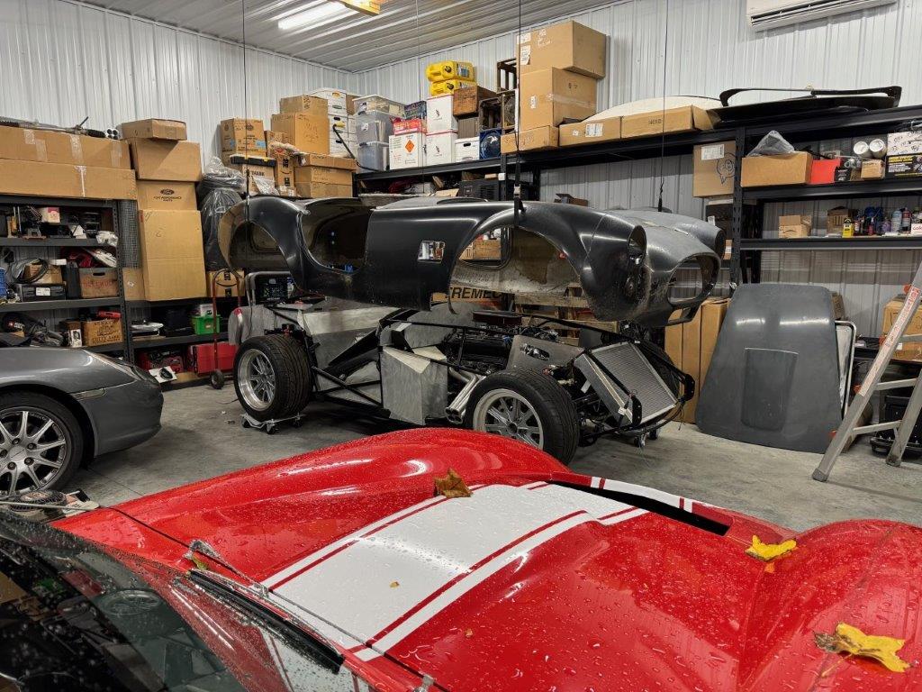
I have also installed a block and tackle system so the body can be stored up high. The system was designed for a Wrangler hard top and it works very well.
Next Steps
The next steps are to continue the inventory and sorting of the parts and to perform a more detailed assessment of the car
This will also be my first attempt at properly embedding photos inline with a post. Hope it works.
Stay Tuned!
Last edited by TTimmy; Yesterday at 09:18 PM.
-
Post Thanks / Like - 0 Thanks, 3 Likes
-
Member

-
Member

Build Plan - Body, Interior & Electrical
Body
I plan to tackle all the body work myself once I’m further along. So far all I have done is wash down the filth that covered it.
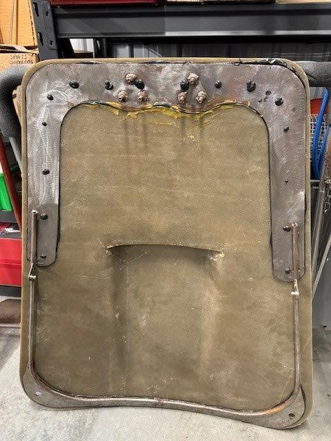
For some reason the kit came with two hoods and two internal support frames - not sure why. One hood has a partially delaminating support frame and the other hood and support are not yet attached to each other. However, that second support frame has a bit of surface rust. Given that the hardware is already delaminating I hope I can pull it off and clean it up. Otherwise I can fall back to the other hood.
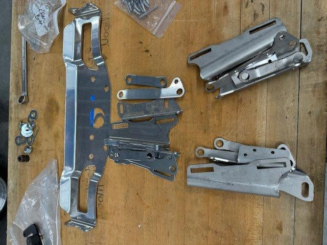
The kit also came with a steel hinge setup as well as a chrome hood hinge setup. I have yet to find the nuts and bolts for the hinges, but all the other parts are here. So I will need to acquire the hinge hardware bits: nuts, bolts, ball standoffs for struts, etc.
The kit came with chrome bumpers and overriders. The front bumper hoop has a pretty big dent in it so this will need to be replaced or fixed.
As far as the body treatment goes, I plan on applying raptor on the underside of the body, wheel wells, etc. I have no plans yet regarding the final color scheme.
Interior
Following along with the same theme here… I plan to use what came with the kit. This includes the carpet kit, carbon fiber dash, gauges, etc. I will apply lizard skin to the sheet metal.
I made my coupe trans tunnel cover removable by affixing it with U-shaped brackets designed to attach golf cart windshields. The brackets attach to the frame very tightly but allow the cover to be popped off. I plan to do the same thing here.
The high back Street Performer seats may get replaced. One is fine and the other has a bit of damage - most likely from moisture.

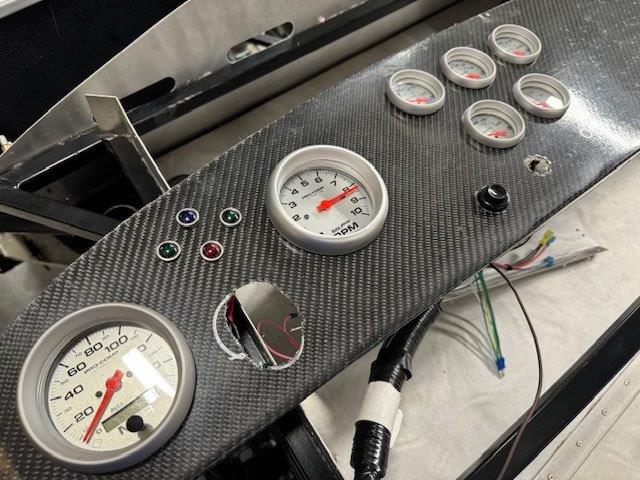
The CF dash looks pretty slick but has a few issues. The holes that were cut for the gauges and switches are just a bit too large or just not clean cuts. The result is that the cutouts are somewhat visible. I hope with a bit of tweaking I can get the bezels to cover things up. I have an aluminum dash as a backup but hope I can make the CF unit work out.
I am also considering the purchase of a heater/defroster unit and would appreciate any thoughts on the FFR unit versus aftermarket stuff that is out there.
Electrical
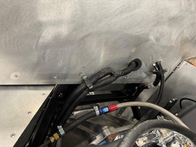
The Ron Francis harness should work just fine. The routing does need to be cleaned up a bit. Seems the prior builder cut all the grommet holes too large so I need to find some larger grommets or patch things up. I will be adding a circuit for a reverse light as well as seat heaters. I’m considering the Breeze battery relocation kit. Other than that I don’t foresee any other changes.
-
Member

-
Senior Member

Sheesh. In the build school they kept saying anyone could build one of these...after having completed the mechanical part of the build and knowing how many small decisions one has to make with every little part, I wouldn't say that anyone could (or should) build one. You definitely need to have a basis of knowledge for lots of different things to even know the right questions to ask during the build and ensure things are working as they should. Or will continue working even if they work right this minute. It sounds like taking over another project would be more work than starting a new one. That's part of why I did this instead of buying a car to restore: I didn't want to spend weeks or months disassembling before I could even start to make progress.
Thanks for updating, I'll be following along!
-
Member

JMD,
As far as taking over another project would be more work than starting a new one… that is definitely the case with this project! I understood that when I took it on. I performed a thorough inspection and knew that I would be taking it back down to the frame for the most part. The justification for going this route was cost. I got a very fair deal on a well optioned car that included the powertrain. This being my second build, I am comfortable with that approach… I just need projects to keep me busy I guess.
-
Member

-
Senior Member

I love this thread because I love rehab work. This is by far more work than doing it yourself new. That being said this poor lost MK3 didn't do anything to deserve those brake lines. This is really cool, I wish you luck. I am looking forward to seeing what she turns into.
Just out of curiosity what percentage of a discount was this compared to new? Was it a good financial deal or just an opportunity to rescue a lost hotrod?
-
Senior Member

It appears that your new project came pretty well equipped, and it's actually running. That's a bonus not everyone has when they take on a half done build.
The full width roll bar must have been an aftermarket one the previous builder had sourced. Some replica's came with that style bar. The hoods designed with the metal reinforcement I thought were used on much older models, like MK1's.
FFR6803RD, MK 3.1, 302 EFI, fr/rr disc brakes, WC-T5, c/w Hurst Competition Plus shifter, 3 link rear, Koni adjustable coil over shocks, dual roll bars, BBK 4-4 headers, 3.55 rear gears, BBK rear lower control arms c/w poly bushings. Ivy Green Metallic Arrived-02/08, On road 09/2010
-
Member


Originally Posted by
Blitzboy54

I love this thread because I love rehab work. This is by far more work than doing it yourself new. That being said this poor lost MK3 didn't do anything to deserve those brake lines. This is really cool, I wish you luck. I am looking forward to seeing what she turns into.
Just out of curiosity what percentage of a discount was this compared to new? Was it a good financial deal or just an opportunity to rescue a lost hotrod?
So, the first time I searched Facebook Marketplace for "factory five" this opportunity showed up in the search results. I was only an hour a way. It was meant to be. And maybe I did feel a sense of duty to rescue this poor beast!
I do enjoy this kind of project and the rework does not phase me. I like solving problems and this is a bit of a puzzle in that I was not really sure what I was working with. We used to buy old lego kits at garage sales with our kids and then "puzzle" them back together or into something else entirely. I think that is fun. Being a Mk3 it's a little tougher to find information - Many of the Mk3 builds are on the old forum and most pictures are gone. However, most of the Mk4 info still applies.
As far as "discount" goes, I probably saved about 50% compared to a similarly optioned car at today's prices. Must keep in mind that this is a 20 year old Mk3 with relatively new powerplant, transmission and tires so certainly not an apples to apples comparison. It was a very well optioned car at the time. Now, had I speced out a new roadster from the FFR site myself I probably would have added IRS and a bunch of other expensive stuff. So considering that, I saved even more money!
I would definitely consider going this route again for a future build. That said, buying a basket case is probably not for everybody.
-
Member

Donor Master Cylinder Question
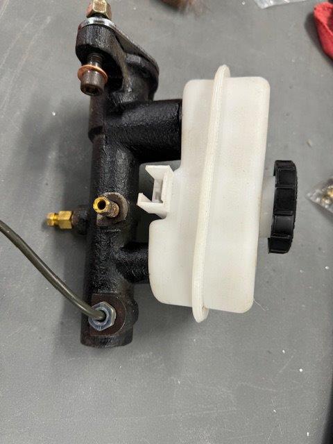
I’m looking for guidance on plumbing up the donor master cylinder. The master cylinder I have has three ports. The prior builder had one port running to the rear brakes and the remaining two running to each front brake. I have not worked with this type of MC before.
First, I want to make sure that this is the correct way to handle these connections.
Second, how does one adjust front/rear brake bias with this type of setup?
-
Member

-
Senior Member

Quiet a cool project TTimmy. Looks like you're off to a great start. I have been starting to look for another Cobra in about the same condition and configuration as the one you got. Assessing the parts count and condition of everything you get would be a major determining factor in cost, but if you figured you paid about 50 cents on the dollar, and got all the parts, I think you did pretty good. The big question I have is the COO in the original owner's name, and titling after you have completed the project. Have you looked into this in Pa.? I live in Md. and have not checked into how to title a vehicle that was not completed by the original owner with a COO that is in his name. Something I need to do before pulling the trigger on a buy. I have seen some horror stories on here from some guys who had a very tough time getting their project car titled after the COO was in someone else's name. Anyway, good luck on the car and please post if you have any issues in titling. P.S. Take those leaves off that beautiful coupe.
FFR 9883 MKIV ,427 Windsor engine
TKX 5 speed, Three Link 3.55 gears
Power Steering, Leather Seats
18" Wheels and Tires, Drop Trunk
Fun Package
-
Member

Titling a used kit in PA

Originally Posted by
ggunter

Quiet a cool project TTimmy. Looks like you're off to a great start. I have been starting to look for another Cobra in about the same condition and configuration as the one you got. Assessing the parts count and condition of everything you get would be a major determining factor in cost, but if you figured you paid about 50 cents on the dollar, and got all the parts, I think you did pretty good. The big question I have is the COO in the original owner's name, and titling after you have completed the project. Have you looked into this in Pa.? I live in Md. and have not checked into how to title a vehicle that was not completed by the original owner with a COO that is in his name. Something I need to do before pulling the trigger on a buy. I have seen some horror stories on here from some guys who had a very tough time getting their project car titled after the COO was in someone else's name. Anyway, good luck on the car and please post if you have any issues in titling. P.S. Take those leaves off that beautiful coupe.
So perhaps a leap of faith, to some degree, that I can get this car titled smoothly in PA. My coupe (purchased from FFR) went very smoothly... enhanced inspection at Ralph's garage about a mile from here and six weeks later I had the title and plates from Harrisburg. Clearly the new one will be more complicated. At the end of the day this is tax grab by the state... they just want some revenue. If the kit car process (Specialty Constructed Vehicle with Manufacturers COO in PennDOT parlance) fails outright, I have several other avenues for titling the vehicle:
- Specially Constructed without COO. In this case I provide receipts for all parts and any relevant salvage titles (I have one for the rear end)
- Street Rod
- Collectable
Here is what I did to best position myself for this process on this resale kit:
- I have a bill of sale with all relevant info from the vehicle, seller (estate executor), original buyer (deceased) and buyer(me)
- I have the original COO
- I have a death certificate of the original owner
- I have copies of the Letters of Administration (granting Authority provided to estate executor)
I am hopeful that will all this; and with all of this being withing the state of PA, that PennDOT will figure it out. If not, let's not forget, we have elected officials that will act on our behalf to help sort out any nonsense. I will call on them if necessary.
Stay tuned and I will let you know how things pan out.
TTIMMY
-
Member

-
Member

Paneling Like it's the 70's!
Paneling like it’s the 70’s!
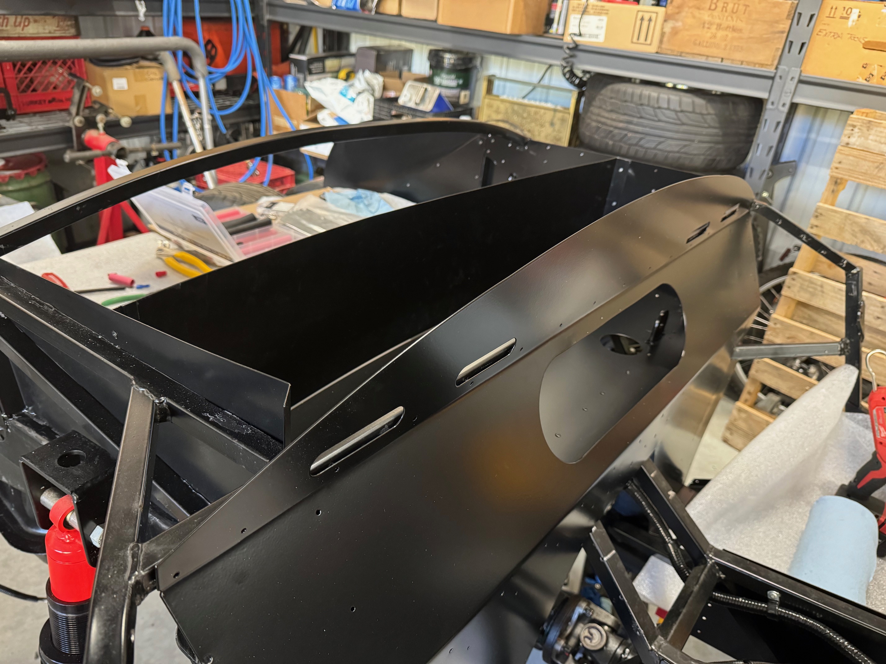
Most of this week was spent refitting the aluminum panels now that they are back from powder coat. I guess I didn’t do a super-thorough job of cleaning off the silicon caulk. They did groan a bit about the extra work but held to the original price. Good guys. Everything went back together smoothly. I patched some of the extra holes from the prior owner with either caulk, JB Weld or “false” rivets where appropriate.
Brake Lines & Fuel Lines and Related Bits
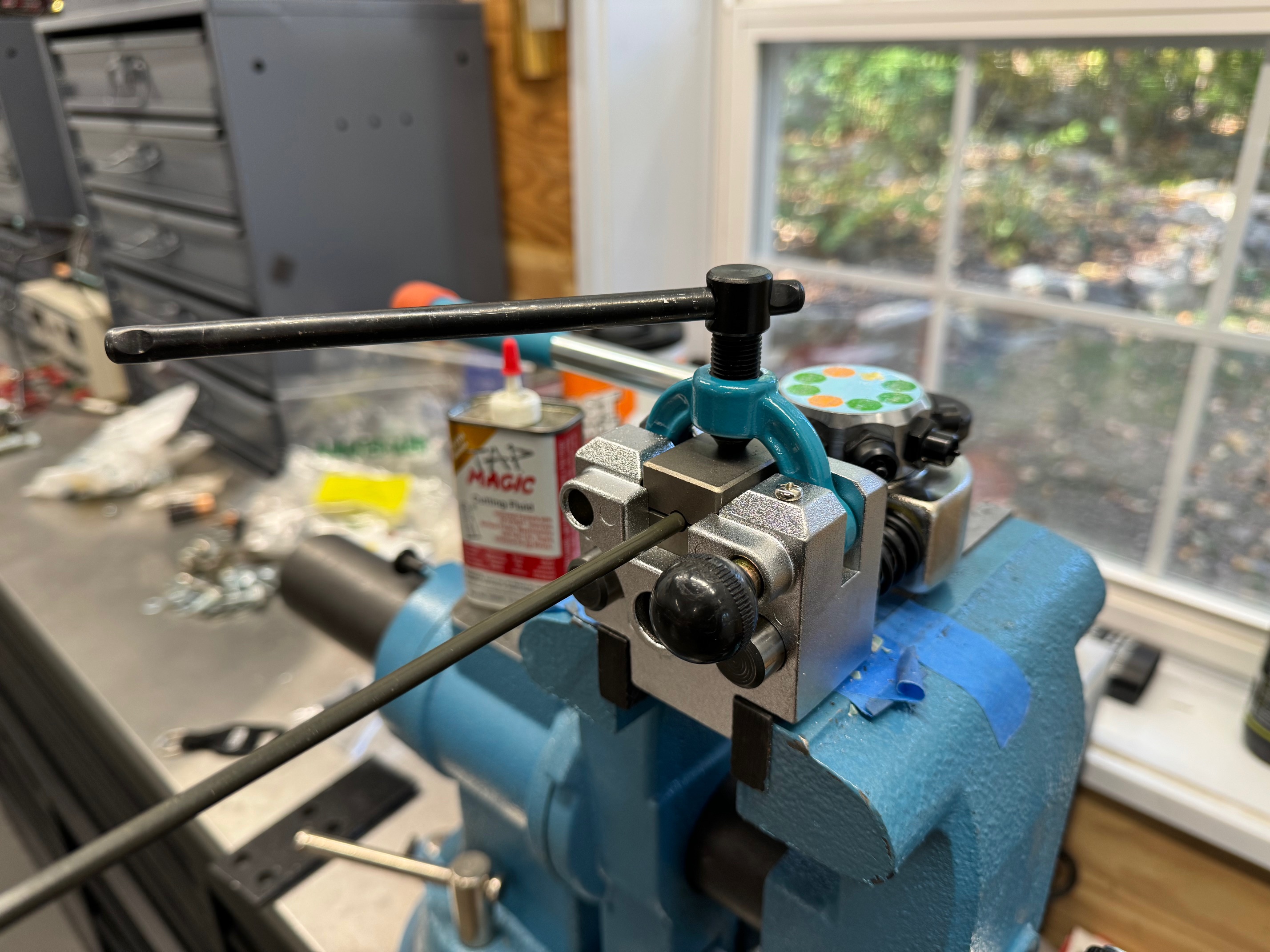
Once the aluminum was reattached, I focused on the brake lines and fuel lines. As mentioned earlier all these lines were redone from scratch in order to tidy things up… and remove an extra 20 feet of line. Between the old lines I salvaged and some leftovers from a prior build I didn’t need to buy anything. Remarkably I was able to build and bend all the lines without forgetting to put on the ends - Also didn’t let any of the ends get stranded on the wrong side of a bend! I don’t expect much from myself and consider accomplishments like this to be small miracles.
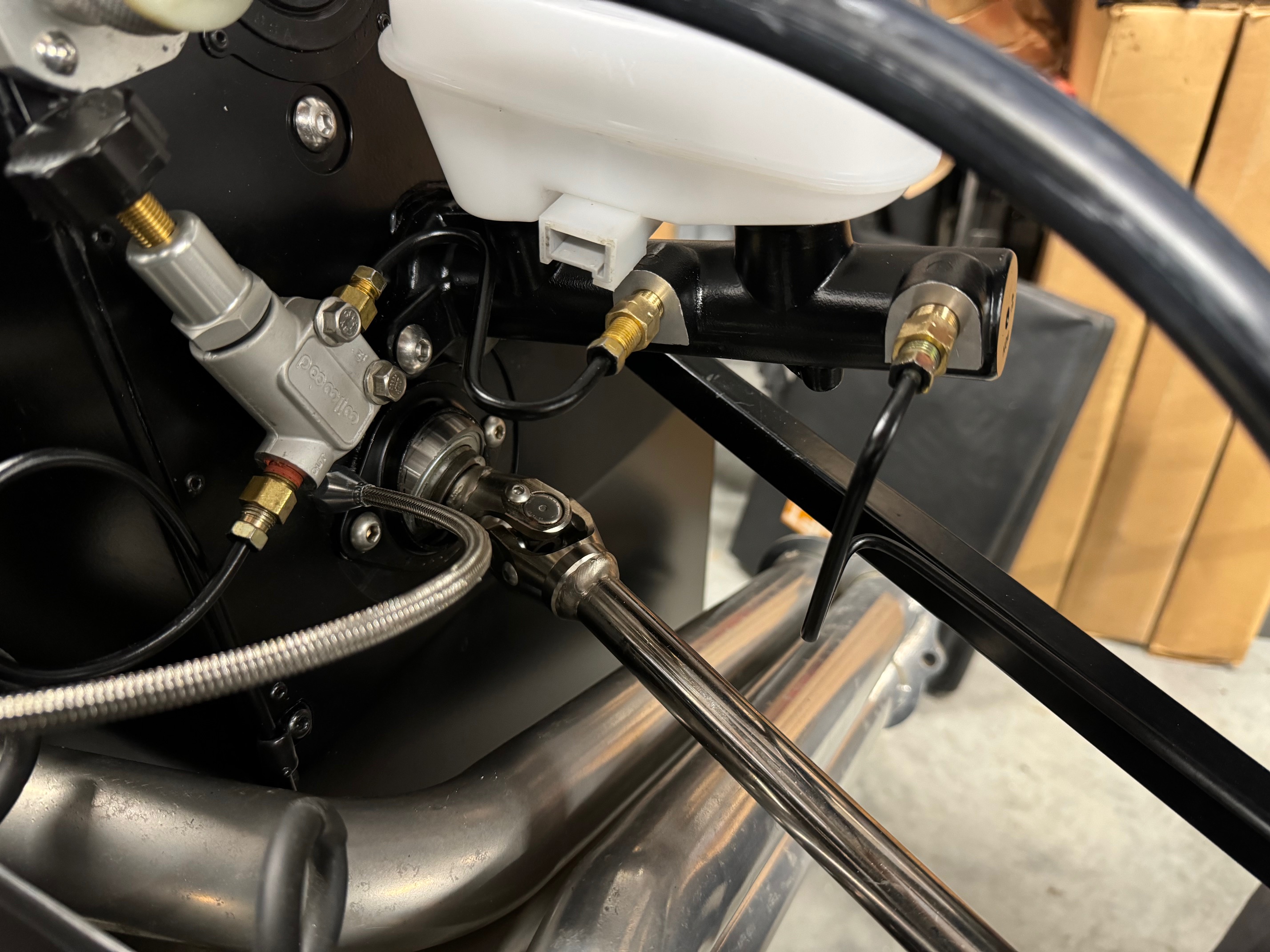
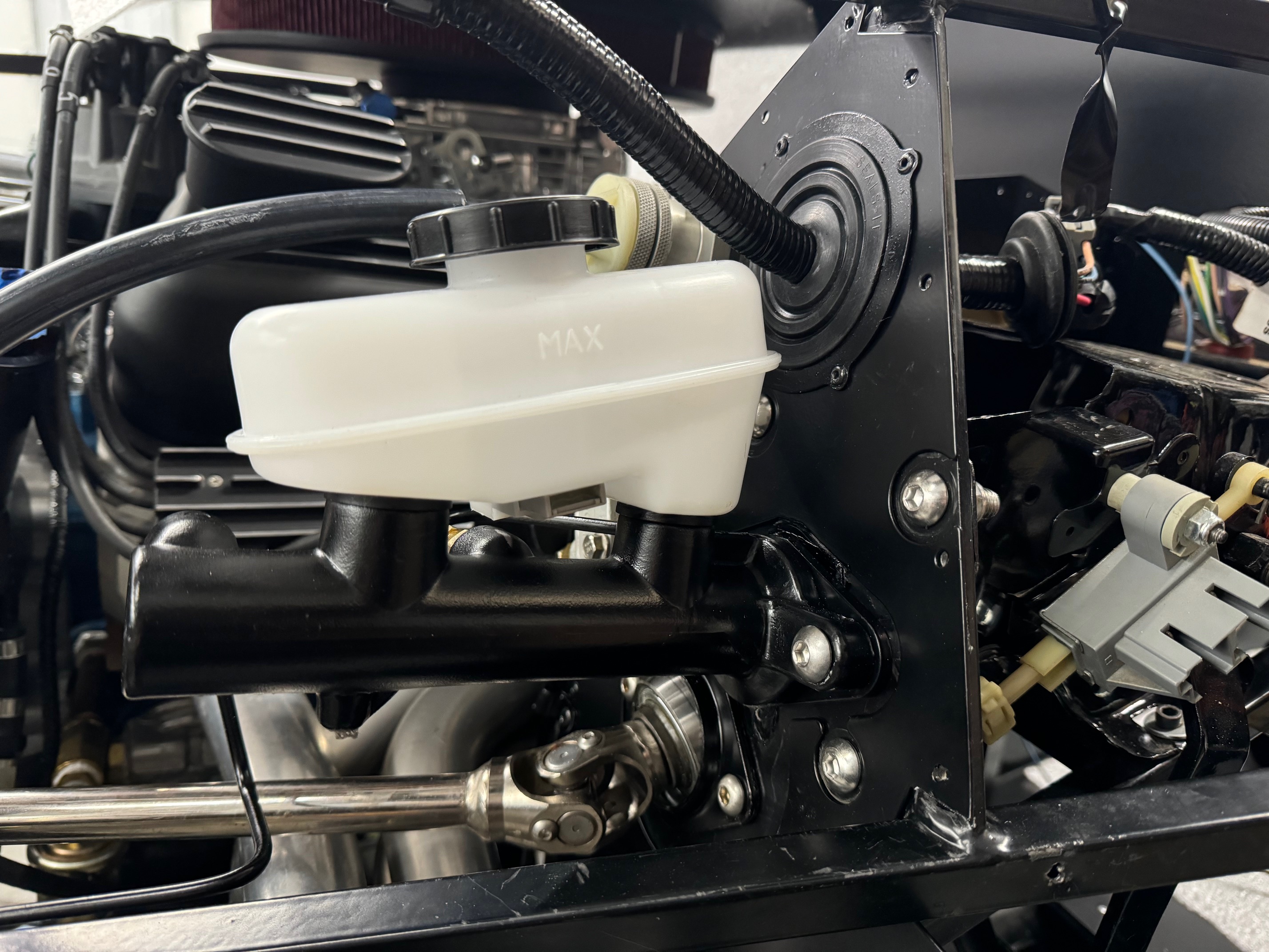
The new Cobra master cylinder is in place as well as a Wilwood proportioning valve. I never got clear direction on the importance of the proportioning valve for my setup, so thought it best just to add it now and that way it is there if needed. At some point I just need to ensure everything is tight and bleed it.
DS Footbox
With the aluminum and brakes largely wrapped up I was able to finish other components of the footbox. This included throttle cable, clutch cable, steering column and forward lighting harness.
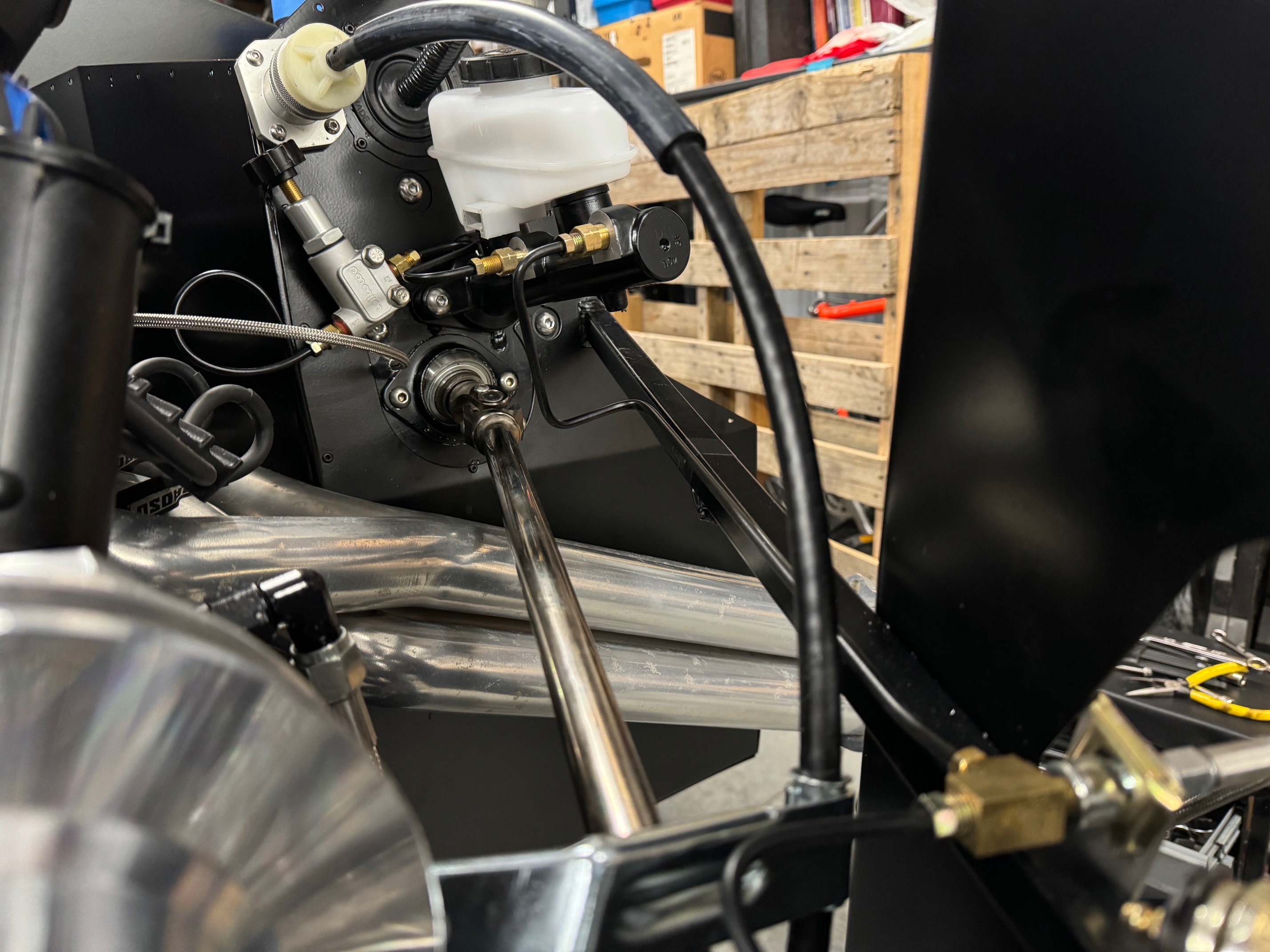
The new metal throttle cable mocked up. The old one was melted from sitting on the spark plug wire aluminum dressing/routing hardware.
I replaced the FFR clutch cable with a ford unit as so many have recommended. Plus another local builder, Scott E., had his cable get gummed up and required replacement. One less thing to deal with later I suppose. I didn’t compare side to side but the Ford unit must be longer - I was able to route it under the engine mounts instead of right next to the header like the previous one.
The steering column is back in place and seems a bit happier now that I moved the lower bearing to the inside of the footbox.
A lot of general clean up was performed. I filled up a bunch of unused holes on the front of the footbox. I used some JBweld to fill in the large gap around the area above where the master cylinder enters the footbox. Added a touch of paint and the hole disappeared.
Primary Power
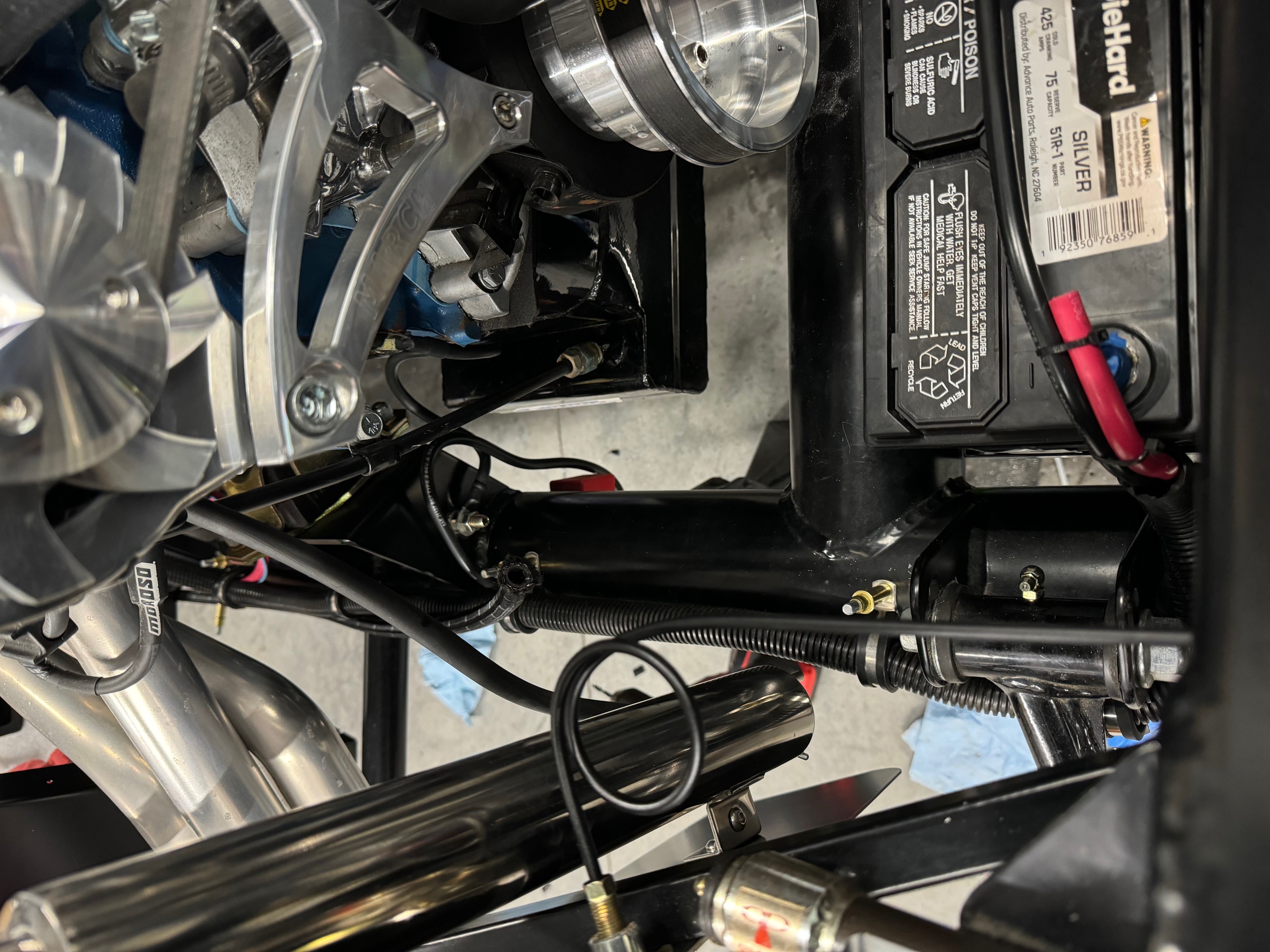
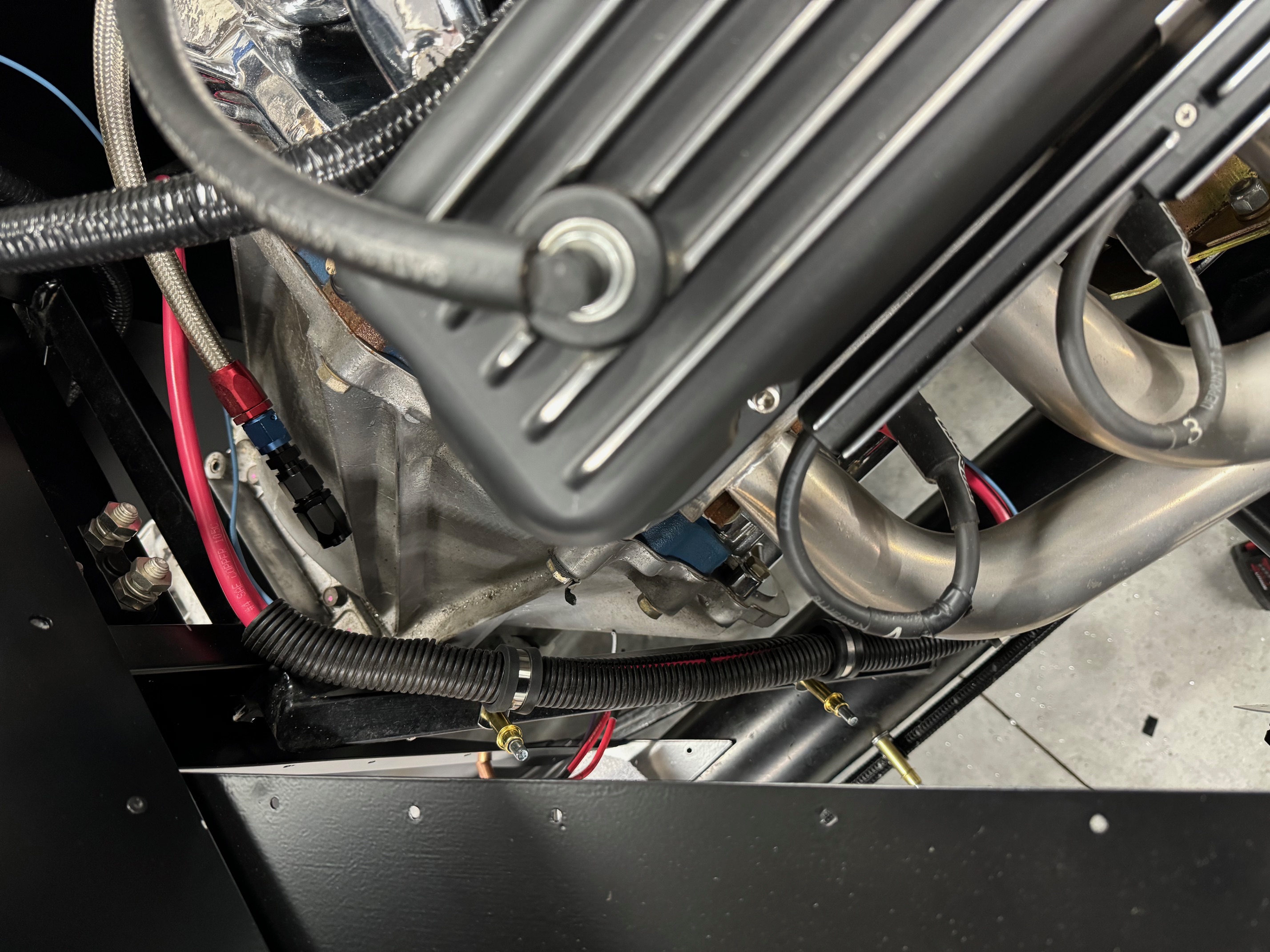
I mocked up the cable routing for the primary power between the battery and the cutoff switch. The switch will be located between the trans tunnel and dash. I have not worked out where everything will land behind the dash just yet. I need to pull down the dash and get the heater/defroster installed and see what space is left to work with. It won’t be as crowded as the coupe dash but still requires some planning.
Upcoming Work
This week I will spend some more time on the primary power; I expect to get everything mocked, measured, cut, terminated and wrapped… up to the cutoff switch anyway. I intend to get the heater in the firewall so I can start planning my other dash related electrical. Nothing too exotic planned, just adding some extra circuits for heated seats, reverse lights, courtesy lights, cigarette and USB outlets (dash and cubby).
I’ve been holding off on the radiator because I know it will get in the way of everything I am doing in the engine compartment. That said, I might get it all together and do a trial fit.
-
Member

E-Brake, Rad, Electrical and Defrost
E-brake
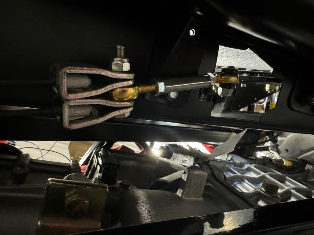
Not a very exciting topic but I am quite thrilled with my turnbuckle mod. So much so that I will probably retrofit my coupe. It was nothing too complicated, I replaced the heim joints with fresh ones; one right hand thread and one left hand thread. They are joined by a Left-Hand To Right-Hand Female Hex Thread Adapter. Added a couple lock nuts as well. All from McMaster-Carr. It allows adjustment without having to take the cable assembly apart. It’s really the way it should be properly supplied from FFR.
And I got it powder coated. Looks a lot cleaner and hopefully holds up better.
Radiator
Mocked up the rad with a Breeze shroud, hinge mount and lower support. It’s all really high quality stuff and seems a good value. The instructions are great and the contents of each kit are complete, including all hardware, rivets, etc. The packaging and identification of the individual components is very well done also. While I could have fabricated everything but the shroud, I probably could not have done it for much less money. And it super high quality.
For the upper hose I replaced the entire FFR setup in favor of a Moroso filler and a Gates hose that I cut up and pieced back together. Fewer connections and much cleaner looking. I’m much happier with this setup. The hose I had is a Continental E70621... For a 1975 Cadillac Fleetwood Brougham... because that's the kind of classy guy that I am! Needless to say, with an application like the Cadillac, you get lots of hose and lots of twists and turns... plenty of material to work with. I'm about $50 all in for the Moroso filler T and the hose. After working out which bits of the hose to use I cut out little half-circles on each side of the filler cap so that everything marries up cleanly. Used a sharpy to color the Moroso piece where there might be a visible gap. While I like the TDMotion piece a lot, it's hard to justify $500. Maybe another time. Only four connections, for which I’m using the Gates PowerGrip clamps. They are single use, so nothing gets fastened until I am certain I’m ready. For the lower hose I’m going with the Breeze kit. It was just delivered- Again, high quality stuff.
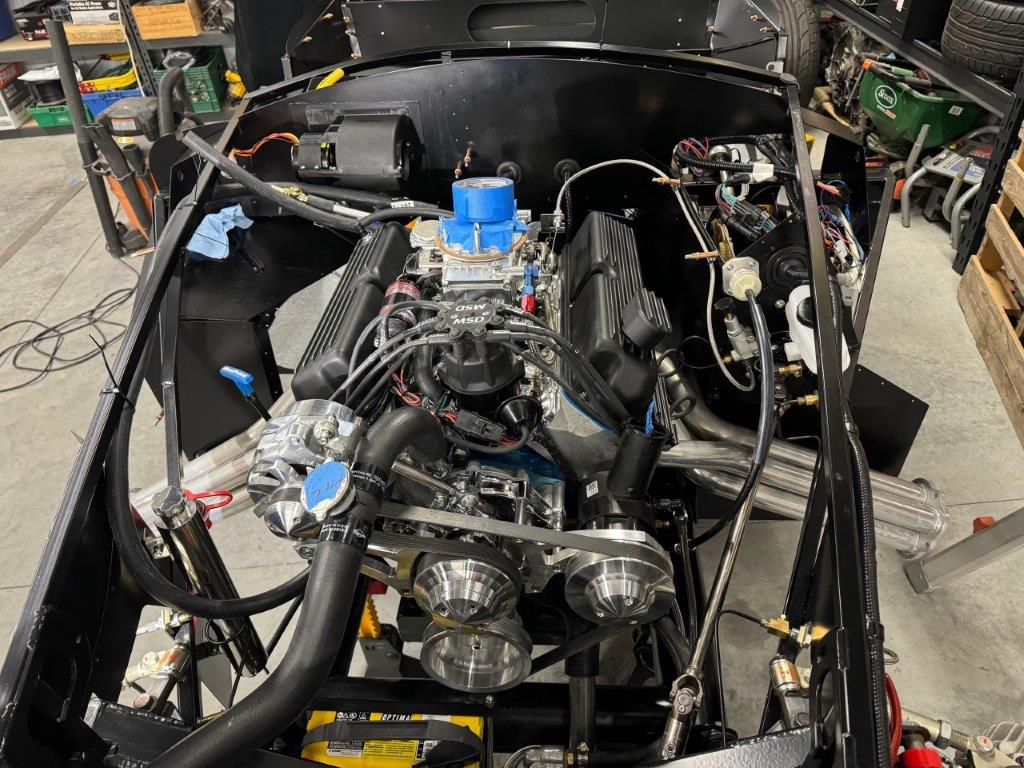
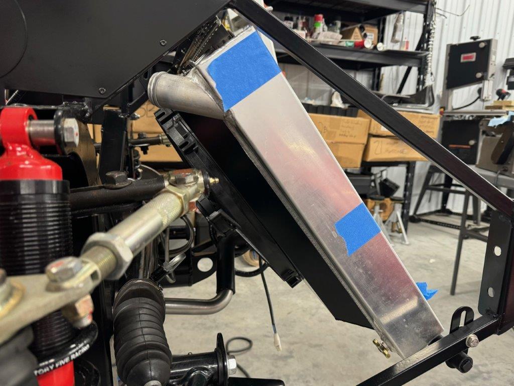
Primary power
Nothing too complicated here. I used the Breeze battery box - a very nice piece. The 4 AWG positive runs along the PS tube and back to the master cutoff above the trans. The switched positive runs back along the same path to the starter - along with the ignition start signal wire. Another feed will run to the bus bar behind the dash, feeding the RF harness and some other circuits. The alternator will feed through a 100 amp mega fuse. I also added a remote stud that connects directly to the battery positive stud. This will simplify jumping and charging. There are Plenty of ground sources in the are so I didn’t bother with the negative stud.
The negative runs to a stud on the engine mount, then across to the engine. I also ran the missing negative feed from the alternator to the ground stud - not sure how important this is since the alternator seems quite grounded as it. Regardless, the provisions for grounding the alternator are present and I used them.
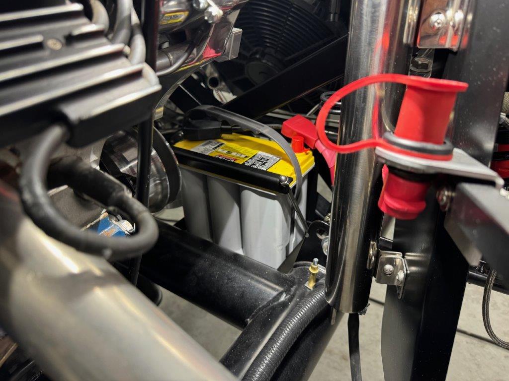
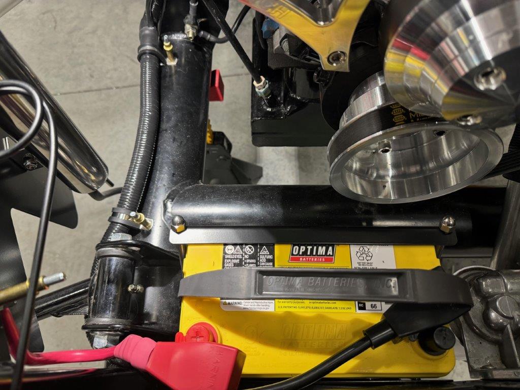
Heater Defroster
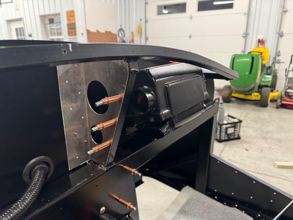
The heater/defroster was added to the build. This was more for the defroster than for heat. The setup seems quite basic but also all that is needed. At this point I have only mounted the heater core and roughed in the plumbing. The plan at this stage is to have the DS hose connection point to the PS and send that hose along the outside upper ¾ tube and to the water pump connection. I think I will put the valve on this section. The PS hose connection will cross to the DS and to the inside of the valve cover to the manifold port.
After mounting the blower it firewall was clearly not as sturdy as it should be. Build out a support and added some pass through ports for wiring and vents.
I’ve not yet worked out where to put the control switch. More to come on that later.
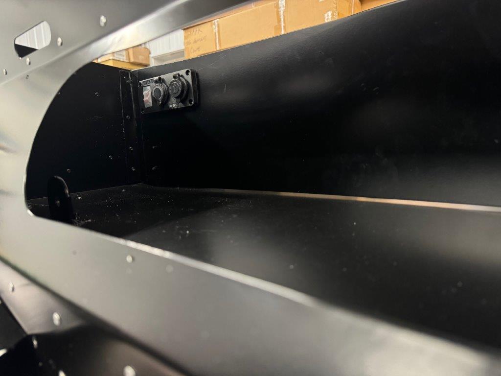
Cubby wiring
I added the cigarette lighter (if that is what they are called these days) and USB charger ports to the cubby area. It will run back to a circuit breaker off the main bus bar.
Next Week
I expect to wrap up the engine plumbing, including the heater. I will finish up the engine compartment wiring: starter, tach, senders, coil power, etc.
Time permitting, I will bleed the brakes and perhaps finish plumbing up the fuel system to the engine.
Last edited by TTimmy; 10-30-2024 at 07:22 PM.
Reason: Provided more product detail
-
Senior Member

Amazing rebuild! Car looks better than "new". Great work.
F5R #7446: MK4, 302, T5 midshift, 3.55 Posi IRS, 17" Halibrands
Delivered 4/4/11, First start 9/29/12, Licensed 4/24/13, off to PAINT 2/15/14!! Wahoo!
-
Post Thanks / Like - 1 Thanks, 1 Likes
-
Not a waxer

Ambitious project Timmy. I haven't been following along and just now checked your thread out---it's looking good! I've done complete builds on two roadsters that were started by others (one was really a disaster!) and I'd much rather start fresh!
In looking at your brake lines I see that you have the rear port plumbed to the rear and the front to the front. This is actually backwards. What difference does it make you may ask... The rear port is the primary chamber and the front is secondary. If you disassembled the master and looked at the cylinder pistons you'd see that the spacing of the seals on primary side result in a larger chamber which means that more fluid is moved for the same stroke. Additionally there is a spring between the primary and secondary chambers and the piston in the secondary chamber doesn't move until the primary has traveled enough to compress the spring; i.e. the brakes connected to the primary will be applied slightly before the secondary when you initially stab the pedal to energize the brakes. I'm afraid that with it plumbed as it is you're going to see premature rear lockup both due of the larger volume of fluid acting on the smaller rear caliper piston area as well as because of the rear being pressurized slightly before the front.
Jeff
-
Member


Originally Posted by
Jeff Kleiner

Ambitious project Timmy. I haven't been following along and just now checked your thread out---it's looking good! I've done complete builds on two roadsters that were started by others (one was really a disaster!) and I'd much rather start fresh!
In looking at your brake lines I see that you have the rear port plumbed to the rear and the front to the front. This is actually backwards. What difference does it make you may ask... The rear port is the primary chamber and the front is secondary. If you disassembled the master and looked at the cylinder pistons you'd see that the spacing of the seals on primary side result in a larger chamber which means that more fluid is moved for the same stroke. Additionally there is a spring between the primary and secondary chambers and the piston in the secondary chamber doesn't move until the primary has traveled enough to compress the spring; i.e. the brakes connected to the primary will be applied slightly before the secondary when you initially stab the pedal to energize the brakes. I'm afraid that with it plumbed as it is you're going to see premature rear lockup both due of the larger volume of fluid acting on the smaller rear caliper piston area as well as because of the rear being pressurized slightly before the front.
Jeff
... and I thought I got away without any brake line rework!
Glad you caught that, thanks for the feedback and explanation.
-
Member

PS Footbox Blues - Anyone have the dimensions for extending a MK PS Footbox?
Does anyone have the file containing the dimensions for extending a MK3 footbox?
It seems I am missing my PS footbox floor. After raving about my powder coat guys, - I used them for a few projects - they misplaced my PS footbox floor. This is not the end of the world as it looks pretty easy to fab a new one. However, I am always looking to make projects bigger and more complicated and I am considering enlarging the entire PS footbox. Only a couple more pieces, right?
Anyway, on the FFcars.com forum I see many references to a file with the dimensions for creating all the required pieces; but I cannot find the files, only dead links.
I hope someone here can point me in the right direction and save me a bit of effort. Any insight on this topic would be greatly appreciated!
-
Member

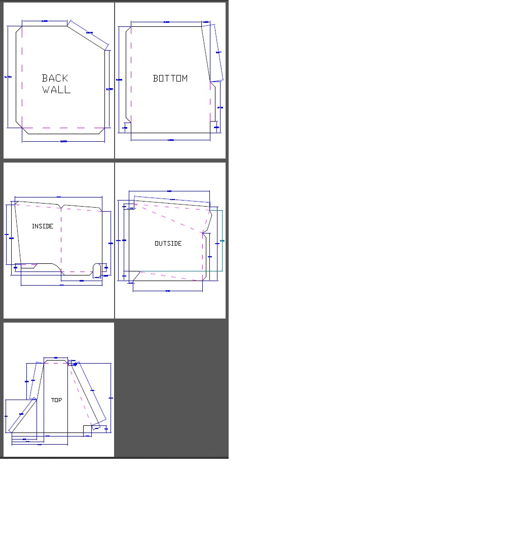
Extended Footbox Dimensions - DWG and PDF Files
I was able to locate the drawing files for the MK3 extended footbox if anyone ever has the need:
PDF File: https://drive.google.com/file/d/1BD4...23KqWzsNy/view
DWG File: https://drive.google.com/file/d/1ip6...ew?usp=sharing
Last edited by TTimmy; 10-30-2024 at 01:51 PM.
-
Member

Extended Footbox Build, Cobra Master Cylinder Rework, Plumbing and Wiring
The Case of the Missing Footbox Floor
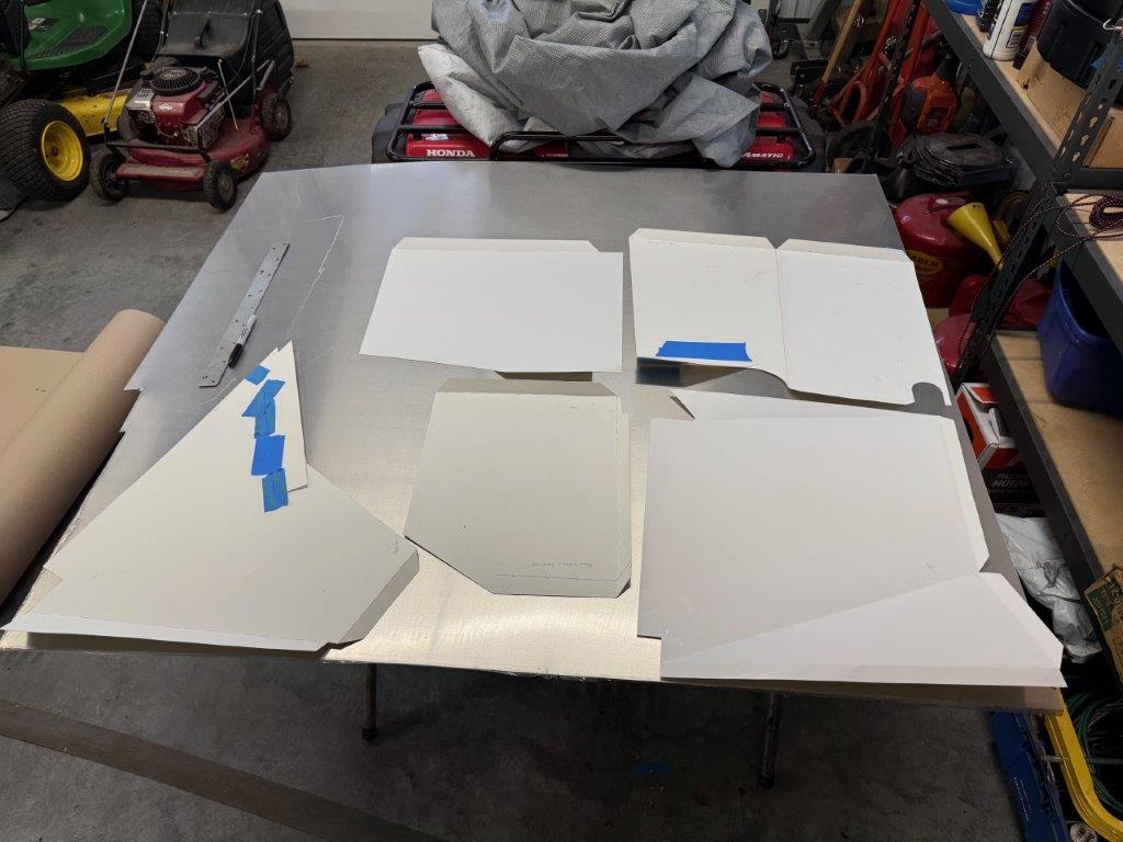
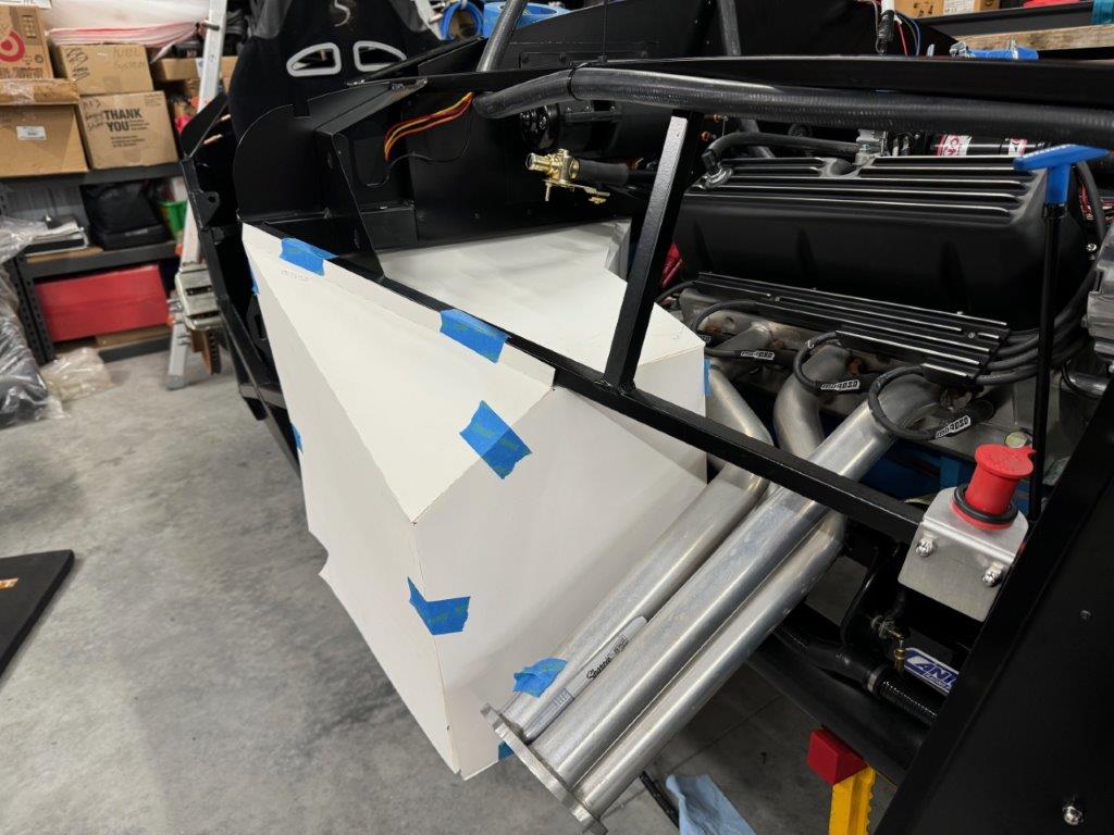
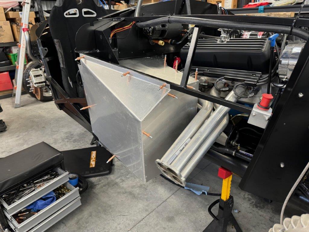
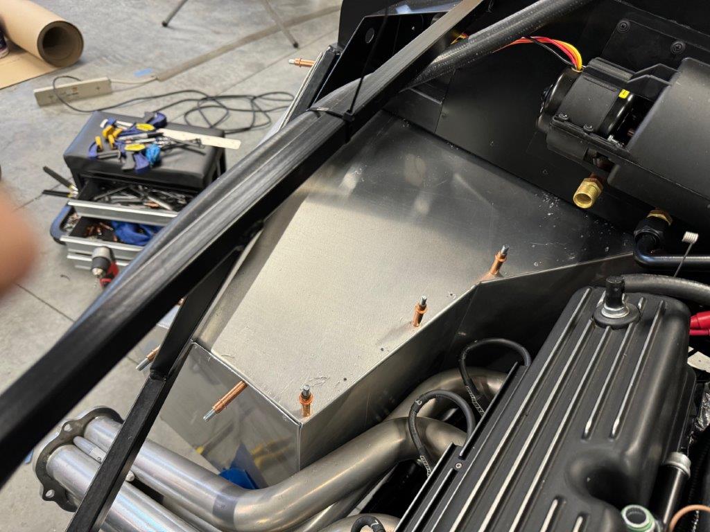
Forced to deal with my missing PS footbox floor, I decided if I’m fabbing up one panel I might as well fab up all five footbox panels and get a larger footbox out of the project. After much searching I found drawing files for the larger footbox on the old FFCars forum. I made a trip to staples, picked up some poster board and made up some cardboard templates. Surprisingly the templates fit quite well with only a couple minor adjustments. I’m not sure who originally created those, but I really want to extend my thanks for creating them. It was a huge timesaver and the dimensions were very accurate.
I played around with the templates on an aluminum sheet to get the best fit and reduce any waste. For cutting I used my Milwaukee angle grinder with a cutoff wheel and my band saw if the pieces could fit through the throat. Bending the pieces was the toughest part as I could not execute all the complex bends in my HF brake. I ended up using a combination of methods to get all the angles bent. I am very happy with the way it turned out. Now it is back out to get powder coated.
Master Cylinder Rework
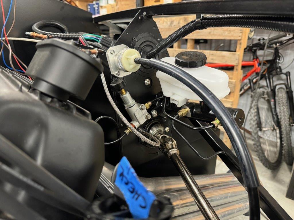
It was silly of me to think I could finish my brake lines without any rework. Thanks to Jeff Kleiner for pointing out that I flipped the brake lines going to the MC. Got that sorted out.
Engine plumbing
I didn’t make much progress with the plumbing as I was focused on building the new footbox. The heater hoses are roughed in but I don’t want to tighten the heat shrink clamps until I have the new footbox in place and riveted. I suspect I may need to pop out the blower box in order to access all the rivets. I could rivet from the underside but prefer not to see the backside of the rivets. The lower hose (Breeze) is in place and ready to be finished up.
Wiring
The primary power wiring is completed from the battery to the cutoff switch, including the starter feeds, grounds, etc. Basically I need to take it from the switch to behind the dash. My plan is to clean up the gauge wiring and figure out where the connectors will land behind the dash. Then I can better plan all of the dash wiring, relays and bus bar locations, etc.
I also wrapped up all of the engine wiring for the senders, coil, etc. Should be ready for first start once I land the rest of the dash wiring.
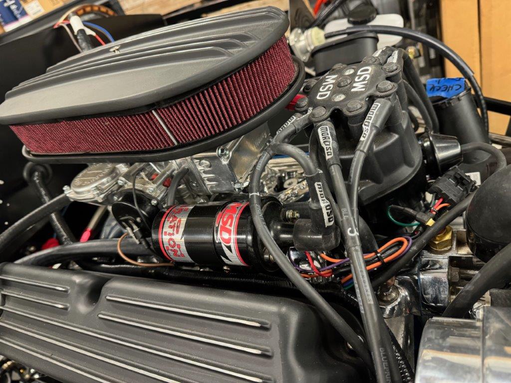
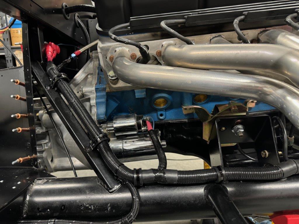
Fuel Plumbing
With the new footbox nailed down I was able to button up the fuel line routing to the engine. Done!
Next Week
I’ll spend time on the gauge and dash wiring this week. I expect to get the gauges rewired and hopefully rough in the dash wiring, sort out switch locations, etc. If I need a break from wiring I will recruit some help and bleed the brakes.
-
Senior Member

You say aluminum, I say aluminium Whatever way you say it, I reckon you have done a great job on the foot boxes! Nice work, my friend. Stand back and be proud.
BTW, did you powder coat the barbed tails for the heater hoses?
Cheers,
Nige
Mk.4 FFR supplied Right hand drive
Received 12/2012 completed 12/2019
Gen1 Coyote / TKO600 / IRS
Lots of mods to make compliant for Australian design rules
-
Member


Originally Posted by
Nigel Allen

You say aluminum, I say aluminium

Whatever way you say it, I reckon you have done a great job on the foot boxes! Nice work, my friend. Stand back and be proud.
BTW, did you powder coat the barbed tails for the heater hoses?
Cheers,
Nige
Hey Nige,
Regarding the heater hose connections, I sprayed them with a rattle can. Had I known I'd be making another trip to the powder coat guy I probably would have gone that route.
-
Member

More Wiring and My Extended Footbox is Installed!
I had a pretty productive week, with most time spent on the gauge cluster, dash, main wiring harness and my new, extended PS footbox.
Dash and Gauge Rewire
The gauge wiring was really rough when I purchased the car - lots of excess wire and many questionable connections. So, I ripped out all the wiring and pulled the gauges and cleaned up the rough edges of all the cutouts. In my opinion it’s much easier to start fresh than to try and sort out someone else's work - I guess that seems to be a guiding principle for this entire build.
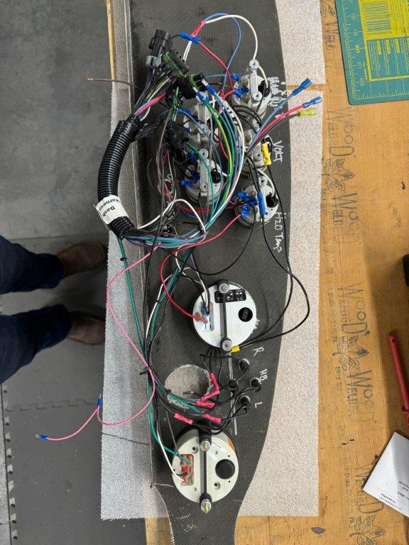
While I had everything apart I painted the backside of the carbon fiber dash to get a more consistent look on the front side. I was afraid of light bleeding through from the gauges or whatever. Maybe it would not have been an issue - Definitely won’t be an issue now.
I completely rewired the gauge cluster and dieted out the extra wiring and tidied everything up. Other than gauges, the dash will only contain the ignition and horn.
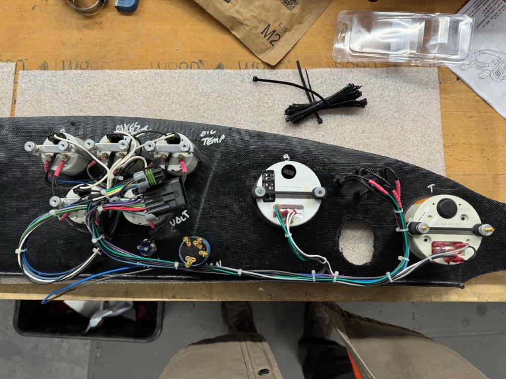
Behind the Dash Rewire
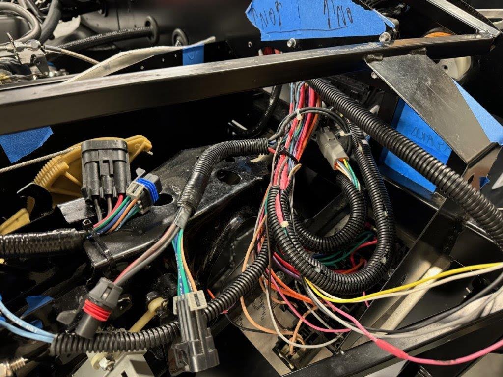
Once I had the dash cleaned up I mounted it back on the car so I would work out where all the wiring and connections would land. I made some adjustments to the locations of the dash connections to maximize the space behind the dash. I tweaked the other wiring harness connections as well - again, to maximize the available space behind the dash. I ended up removing the plugs from the engine harness and spliced the harnesses together. I left all the other harness plugs in place. I added a Deutsch plug for the extra wires heading to the rear of the car: Seat heaters, courtesy lights, reverse lights and the USB charger in the cubby.
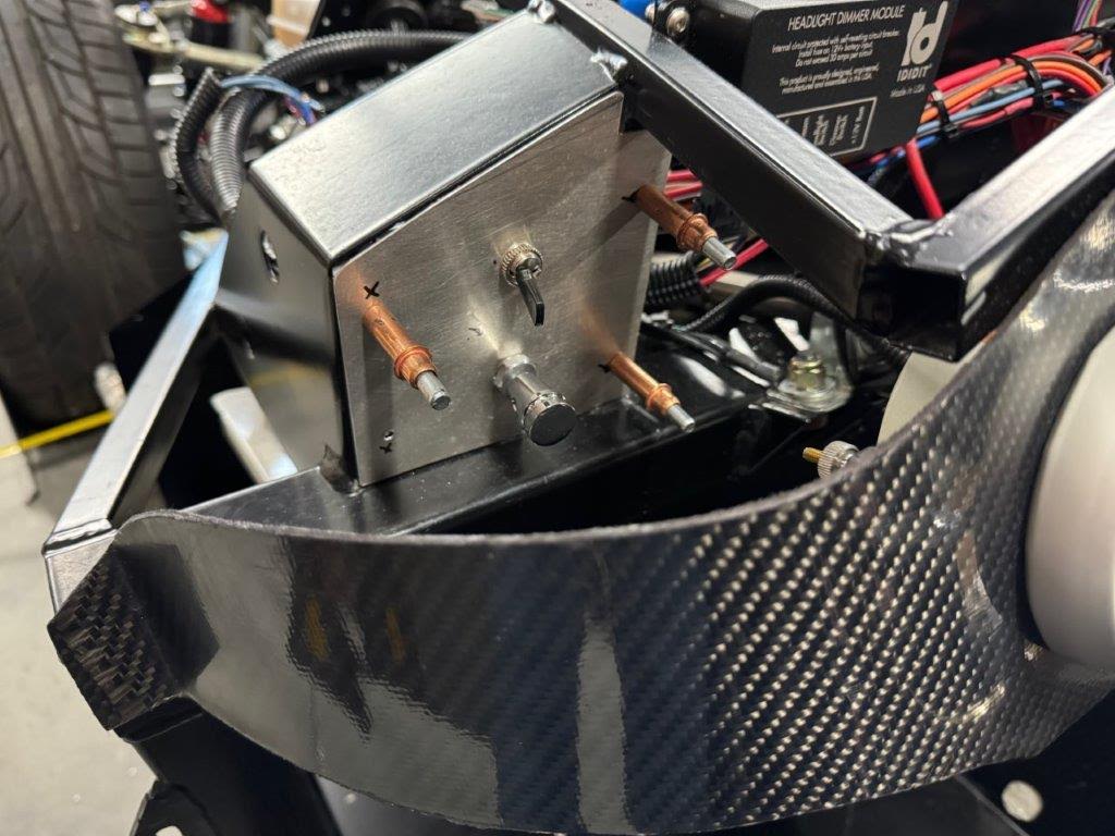
I plan to mount the headlight and flashers to the right of the steering wheel, just behind the dash. I’ll make a little panel and keep them hidden. This has the benefit of tidying up the clutter behind the gauges as the lighting harness will shoot to the left and I can hand run the flashers and blinkers off the hot rod harness. I know a lot of folks cut that out but I have found it useful on my coupe and also this build. I plan to put the heater control, wipers and USB/cigarette lighter stuff on a panel under the center of the dash. The seat heater controls will be mounted to the seats as I did with my coupe.
The Russ Thompson signal and headlight toggle has been connected up via Deutsch connector and tied into the main harness. Again, it falls back to the hot rod leg of the main harness. I also went with the Ididit Headlight relay again. Super simple and it has proven to be reliable.
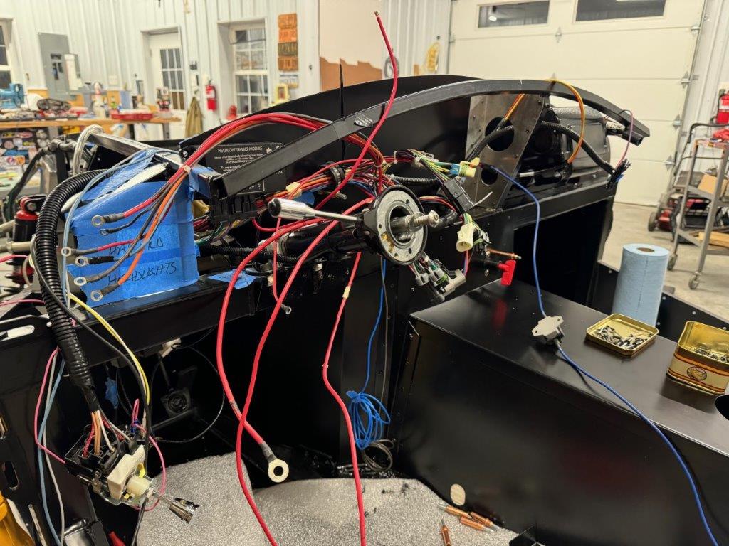
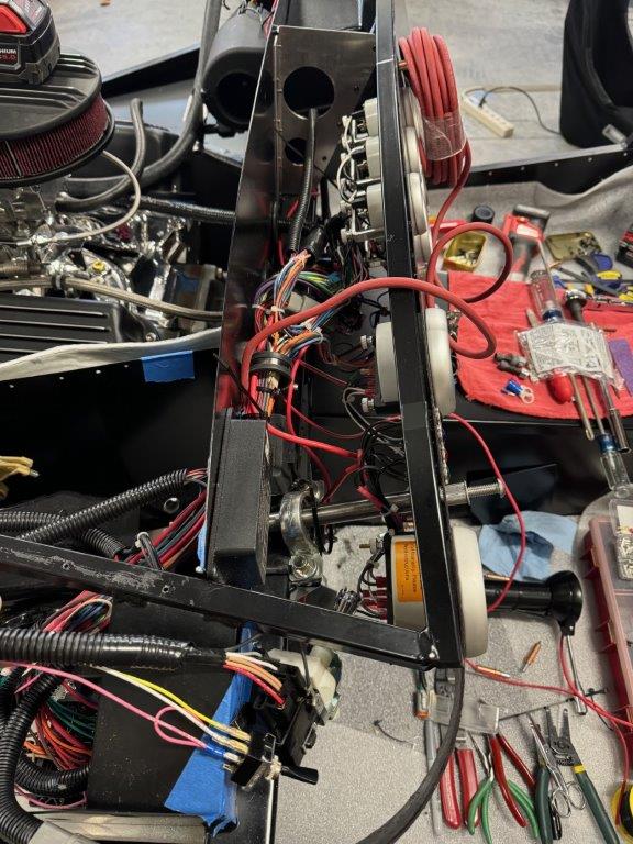
Wiring QA and Validation
With the wiring together I started the QA process before applying power to the harness. Checked positive leads for shorts to ground and everything came back clean. Then tested all other connections for shorts back to ground… basically checking for continuity to ground and trying to avoid any nasty shorts. And then just checked continuity from here to there… All good.,
To take things a bit further, I used my 12v power supply and applied power to each “segment” of the harness. I tested headlights, switches, turn signals, flashers, brakes, clutch safety, etc. in order to validate all the connections that had been made. In order to simplify troubleshooting and reduce any damage I unplugged whatever harnesses I could before testing the core harness. All good.
More Powder Coating
The new PS footbox and a few other bits were dropped off for powder coating and came back. They gave me a break on the price given that they lost my footbox floor from my last batch. The new footbox is installed, sans the outside bit… leaving it off for now.
Also took the opportunity to use my templates in order to cut out a few pieces of insulation for the footbox. My focus was the area around the headers, so the inside and front of the footbox were insulated. I also need to do the driver side as well as the trans tunnel. I ended up using DEI black dimpled aluminum and fiberglass. With the insulation in place the corner is quite close to the headers. I’ve got some 500 degree tape on order. Hopefully that holds up.
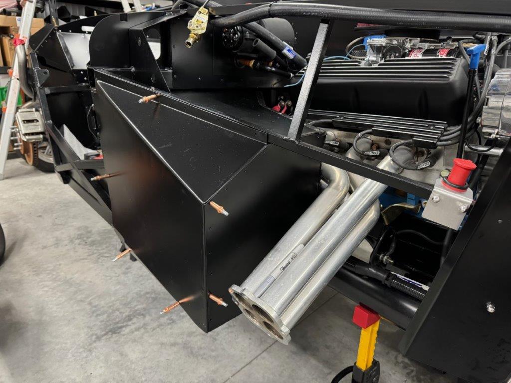
Mystery Panels
I’m not really sure where these two panels are supposed to go. Can anyone help me out here?
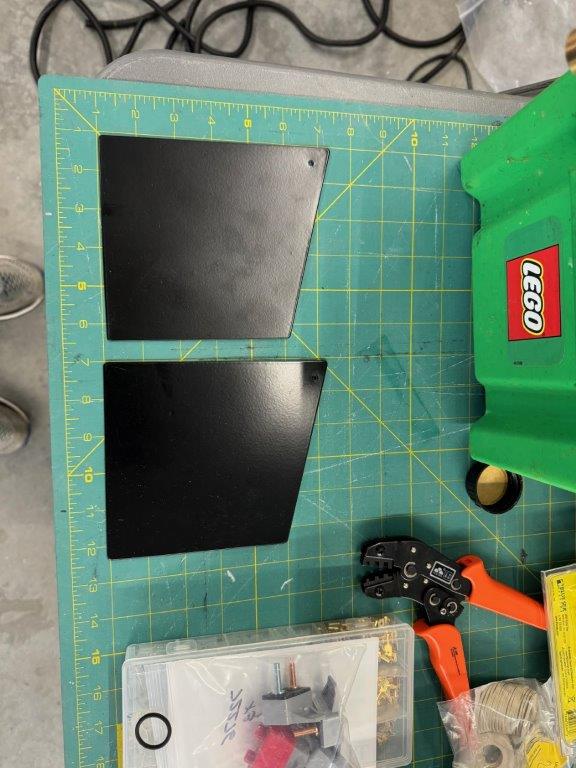
UPDATE 11/18/2024
Well I didn't get any confirmation on the purpose of these panels. Being a basket case, perhaps that were unrelated to this build at all and just found their way into the piles of car parts I gather from the sellers sheds. Or maybe is was something for very early Mk3 kits and I just haven't figured it out yet.
On Deck
Over the next week I will get the brakes bled and finalize the primary power feed from the transfer switch to the main harness; also need to get the positive bus bar in place along with the fuse on the alternator feed. I hope to get my center switch panel (and dash support) section built. With this done I can get some relays and breakers mounted. Might wrap up the engine plumbing.
Last edited by TTimmy; 11-18-2024 at 11:30 AM.
Reason: Update
-
Member

-
Senior Member

This is one of my all time favorite build threads. I am honestly a little jealous. I may look for a rehab on my next build. Great job, I am enjoying following along.
-
Post Thanks / Like - 1 Thanks, 0 Likes
-
Member

The Great Restart!
The theme of the week has been getting the basket case ready for its first restart and perhaps some go carting.
Side pipes
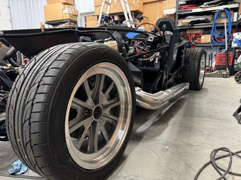
Side pipes are installed! Fabbed up a pair of hangers out of heavy gauge wire that hang from the door hinge mount. Lines up perfectly with the mount point on the pipes!
Alignment
I did a quick alignment in case the weather might be agreeable enough for go carting at some point. Focused on ride height, camber and toe in. I need to come back and do caster. I’m considering some proper turn plates so I might hold out until I make a decision on buying.
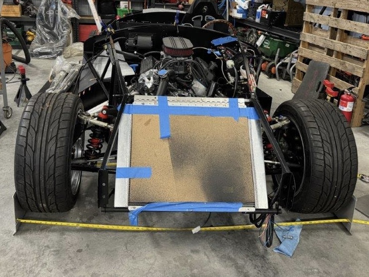
Here are the steps I followed for my coupe after purchasing some basic alignment gear for camber and caster
- Set tire pressure all around
- Unload the sway bars (no sway bars on the roadster)
- Set ride height on level surface
- Adjust rear wheels (if applicable - Gen 3 IRS on my coupe, three link on my roadster) to be centered and square to the frame using jack stands and string
- Adjust rear camber and then toe (again, if applicable). This is an iterative process as each adjustment affects the others.
- Adjust front steering wheel/rack to approximate "center"
- Adjust front camber
- Adjust front caster - power steering settings. Like the rear, each adjustment affects the others so I keep adjusting camber and caster and toe and things will converge on the proper settings.
- Adjust front toe
- Fine tune front toe (distribute left/right) to keep steering wheel centered
- Reconnect the sway bars
Plumbing
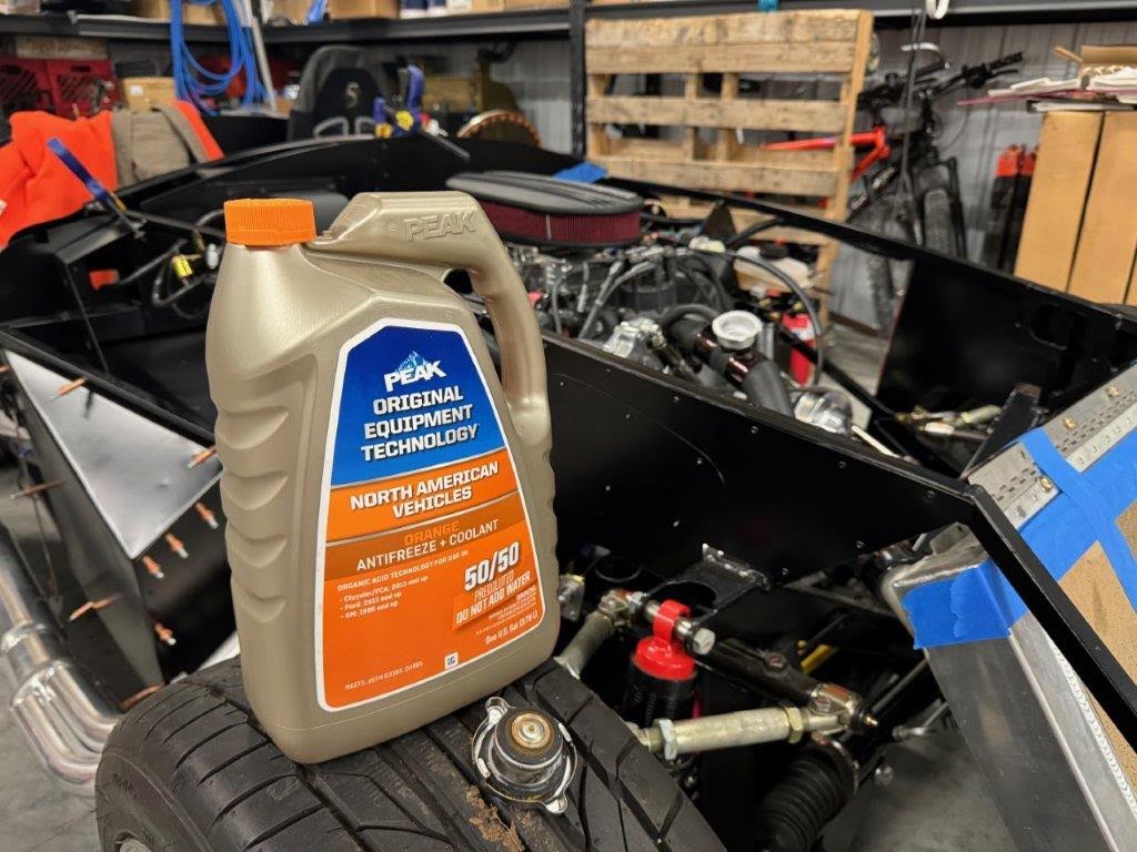
Finally got my plumbing buttoned up! I had been waiting on the proper sized PowerGrip fasteners which are tough to buy from Amazon. Seems they don’t have them all properly listed by size or PN. Thus I was frequently getting the wrong size. I found another source - seems like more of an independent option anyway so happy to send them my business.
With that done, I added some coolant to the system.
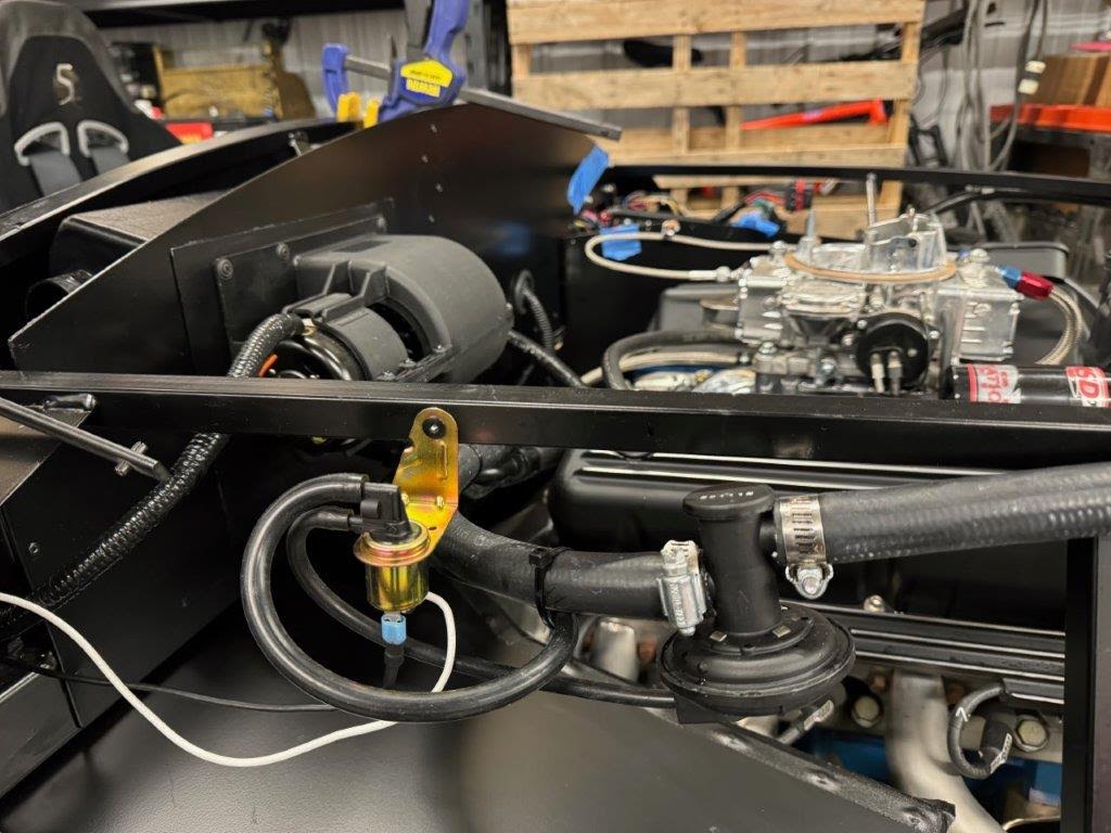
Heater
The new heater vacuum control valve is working as expected. Will need to dress in the wiring for this entire area at some point, including wipers, control valve and the blower.
Electric
I added the headlight controls and flasher in the little pocket behind the far left side of the dash. I also fixed my L/R turn indicator mixup. Signals are all good now and the hazards still work.
The Great Restart!
Frankenstein breathes again… Back to life!
The fuel system held pressure and the other PFC items are good. So fire it up I did!
Needed to give the power steering a little love after starting it up. Seems to be holding up now.
Once the engine was getting up to temp, I spent a little time troubleshooting my fan… sensor, fuses, relays and the like. Seems the harness to the front needs to be connected up for it to function. I don’t recall having that problem on my coupe, but something to keep in mind for my Mk5 build.
-
Member

Going Go-Carting!
Go Carting
I hoped to take the cobra for a spin before leaving but the weather had turned quite foul and wet. Thus, no test drive before thanksgiving. Upon returning I did get it out for a test drive. While it was now dry, winter had clearly arrived. So, I took it out in 35-degree weather. It gets rather cold at about 40 mph.
My neighbor came over to provide support - just in case technical assistance or a tow became necessary. He has helped out more than once on both builds. No help was needed this time, but it was nice to share the moment with someone. My observations at this point are as follows:
- The external fuel pump is very loud. Likely this will be much less of an issue when the car is “really” being driven. I am used to in-tank units.
- The Blueprint supplied power steering pump is pretty loud when turning. PS seems to function as expected. I’m not sure if there might be an issue with the pump
- Still have a small leak somewhere on the PS pump. Everything is tight. I did not pull off the AN adapter when I rebuilt things - wondering if the prior owner might have forgotten the o-ring.
- Need to tackle a small leak on the right front brake line.
- The stock FFR brakes are fantastic with the Cobra master cylinder. They perform much better than the stock FFR brakes on my coupe. I need to double check everything on the coupe - clearly it should perform better.
- All the electrical bits that are connected seem to work: speedo, tack, water, oil, fan, etc.
All I have for evidence is a bit of ring camera footage. It doesn’t do the sound justice, but most of you know the sound of a nice 302.
https://youtu.be/wxVKQb5DJbU
The dilemma now is trying to decide when to pump the brakes on this project and start working on the coupe bodywork. Now that they are salting the roads I don’t expect to be cruising for a while.
Next Steps
This week I am prepping to apply Lizard Skin heat and sound insulation. So I will be scuffing the interior and trunk; and then making off everything. Wondering how the Lizard Skin option will stack up against the Dynamat type option in terms of effort and effectiveness… Stay tuned.
-
Member

! Lizard skin !
I have been working on the car intermittently over the holidays as I weave in time with family and friends. The focus of this post will be my first Lizard Skin application as well as sorting out a couple minor issues left by the prior builder.
Lizard Skin Heat and Sound Insulation
I went into the lizard skin project wondering how it would compare to Dynamat and similar solutions. My assessment at this stage, for the roadster anyway, is that they probably require a similar amount of overall effort. I am not sure which I prefer, though I will say that the Lizard Skin is much more satisfying to look at! I know, all gets covered up at some point, but I do take satisfaction in its appearance, if it is only a fleeting feeling.
The benefits of the Dynamat is that no prep work is required in terms of taping off the car (and shop)... you can just jump right in and get to work applying the material. You also have the benefit of doing it incrementally as the project progresses. E.g. you can insulate the footbox today and deal with the trunk in the future. Another consideration is ambient temperature. Dynamat doesn’t really care about the temperature when it’s applied. The temp window for Lizard Skin is pretty narrow.
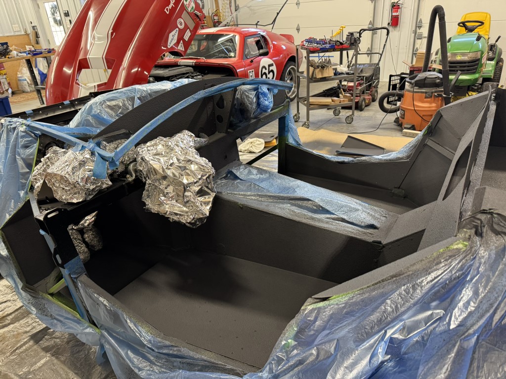
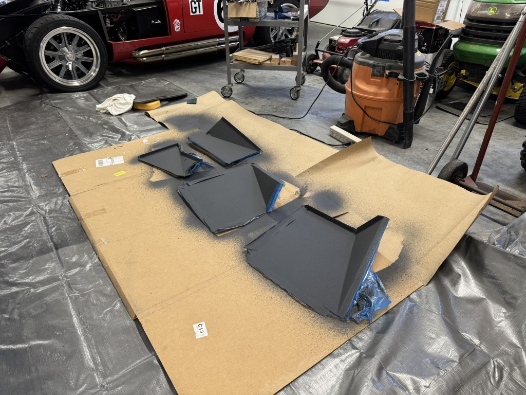
Lizard Skin application really requires you to do the entire project at once. Otherwise, there will be a lot of wasted/duplicate prep effort. Most of the time is spent prepping the car; the application of the product goes quite quickly. As far as prep, you will need to remove stuff you don’t want sprayed or cover it up. I mostly used plastic sheeting with masking tape attached to it for masking off the bulk of the car (I have the benefit of having an Eastwood store and a PPG dealer nearby). For the oddly shaped bits I used aluminum foil… footboxes, electrical, etc. It works really well. I left the footboxes open and masked off the pieces that were not yet attached.
A day or so ahead of product application I cranked up the heater in the shop so that everything got warmed up. I threw down a couple tarps on the ground and got to it. If you have not used this product before, it is basically like spraying pancake batter out of a paint gun. In addition to the masking and tarps I also relied on a cardboard shield to keep the overspay contained.
I estimate that the prep was probably 90-95% of the effort. Actual product application goes quite quickly. If you want a more detailed explanation of the entire process, I suggest you track down EdwardB's post on this topic. He covers it quite well!
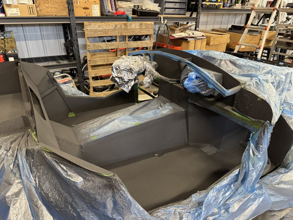
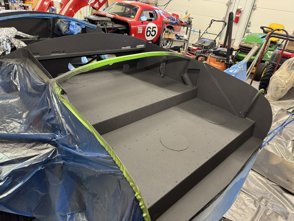
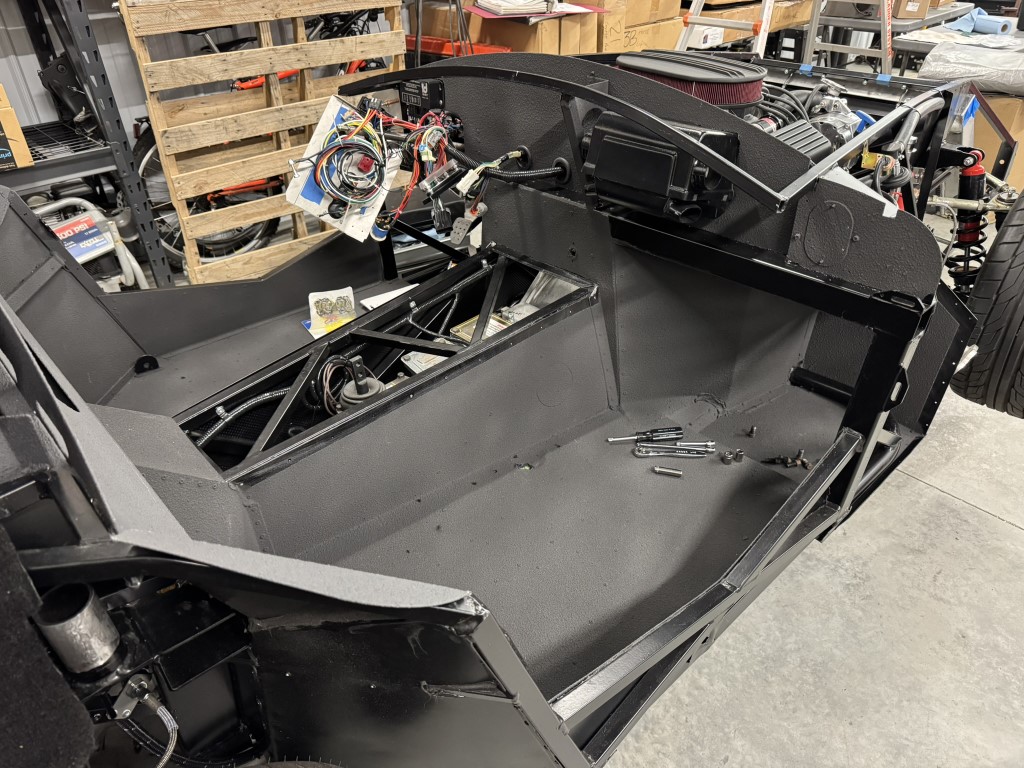
Header Bolts - Stainless Upgrade
I sorted out what I hope are the last of the issues left behind by the prior owner. The header bolts were all rusting. This after no road use and only being in place for a couple years. I chose to swap them out with some ARP stainless steel bolts. I know it probably doesn’t matter, but it matters to me. Removing the old bolts was pretty easy as most of the hard-to-reach bolts had not been tightened. The new bolts had a smaller head so that provided a bit more room to work around the headers.
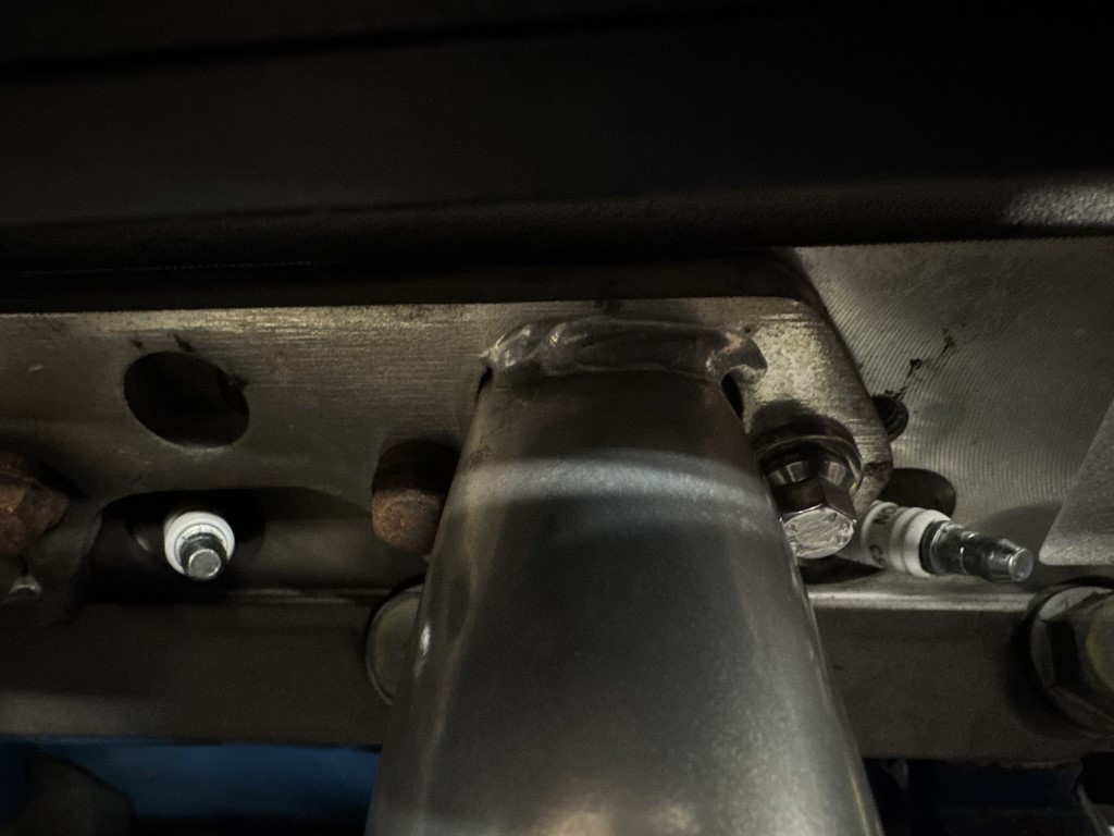
Plug wires
When I originally went to inspect the car I noticed that several of the plug wires were neatly wrapped with a bit of electrical tape. Again, this was a new BluePrint 306. I figured that meant that some unfortunate surprise was waiting for me. And it was. When I finally removed the tape, I found that several of the wires were quite chewed up. Perhaps in the literal sense, it appeared that something had been gnawing on them.
Whatever the case, I need a couple new wires. It was cheaper and easier to just get a full set versus buying the material to make new ones. Standard SBF sets don’t work with the Blueprint wire management. They are way too short. Blueprint sells plug wire sets, but only in blue. I wanted black. I found the best option was a BBC “under header” set of plugs. They provide the necessary reach to use the Blueprint plug management dohicky. The Moroso wires I used all came labeled for each cylinder. Obviously that no longer applies if you are using BBC wires. The labels are heat shrunk in place and were easily removed.
Probably would have been easier to just transition to the SBF wires and change out my plug wire management. But why do things the easy way.
Oh, and glad I changed out the wires as this led me to a broken spark plug.
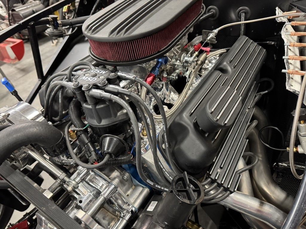
Sound Track
Not sure if anyone cares, but I do care. I listen to a lot of music in the shop. Sometimes it’s completely random. For this spell I was listening to a lot of Alman Brothers. I started with the really old stuff and worked forward in time, ending with a lot of live shows.
On Deck
My next updates will cover carpets, cubbies and who knows what else. I am also debating whether to start a thread on my Daytona body work project which has now started. Not sure if that is of interest to anybody. I have never done bodywork so maybe I am not the right guy.
-
Member

All about the Carpet
All about the Carpet
I am continuing work on the interior, carpet to be specific. As one thing tends to affect another this also meant I needed to work out my Breeze seat mounts as well as the heel pad that I will use next to the accelerator.
Mk3 or Mk4 Carpet Set?
My kit came with an interior carpet set plus an additional ~4 square yards of material. I suspect the carpet set is for a mk4 as a few of the pieces did not really seem to fit properly. The problematic bits were the rear/outside segments that sit between the seat and the rear tire. On my car this piece of aluminum attaches outside the frame rather than inside. Each side is made up of two pieces of aluminum. The carpet is a single piece for each side. Easy enough to just cut and trim.
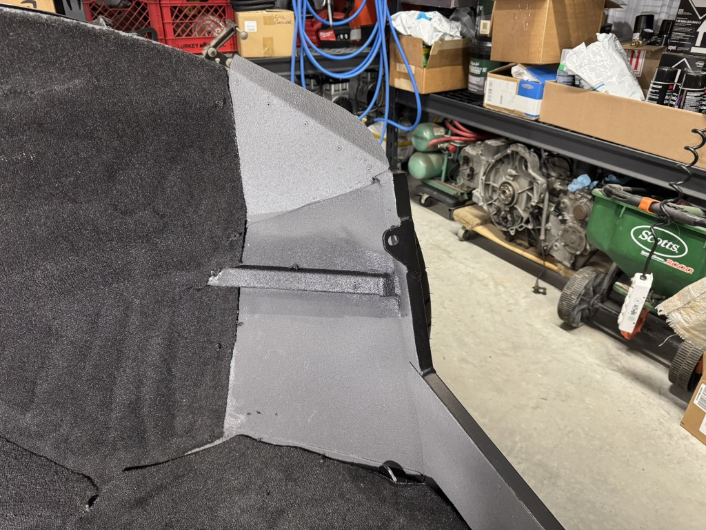
I also had to accommodate the larger PS footbox that I built. I used the extra carpet for the footbox, trunk floors and trunk sides.
For the passenger compartment floors I trimmed out the section occupied by the Breeze seat mount. I know some folks install the seat mounts over the carpet or carpet over the seat mounts. I didn’t want the compressed carpet working itself into the seat mounting solution at all. It was pretty straightforward to trim this out and get the carpet applied.
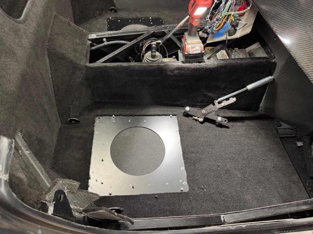
Cubby
For the cubby I went ahead and carpeted the floor. For the side I used some felt I had left over from the coupe. That solved a couple problems: got rid of the last of the felt, conserved some of the carpet and because it is a much thinner material it left more room in the cubby.
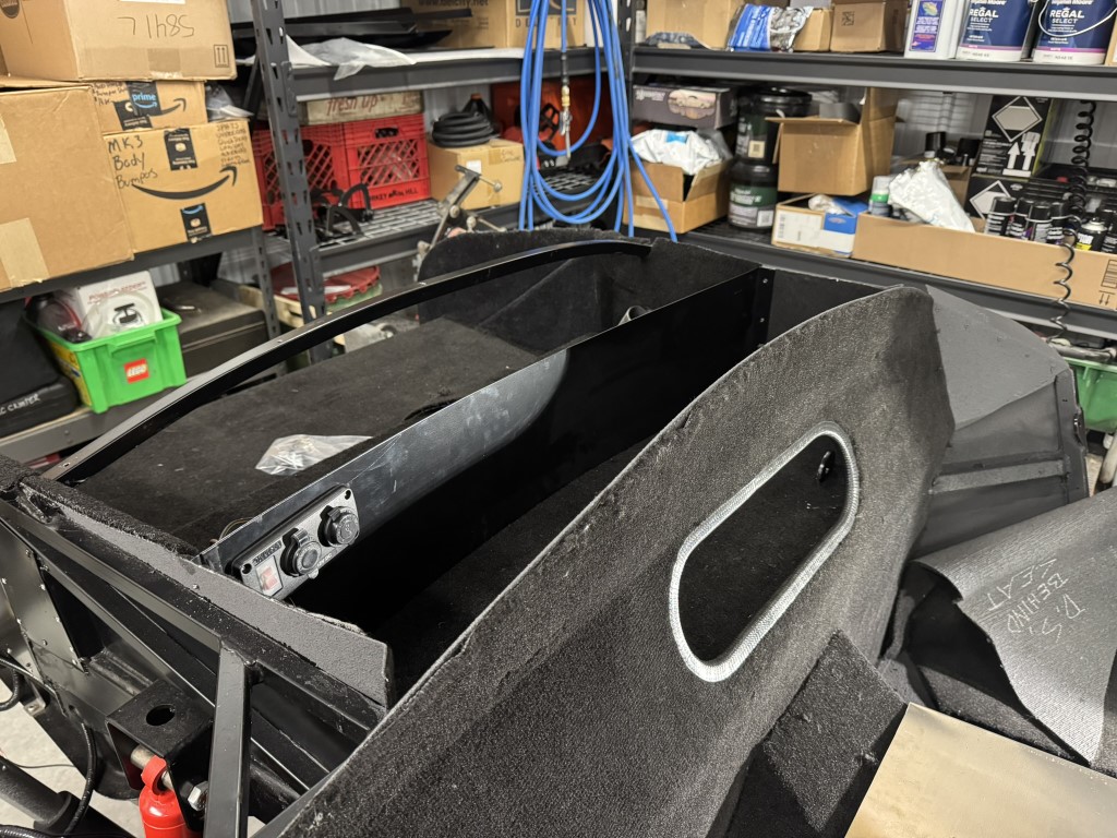
Accelerator Area Heel Pad
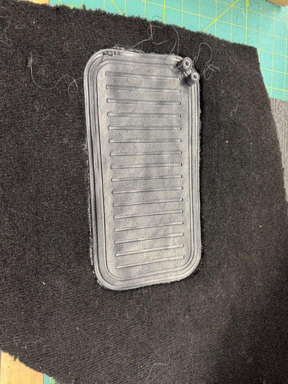
The only carpet remaining is the outside door bits as well as the firewall piece. The door pieces need to happen later from what I understand. The firewall piece is on my work bench as it needs a bit of special attention. I am in the process of affixing a “plastic” (Vinyl?) heel pad to the right of where my foot will contact the accelerator. This will provide a bit more clearance, eliminate carpet wear in this area and reduce interference/friction where my foot will inevitably rest on the side.
As you all know, nothing is easy. To maximize clearance and improve the application of the heel pad I used a beard trimmer to shave down the carpet in this area. I used 3M 90 adhesive and applied the pad. I weighed it down with a battery to get a good tight fit. However, the next day when I pulled the battery off I found that the heel pad material had kind of softened and expanded - as though there was an incompatibility with the adhesive. The glue was still quite sticky. It did not set properly. So off it came. Later that day I noticed that the heel pad had stiffened up again so I went ahead and gave it another try. 36 hours later and it seems to be holding up. Once I am confident in the application I will try my hand at sewing in the edges and get the whole carpet segment glued in place. So very close to being done with carpet, for the time being.
Fuel System Access
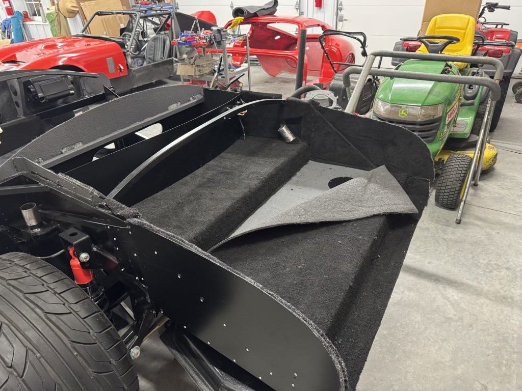
Given the issues I had with my coupe fuel system I decided early on that access to the sender and pump area is required. (One failed fuel pump, one failed hanger and one failed sender). I cut holes in the aluminum a while back and made up some covers. For the carpet I decided to cut the trunk floor into two sections: upper/forward and rear/lower. For the upper trunk I glued down the entire piece. For the rear piece I glued down the rear most section of the trunk and left the forward part unsecured. This provides the necessary access. I am not concerned about the carpet moving around.
Sound track
Always some random stuff, but mostly Dire Straits, Mark Knopfler and whoever Mark has played with.
-
Senior Member

I had that issue with some I had an upholstery person due for me, which they were sewed as well. I suspected the cure time due to lack of air once it got put on, but is did finally stick.
-
Member

Seat Heater Install
Seat Heater Install
I liked what I did with the coupe so much that I did the exact same thing for the roadster.
I run power to the seats and install the entire heater switch assembly, relay, etc. into the seat along with the heater pads. I locate the switch on the inside (trans tunnel side) of each seat. I ran the seats off the heater circuit (I think) or maybe I put in a dedicated breaker… can’t remember which way I went without checking my notes. Whatever the case, you will need adequate power to the seats.
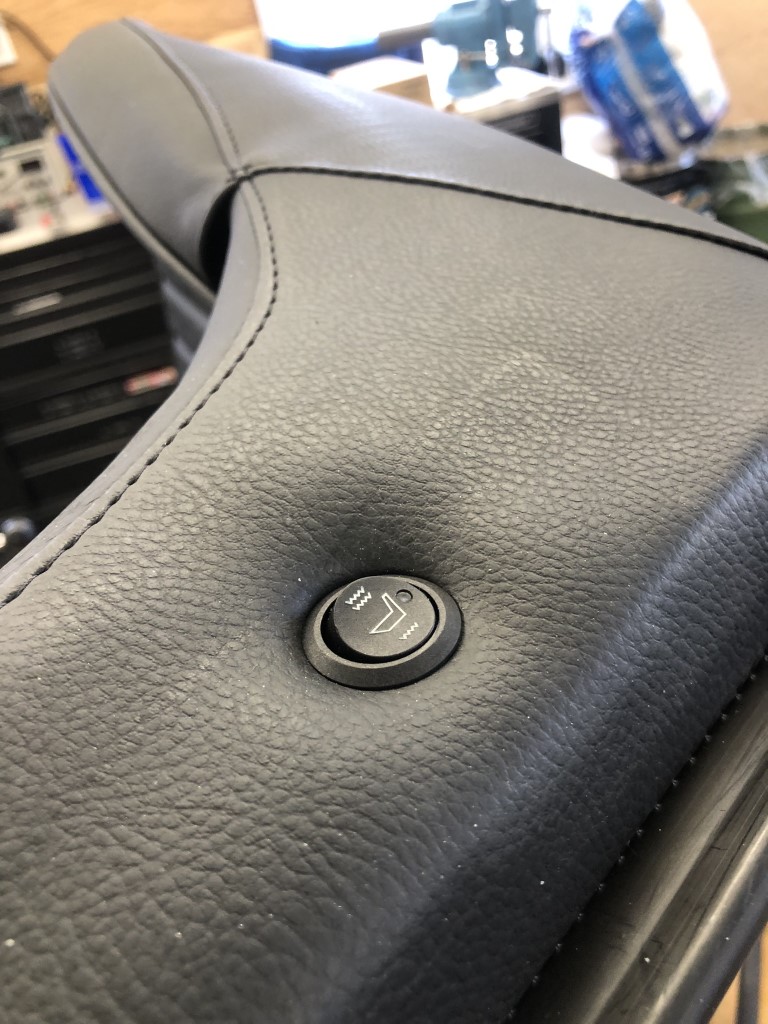
I started with the Dorman PN: 628-040 seat heater pads. If you shop around you can find them for about $65
I start by making up a couple small backer brackets that sit behind the leather and attach to the seat frame. You need to find the right location between the seat frame pieces as two metal frame elements come together in this area. It was a bit tricky to get the size of the bracket hole just right to accommodate the switch and also the leather that needed to be tucked in alongside it.
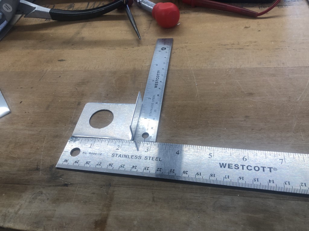
Once I found the right location, I marked the area that needed to be cut to accommodate the switch. I did not secure the bracket to the seat frame until after the switch was installed as I needed to make some minor adjustments to the position, and it helps when trying to fish the wire through the leather, cushion and frame.
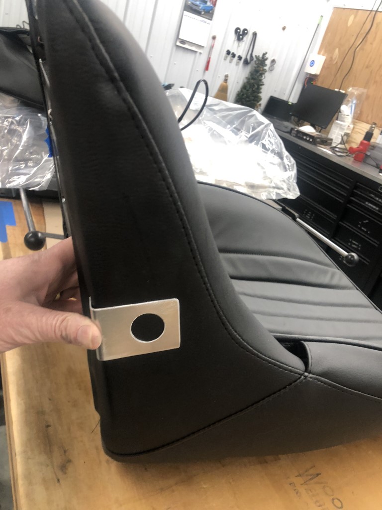
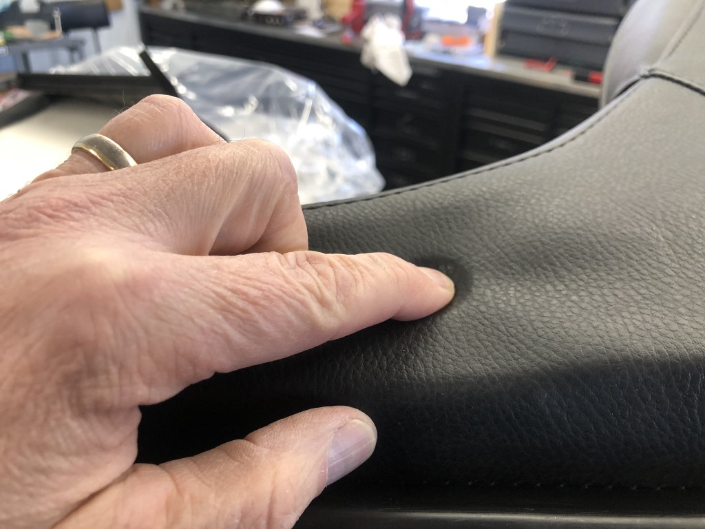
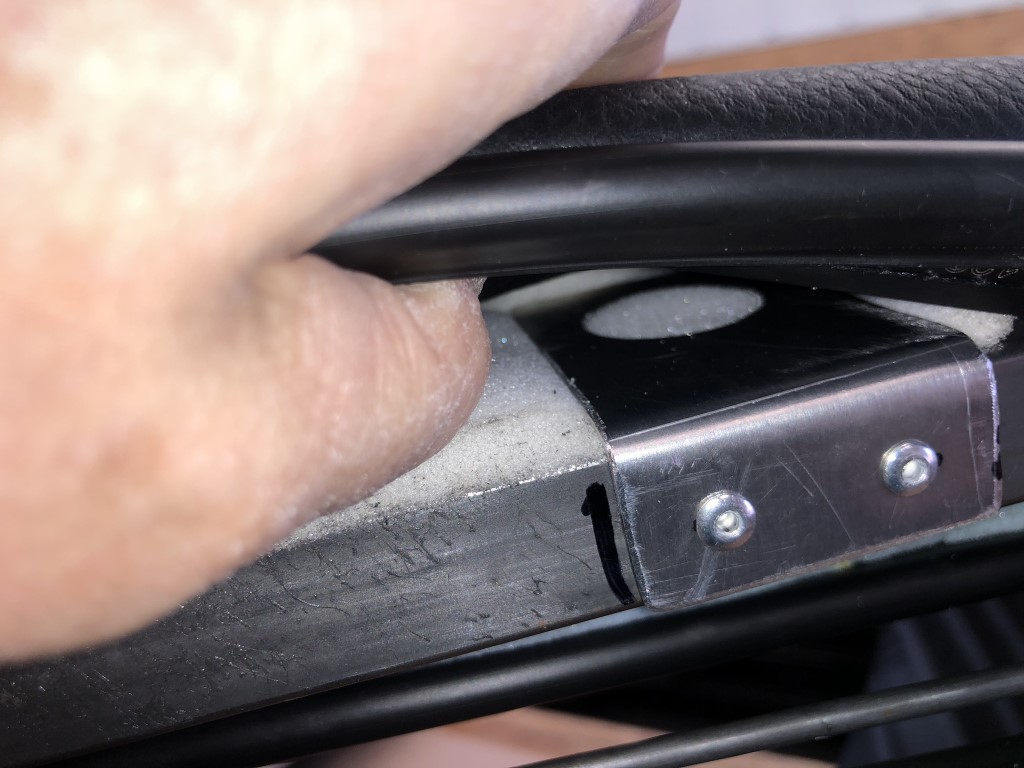
There are two layers of cushion in that area; one thick and one thin. The thin layer is on the outside and you will want to play around with it relative to the bracket. It is easier to get the switch installed with the cushion behind the bracket; however, you can kind of notice the bracket if you look closely. If you put the cushion outside the bracket, it is unnoticeable. Frankly, it will be unnoticeable either way as that location is relatively hidden. Anyway, this is something to consider as you need to make a decision.
Once the switch was in a good position I riveted the bracket in place.
I installed the seat heater pads to both the back and bottom of the seat per the instructions. There was plenty of room to work on the back; but you are working blind as you can’t really see behind the seat/leather. Removed the adhesive backing and secured the heater pads to the seat cushion.
For the bottom it is necessary to pull off one side of the leather from the foam. It came off cleanly for all the seats that I have done. Again, install the heater pad adhesive to the foam. I used 3M 90 adhesive to secure the leather to the foam. I held it in place with a few clamps while it set.
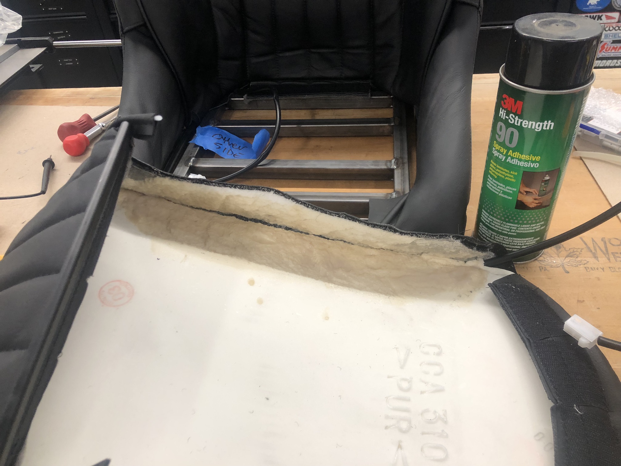
The heater comes with a complete wiring harness with enough length to install the switches and power feed in the dash. I cut out a large section of the harness so that I could easily tuck it between the seat frame. It fits in there nicely.
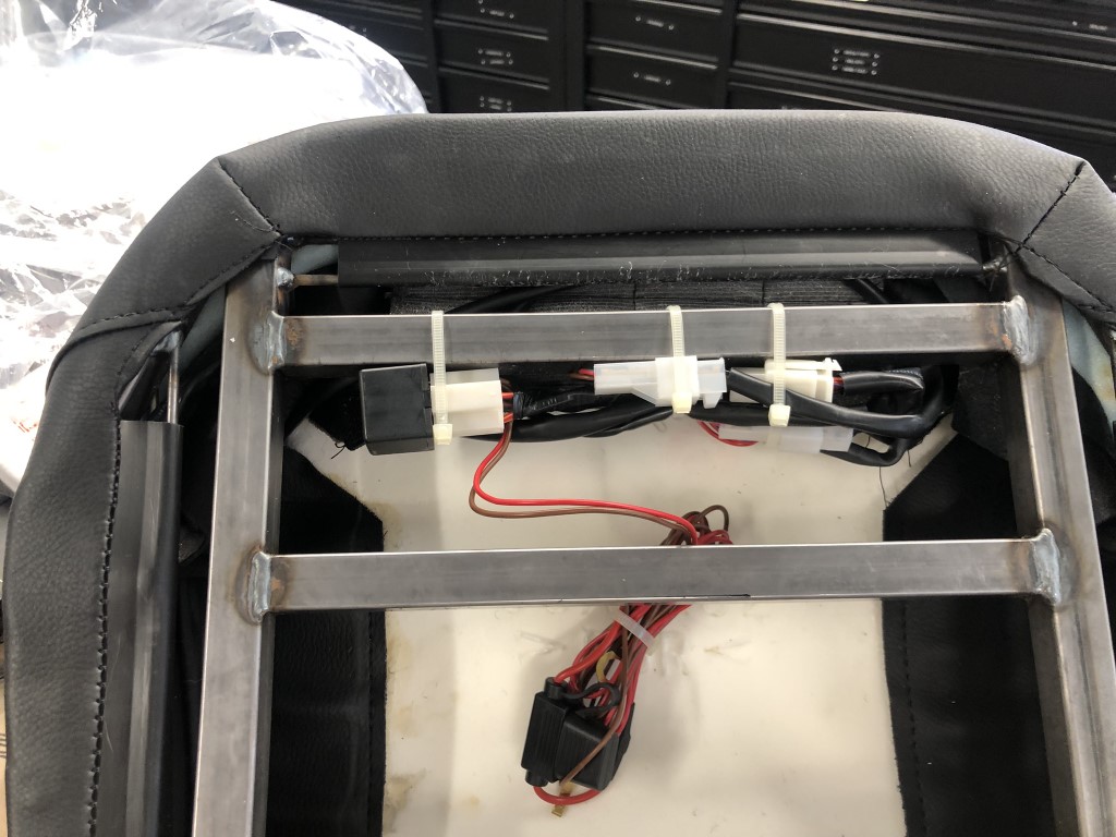
I have added a lot more files to my gallery, but the forum limits me to seven photos per post. Feel free to check the gallery for more images. https://thefactoryfiveforum.com/album.php?albumid=2537
Last edited by TTimmy; Yesterday at 08:51 PM.
Reason: Edit


 Thanks:
  Likes:


 Reply With Quote


 Whatever way you say it, I reckon you have done a great job on the foot boxes! Nice work, my friend. Stand back and be proud.
