-
10-06-2024, 05:53 PM
#201
Senior Member

A lot of great detail in here. Much appreciated update.
-
Post Thanks / Like - 0 Thanks, 1 Likes
-
10-06-2024, 08:42 PM
#202
Senior Member


Originally Posted by
dbo_texas

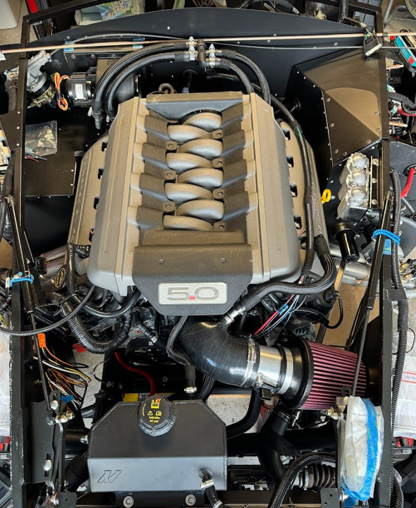
And finally, here a pic w/ the engine cover installed:
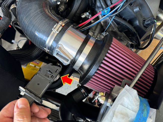
Forgot to post this pic showing the direction/orientation of the MAF sensor. This is the sensor that gets removed from the stock intake/filter box that comes with the crate motor. I have it positioned with the rounded edge toward the bend in the intake elbow, so that the air gets forced into the sensor. If this is incorrect, somebody let me know! It's easy enough to flip - you just have to flip around the Treadstone MAF tube.
Darryl [dbo_texas]
MKIV #9644 (build thread) (Index)
MK4 Complete Kit | Gen2 crate Coyote | Tremec T56, 3.55 IRS | power steering | hydroboost | dual roll bars | FFR carbon fiber dash | 18" Halibrands + Wilwoods | RT drop trunk kit & turn signal | front battery mount | saddle leather Intatrim Stoneleigh seats + interior accents
-
10-14-2024, 09:35 AM
#203
Senior Member
I found a 3/8 SAE Quick Disconnect cap to put on the 3/8 port on the outside elbow of the intake. Looks a little cleaner vs. the rubber cap + clamp option. I thought the evap purge vent above the throttle body was also 3/8 but it's slightly larger....maybe 7/16 so I kept that one capped with a clamp. Surprisingly there don't appear to be many places that make these SAE blanking caps, but this is where I got it from if others are interested:
https://www.anhosefittings.com/racef...nking-cap.html

Darryl [dbo_texas]
MKIV #9644 (build thread) (Index)
MK4 Complete Kit | Gen2 crate Coyote | Tremec T56, 3.55 IRS | power steering | hydroboost | dual roll bars | FFR carbon fiber dash | 18" Halibrands + Wilwoods | RT drop trunk kit & turn signal | front battery mount | saddle leather Intatrim Stoneleigh seats + interior accents
-
11-24-2024, 07:29 PM
#204
Senior Member
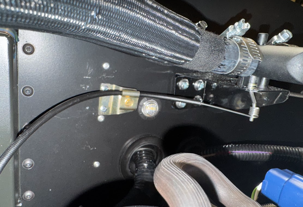
Heater bypass valve cable install
Haven't had a chance to work on the car for about 2 months. I'm planning to take this week off for Thanksgiving and get some good hours in. Tonight I decided to mount the actuator cable for the heater bypass valve. This has been bothering me for a while because I wasn't sure how I was going to do it. Turned out to be pretty simple. I used the bypass valve provided with the kit from FFR and cut the end off which has the screw clamp. Then I just riveted this to the firewall to secure the cable jacket. Tested and seems to work fine.
One question - what's the best way to secure the cable end onto the post? It can slip up or down (and fall off) fairly easily at the moment. Seems like one good bump will knock it off. I thought about using some JB Weld to fix a small washer just before the bend - that would take care of it moving up. I suppose I could do the same on the bottom after installing the cable but that would make servicing it a pain.
Darryl [dbo_texas]
MKIV #9644 (build thread) (Index)
MK4 Complete Kit | Gen2 crate Coyote | Tremec T56, 3.55 IRS | power steering | hydroboost | dual roll bars | FFR carbon fiber dash | 18" Halibrands + Wilwoods | RT drop trunk kit & turn signal | front battery mount | saddle leather Intatrim Stoneleigh seats + interior accents
-
12-01-2024, 07:25 PM
#205
Senior Member
-
12-23-2024, 10:37 PM
#206
Senior Member
HELP ME OUT - bolt size for Coyote mini-starter motor?
I have a complete setup from Forte - Gen2 Coyote + T56 + Quick Time RM-8080 bellhousing. I'm working on all things electrical, hoping to finish it during the holiday break and realized I don't have the bolts for the starter motor. I've tried a bunch of different bolt sizes and thread pitches, and nothing seems to work. I've tried 3/8x16, 5/16x18, 5/16x24, M8x1.25, and M7x1. The 5/16/18 seems to start threading into the bellhousing but stops pretty quick. The M7x1 actually goes in a little further before it stops. So now I'm thinking maybe it is an M8x1 fine pitch bolt? Weird size if that's it.... Anybody know what is the correct bolt thread size, thread pitch, and length for the mini-starter motor that Forte includes with the Coyote setup? The starter seems to be the stock Ford OEM starter motor for Mustangs as far as I can tell.
I'll give Forte a call after the holidays but was hoping to work on it sooner.
Darryl [dbo_texas]
MKIV #9644 (build thread) (Index)
MK4 Complete Kit | Gen2 crate Coyote | Tremec T56, 3.55 IRS | power steering | hydroboost | dual roll bars | FFR carbon fiber dash | 18" Halibrands + Wilwoods | RT drop trunk kit & turn signal | front battery mount | saddle leather Intatrim Stoneleigh seats + interior accents
-
12-24-2024, 07:11 AM
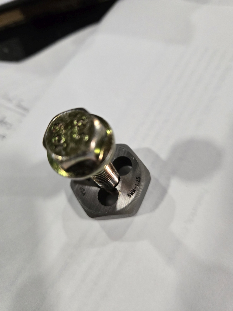
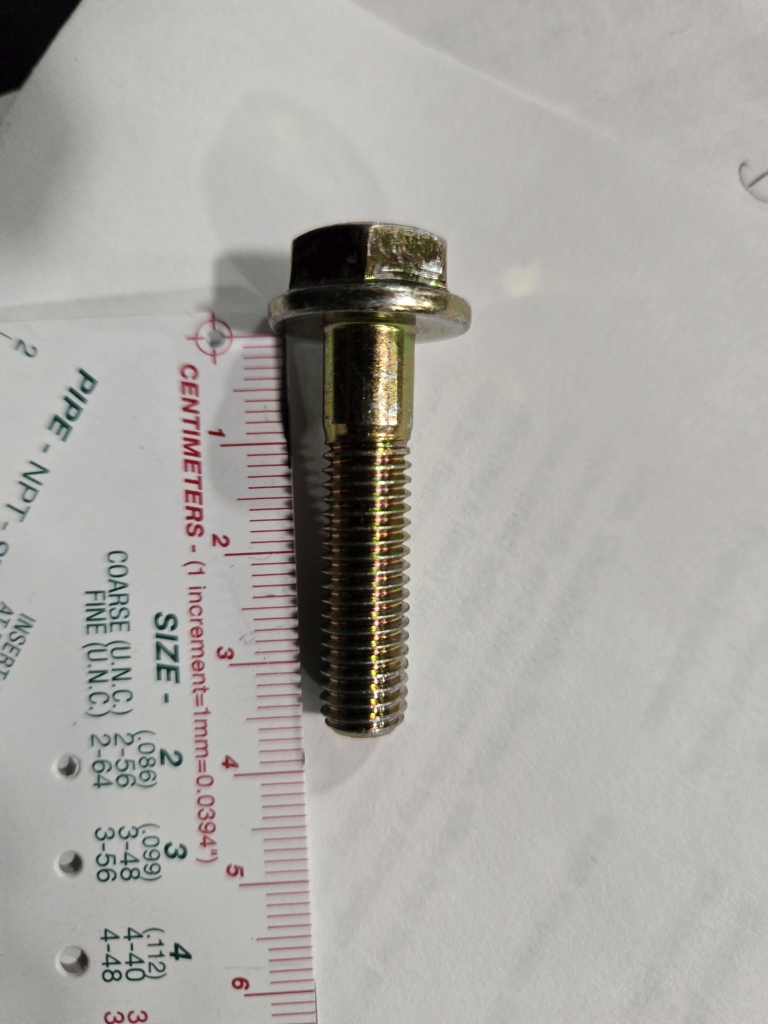
#207
I just put my coyote in a couple days ago. I was able to get to one of the bolts out and take some pictures for you. You're mileage may very with my hardware know how but I tried to give the detail in the pictures you need. Seems to me like 35mm long, m8x1.25, with a 13mm flange head. I tried to upload the photos from my phone but they are SUPER huge. I'll add the photos to this post when I get back to the house and I can edit the sizes on my computer. It'll probably be a few hours as I'm just starting my morning in the shop. Trying to get some things done before the kids wake up.
I was looking at the coyote install instructions and on page 3 they have this part number for the starter bolts W500310.S438 which does say m8 35 long.
It says 1.25 on the die if you can't read it in the picture.
Last edited by topherchrisb; 12-24-2024 at 11:30 AM.
MK4 #10255 project: "Mako"
Coyote Gen 3, TKX, IRS, Wilwood brakes, power steering
Order date: 6/24/21, Received date: 1/12/22, First Gocart date: 1/1/25, Registration date: TBD
Build thread
-
Post Thanks / Like - 1 Thanks, 1 Likes
-
12-24-2024, 09:42 PM
#208
Senior Member
Originally Posted by
topherchrisb
I just put my coyote in a couple days ago. I was able to get to one of the bolts out and take some pictures for you. You're mileage may very with my hardware know how but I tried to give the detail in the pictures you need. Seems to me like 35mm long, m8x1.25, with a 13mm flange head. I tried to upload the photos from my phone but they are SUPER huge. I'll add the photos to this post when I get back to the house and I can edit the sizes on my computer. It'll probably be a few hours as I'm just starting my morning in the shop. Trying to get some things done before the kids wake up.
I was looking at the coyote install instructions and on page 3 they have this part number for the starter bolts W500310.S438 which does say m8 35 long.
It says 1.25 on the die if you can't read it in the picture.
Thanks for checking and confirming the size. I picked up some with these specs (M8x1.25x35) and they worked. I think the threads on my bellhousing were messed up a bit because they still didn’t quite thread in. So I re-tapped with an M8x1.25 tap and then the bolts went in just fine.
Since you just went through this, can you tell me the small post on the starter motor is grounded? After I connected my engine ground strap and the ground from the starter housing (to the engine mount), I was just checking my grounds and tapped the smaller post on the starter which I have the blue starter wire from the Coyote harness connected. I wasn't expecting that to be grounded but for some reason it is. Tomorrow I'll take the lead off and see if the starter wire is grounded or if it is the post itself (on the starter). But either way I was surprised by this.....I don't really know how that post is used so wasn't sure if this is correct or not. If anyone knows, please let me know --> does the Coyote ECU ground this wire until it is triggered?
Also, the instructions don't say anything about having to do anything special when mounting the starter motor. Is there any procedure to check/verify the starter motor gear is aligned properly with the teeth on the flywheel? Is this documented anywhere on the forum?
Last edited by dbo_texas; 12-24-2024 at 11:53 PM.
Reason: starter motor questions added
Darryl [dbo_texas]
MKIV #9644 (build thread) (Index)
MK4 Complete Kit | Gen2 crate Coyote | Tremec T56, 3.55 IRS | power steering | hydroboost | dual roll bars | FFR carbon fiber dash | 18" Halibrands + Wilwoods | RT drop trunk kit & turn signal | front battery mount | saddle leather Intatrim Stoneleigh seats + interior accents
-
12-30-2024, 03:52 PM
#209
Originally Posted by
dbo_texas
Thanks for checking and confirming the size. I picked up some with these specs (M8x1.25x35) and they worked. I think the threads on my bellhousing were messed up a bit because they still didn’t quite thread in. So I re-tapped with an M8x1.25 tap and then the bolts went in just fine.
Since you just went through this, can you tell me the small post on the starter motor is grounded? After I connected my engine ground strap and the ground from the starter housing (to the engine mount), I was just checking my grounds and tapped the smaller post on the starter which I have the blue starter wire from the Coyote harness connected. I wasn't expecting that to be grounded but for some reason it is. Tomorrow I'll take the lead off and see if the starter wire is grounded or if it is the post itself (on the starter). But either way I was surprised by this.....I don't really know how that post is used so wasn't sure if this is correct or not. If anyone knows, please let me know --> does the Coyote ECU ground this wire until it is triggered?
Also, the instructions don't say anything about having to do anything special when mounting the starter motor. Is there any procedure to check/verify the starter motor gear is aligned properly with the teeth on the flywheel? Is this documented anywhere on the forum?
Just getting back to the forum... yeah I read this and checked mine. I did get the same result as you with the circuit off the small post being grounded. I'm pretty positive it's wired correctly... but seems unusual. I even powered up the pcm thinking maybe it changes states when it comes on but it was still grounded. I don't have my coolant plumbed yet so I can't try with a start request... it's right next to the exhaust so if it works I probably won't be measuring it in real time neither. When looking up how the solenoid works it may just be the nature of it electronically. It's using an electromagnetic effect from what I see. So no mechanical change is happening to the coiled circuit during a start condition. I don't think I'm too worried about it as I could not find any mentions of this or similar concerns. Hopefully I'll be attempting to start in the next couple days to know for sure.
Last edited by topherchrisb; 12-30-2024 at 07:22 PM.
MK4 #10255 project: "Mako"
Coyote Gen 3, TKX, IRS, Wilwood brakes, power steering
Order date: 6/24/21, Received date: 1/12/22, First Gocart date: 1/1/25, Registration date: TBD
Build thread
-
01-09-2025, 12:21 PM
#210
Senior Member
Originally Posted by
topherchrisb
Just getting back to the forum... yeah I read this and checked mine. I did get the same result as you with the circuit off the small post being grounded. I'm pretty positive it's wired correctly... but seems unusual. I even powered up the pcm thinking maybe it changes states when it comes on but it was still grounded. I don't have my coolant plumbed yet so I can't try with a start request... it's right next to the exhaust so if it works I probably won't be measuring it in real time neither. When looking up how the solenoid works it may just be the nature of it electronically. It's using an electromagnetic effect from what I see. So no mechanical change is happening to the coiled circuit during a start condition. I don't think I'm too worried about it as I could not find any mentions of this or similar concerns. Hopefully I'll be attempting to start in the next couple days to know for sure.
You are correct in your assumption about the wiring inside the starter motor. I did some additional research and asked the Facebook group (Factory Five Builders page) and they all confirmed that you are seeing that terminal grounded because it isn't a switch - its just the positive side of the coil for the electromagnet which drives the solenoid. The other side of that coil is ground....so there is no disconnect. You may measure a slightly higher resistance that a pure ground path but not much. So now it all makes sense. Apply voltage to that post and the magnetic field is created which drives the solenoid and engages the starter gear to the flywheel ring gear teeth.
I also called Forte's and they confirmed that I should not need any special spacers for the combo I have to set proper spacing between starter gear and flywheel teeth. So I just bolted my up. Hoping for first start in the next couple of weeks after I finish up my power steering hoses and add coolant to the system.
Darryl [dbo_texas]
MKIV #9644 (build thread) (Index)
MK4 Complete Kit | Gen2 crate Coyote | Tremec T56, 3.55 IRS | power steering | hydroboost | dual roll bars | FFR carbon fiber dash | 18" Halibrands + Wilwoods | RT drop trunk kit & turn signal | front battery mount | saddle leather Intatrim Stoneleigh seats + interior accents
-
01-12-2025, 07:46 PM
#211
Senior Member
-
01-12-2025, 07:56 PM
#212
Senior Member
Brake line fix
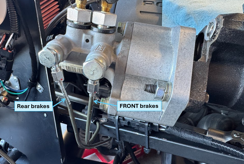
I just happened to be reading through TTimmy's build thread and saw a comment from the one and only Jeff Kleiner about the brake line routing to the master cylinder. He mentions that the front port on the master cylinder should route to the rear brakes and the rear port should route to the front brakes. The explanation that follows seems to make sense to me. In all my years on this forum I had never seen that comment or discussion before....so it got me wondering how I routed my brake lines. Sure enough, I did the same thing. Only difference is I've got a hydroboost in my setup.
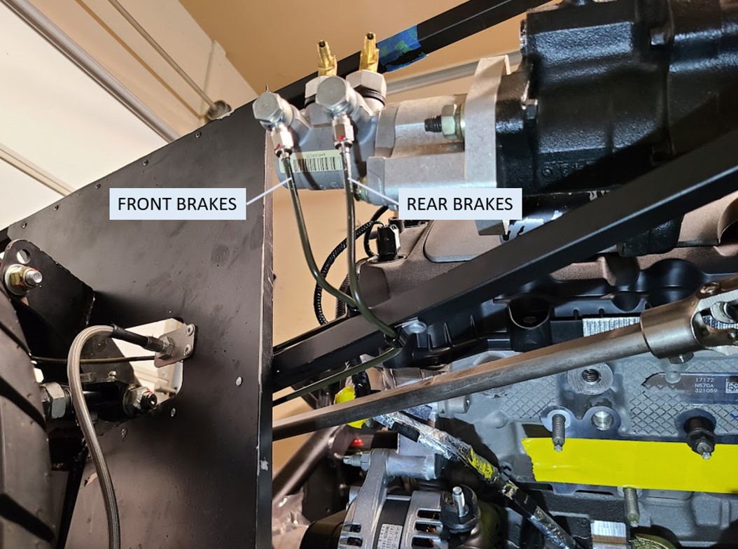
So today I went ahead and crossed the hard lines going into the master cylinder banjo connections. The process wasn't too bad - I used a syringe to pull all the brake fluid out of the reservoirs just in case they wanted to drain when I disconnected the lines. I also elevated the hoses from the reservoirs hoping to again prevent a big mess. It seemed to work - very little came out of the ports when I disconnected the hard lines. Anyhow, here's a "after" pick. I just crossed the lines, so all should be good now (front port goes to rear brakes, and rear port goes to front brakes). I will re-bleed the brakes when I have some time.
Darryl [dbo_texas]
MKIV #9644 (build thread) (Index)
MK4 Complete Kit | Gen2 crate Coyote | Tremec T56, 3.55 IRS | power steering | hydroboost | dual roll bars | FFR carbon fiber dash | 18" Halibrands + Wilwoods | RT drop trunk kit & turn signal | front battery mount | saddle leather Intatrim Stoneleigh seats + interior accents
-
01-12-2025, 10:37 PM
#213
Senior Member

Just got caught up on your build - Good stuff!
Glad to hear you were able to sort out the brakes without too much rework.
TTIMMY!
-
02-02-2025, 10:18 PM
#214
Senior Member
-
02-02-2025, 11:25 PM
#215
Senior Member
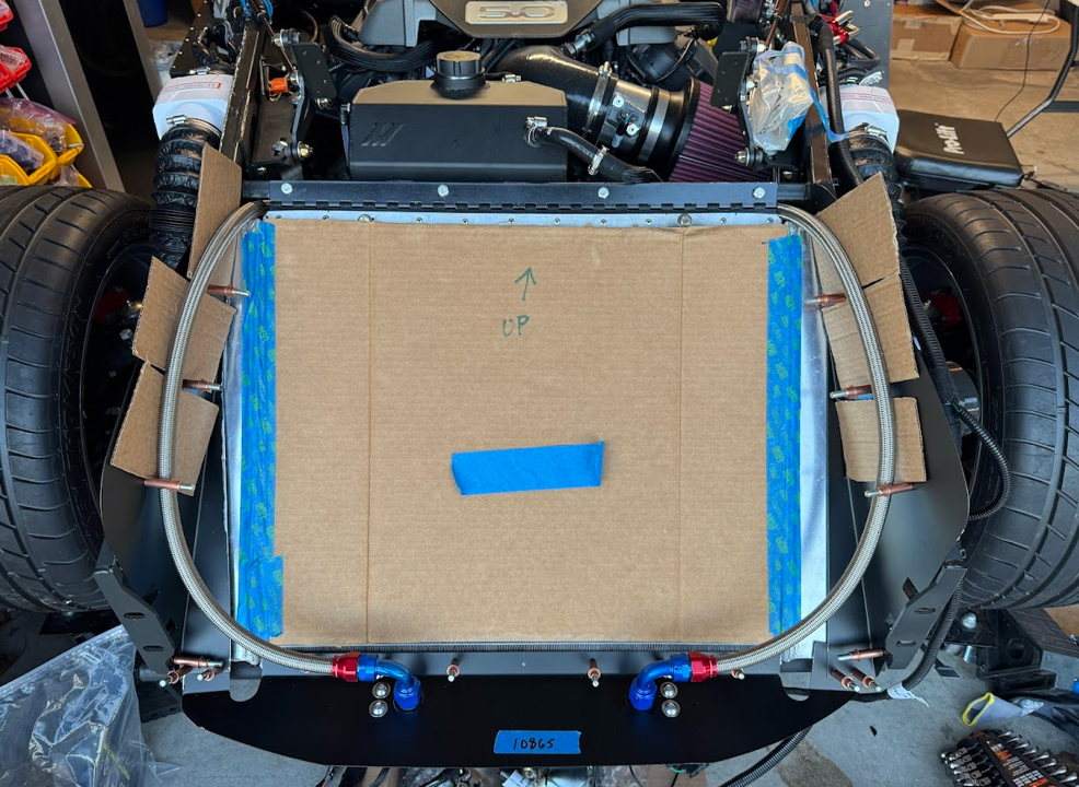
Power Steering Hose Plumbing - Coyote KRC Pump + Hydroboost + Oil Cooler
I was finally able to finish up the power steering hoses plumbing. This was a pretty big undertaking, complicated by the addition of hydroboost and an oil cooler. The hydroboost uses the power steering high pressure output to assist the brakes. And I added the oil cooler because I like the aesthetic of the cooler and hoses in the nose opening. This was a pretty expensive undertaking due to all the custom hoses I had to make - meaning lots of AN PTFE stainless braided hoses and many different types of adapters to connect it all together. I had to make a diagram to keep it all straight. This is what I ended up with - and I need to give a big shoutout to Lidodrip for helping clarify a bunch of questions. I basically mimicked his setup but with some slightly different hose routing. Here is a diagram showing all the hoses and adapters used:
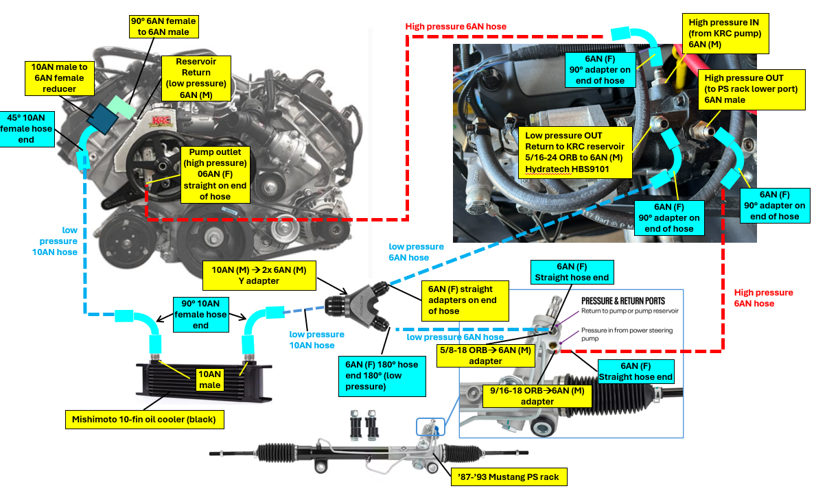
If you are interested in the specific parts I used, here's my order spreadsheet. I used 10AN hoses for the oil cooler, and everything else is 6AN. One thing to note, is that I merged the 6AN return from the hydroboost with the 6AN return from the power steering rack into a Y-adapter which has a 10AN output. The output of the Y-adapter goes to the oil cooler, then back to the KRC pump. I guess one thing to note here --> I ended up NOT using (2x) of the Russell 620421 (high pressure right angle 6AN PTFE hose end) and (1x) Russell 620401 because I was able to use the power steering hoses that came with the KRC setup from FFR and just cut off one end and terminate with the connector of my choosing. So I plan on returning those.
Spreadsheet of parts I used: Worth noting that you need to be real careful when buying AN fittings - for power steering you need to use the PTFE hoses which can handle high pressure, and make sure to get the corresponding AN hose ends made for PTFE hose....many are made for EPDM or other hose types and won't work with PTFE. You will know it is the right one if it has the separate little metal ferrule that goes on the end of the hose and the adapter goes into:
https://docs.google.com/spreadsheets...it?usp=sharing
Here are some pictures from the build. Every one of the hoses was custom built to length. I cut the PTFE using an angle grinder with a cutoff wheel and wrapped the hose with electrical tape where I made the cuts. This prevented the cut end from fraying until I could get the adapters installed. I started off installing the nose aluminum. I know this isn't supposed to go on until after the body, but I needed to fit the lower piece at a minimum so I could mount the oil cooler. The two side pieces come out easily (just using clecos for now) and can be trimmed and put back on after the body. For the lower piece, I will try to trim in place, but I realize I may have to disconnect the hoses and remove it which would kind of suck. We'll see if it can fit under the body without removing. I can always trim it in place if it is interfering anywhere. To start with the sides, I aligned the notches with the holes for the quick jack studs - this was a tip i.e.427 garage mentions on their video HERE.
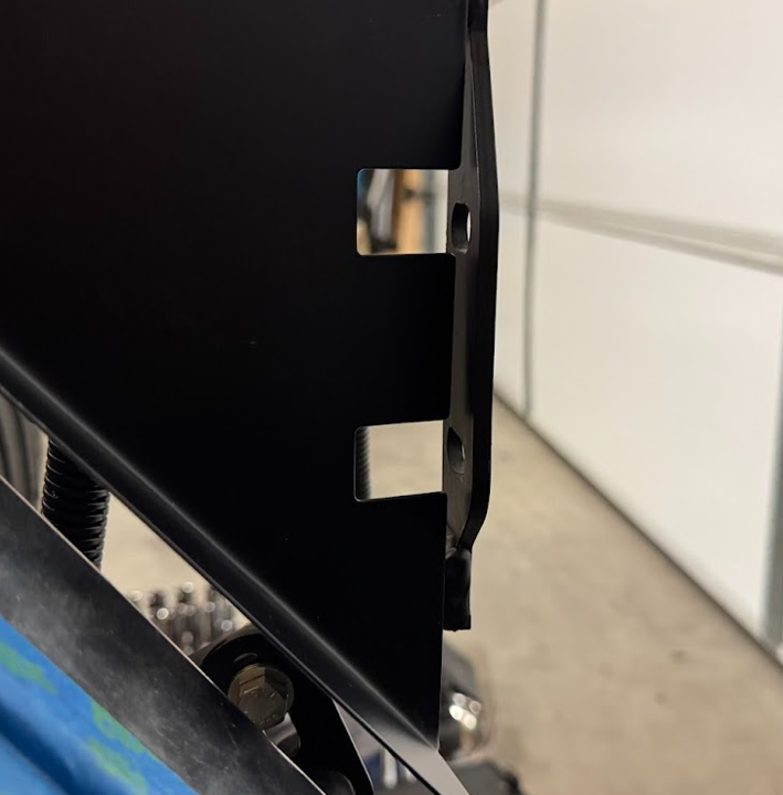
Here are the left, right and lower panels mounted. I'm aware Replicaparts makes a nice shroud piece for the nose, but I'm personally not a fan of the rounded appearance so wanted to try to make the FFR pieces work.

After removing the lower panel, I carefully measured where the oil cooler needs to go to center it on the radiator and cut the holes and mounted it. I didn't use the FFR template from their oil cooler install instructions because my oil cooler was different and the holes didn't line up with my parts. I do worry the body will not be centered and therefore the oil cooler won't be centered in the opening....I'll reevaluate when the body goes on. Worst case, I can make another lower panel but hopefully this will work out.
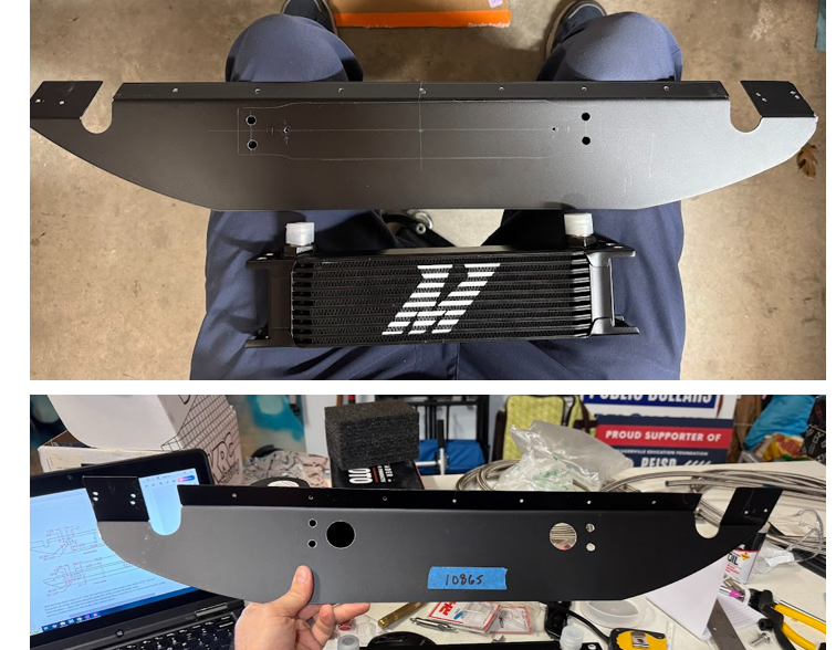
Some shots of the oil cooler installed onto the panel:
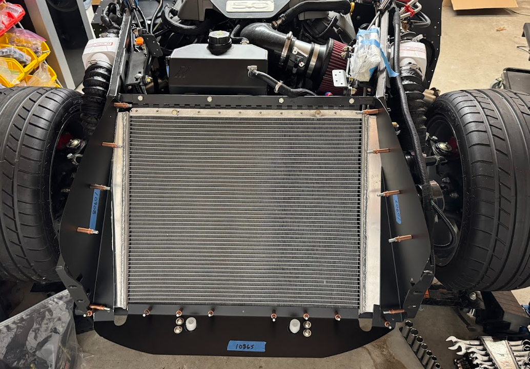
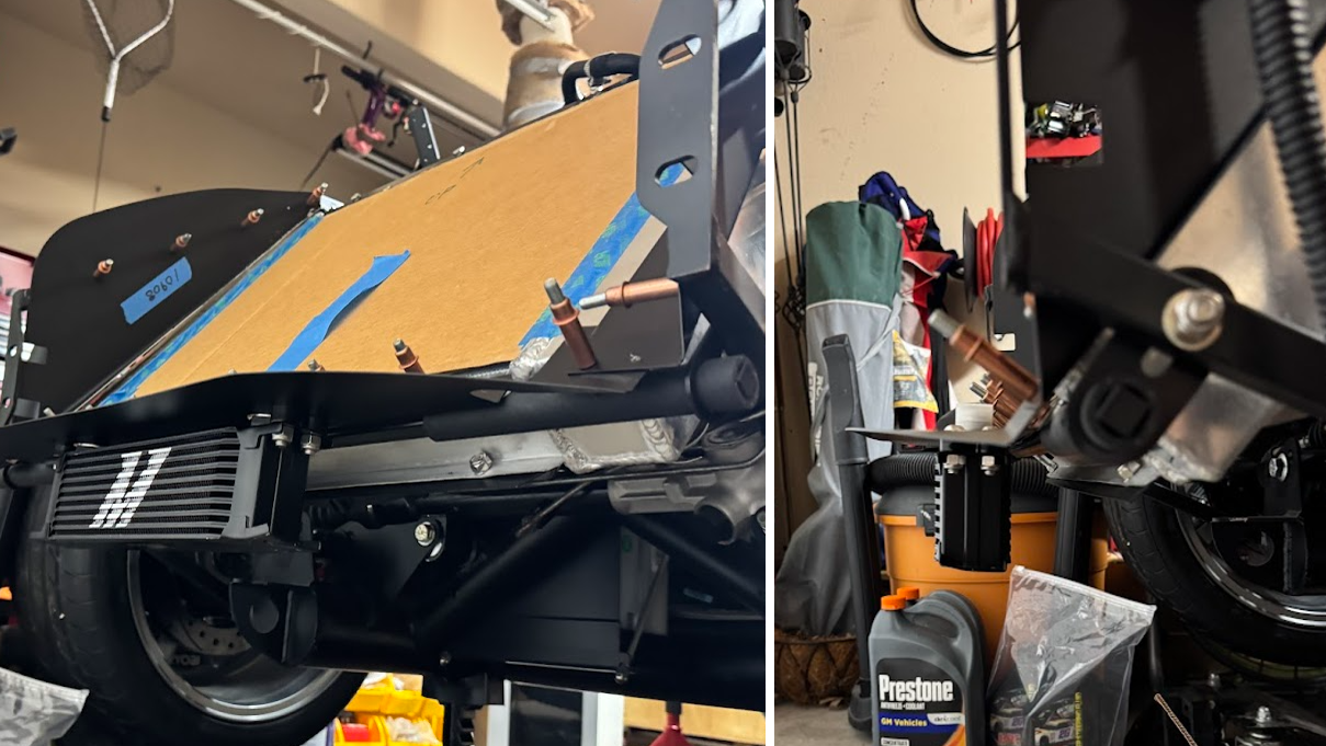
And here it is with the hoses installed. I have some cardboard on the sides to keep the braided stainless hose from rubbing off the powder coat. I ended up just removing those side panels since I planned on removing them anyways to fit after the body goes on. I ended up routing the hoses up to the top of the radiator instead of punching holes into the side panels. There are a few reasons for this. One, I like the look of the hoses routed this way, and two, if I have to disconnect the hoses later to get the body one, that's two less parts I'd have to deal with. Again, maybe this will change after the body goes on but for now this is the plan. I did add a couple of hose clamps to secure them to the side panels after final assembly.
Here is a video walkthrough of the hose routing:
Darryl [dbo_texas]
MKIV #9644 (build thread) (Index)
MK4 Complete Kit | Gen2 crate Coyote | Tremec T56, 3.55 IRS | power steering | hydroboost | dual roll bars | FFR carbon fiber dash | 18" Halibrands + Wilwoods | RT drop trunk kit & turn signal | front battery mount | saddle leather Intatrim Stoneleigh seats + interior accents


 Thanks:
  Likes:


 Reply With Quote
