-
Senior Member

I spent the weekend putting thermal barrier in the DS foot box. Didn't go too bad. All the other parts that will be installed later in the build are all ready to go.
PXL_20241005_193411290.jpg PXL_20241005_171406407.PORTRAIT.jpg
I thought it would be best per the recommendation of the forum to get the Coyote pedal installed..... This is where the fun begins. The cutting went fine, I got a little aggressive on the upper ear but not too bad. I may be conservative on the side that nests to the bar on the vehicle inner. Per what others have seen the lower hole lines up, but the upper ear hole is off 3/8", and hitting the shaft, and the inside surface is just touching the inner chassis bar with the circular proud rib. The body is also hitting the foot box pedal cross bar in the front. In the end it very clear the entire thing wants to go up about 1/4". The bracket cant go up without re drilling the fire wall, and the lower (lower is no big deal). The bracket also has no slots (wish they added this) and due to the shape you cant move the upper hole down on bracket more than 1/8" because its into the radius. Dont forget if you too high you cant get the connector on the throttle as the SS master mount will block you.
Sitting here... Trying to figure out the best play.
1. cutting the bar is out.... BAD!
2. Ive see Edward's plate, it has potential but I need some plate stock
3. I could try to slot the hole and cut more off the side at the circular rib
4. Spacers.... not my favorite idea.
5. cut the bracket at the top radius and re weld it a material thickness lower effectively raising the mount and re drilling the lower hole.
PXL_20241006_225246096.PORTRAIT.jpg
Opinions welcome.
Last edited by M22_COBRA; 10-08-2024 at 04:11 PM.
-
Senior Member
I sat in front of the foot box for about 3 hours thinking on what to do, I'm sure we have all done it lol. What came to me in the final hour as the best course of action was to redrill the firewall and raise the bracket. I didn't want to eclipse holes so I am going to use a larger 3/16 rivet .25" grip which uses a smaller hole and provides adequate offset to the existing hole. The bracket ended up needing 3/8" vertically. Its trapped by the MC bracket, firewall, inner panel flange and its still bolted to the original hole in the bottom (added new mating hole on the chassis side). I can barely get it out or in position, I don't know how this would fail and come loose on the road. The result is plenty of room & clearance everywhere. I haven't run the pop rivet yet, I will add washers on the backside to take up the extra length.
PXL_20241009_001015065.jpg PXL_20241009_001115924.jpg PXL_20241009_001004143.jpg
The end result seems pretty legit but I haven't run it home yet. Trying to figure if I want to chop the bottom per the instructions and flip or leave it down. Either way under full stroke it has 3/8"-1/2" clearance to the tightest spot on the pedal to the inner panel. The pedal is planar with the edge of the 1"x1" but clear to sheet metal ( I installed the upper to check.) Thoughts on that?
PXL_20241009_001054977.jpg PXL_20241009_001030700.jpg
Last edited by M22_COBRA; 10-09-2024 at 12:15 PM.
-
Senior Member
Finally ran the throttle pedal home. Happy with the end result, it would be nicer to have a smidge more room but that's just this car from what I understand.
Since then I've been going back and forth adding thermal mat and riveting in panels. Hindsight 20/20 I would have cut the thermal pads before I installed but it's not that bad. I do recommend two tools that help the install of the thermal deadening. #1 Amazon trim tool kit which will be useful for padding and getting sharp and stuffed corners with the carpet.
PXL_20241011_223955896.PORTRAIT.jpg
#2 is a high heat gun. Mine goes to 800+F and I can dial the heat in to help it conform to an odd corner or stick to a edge.
I also made my own close out panel for the bottom. The gap was just way too big and I was afraid of the structural integrity without it. Is I rolled the mail around the 4" tube and made a right angle. Worked great.
PXL_20241015_233928073.jpgPXL_20241009_231809157.jpgPXL_20241005_205419488.jpg
Still have some more thermal to add in the PS box but the the result was exactly what I was after in the engine Bay. Clean, slightly polished, and sealed nicely.
PXL_20241015_234020676.jpg
-
Senior Member
I have the pro m hanger and the complete kit FFR fuel cell and have a question. I have been on hiatus for work in and vacation but I had some time to get back on the project with the fuel system. On assembly it was a bit tricky to get the hanger and the pump in after a small trim to the opening per the instructions, but it's in.
On assembly it seems the unit in the full installed position feels really tight vertically, almost compressed. I have no other adjustment. If I raise the pump in the hanger, the sock won't have enough "grab" on the pump to stay installed. My fear is there is not enough "curtain" area under the pump and at full song it could be restricted. Any thoughts?
IMG_20241208_180828_076.jpgPXL_20241208_230320978.jpg
PXL_20241105_003349662.jpg
-
Senior Member

Can you look in through the filler neck hole in the tank and see how much clearance you have between the pump and the floor of the tank? I have the same hanger, and now I'm curious. I installed mine and didn't give it another thought.
Built an early MkIII years ago, sold years ago. Back after 18 years to build a MkIV
Build Thread Here Partners: Levy Racing, Summit Racing, LMR, Breeze, Forte's Parts, Speedhut, ReplicaParts
MkIV Complete Kit Ordered 4/18/23, Delivered 7/11/23, Boss 427W, Edelbrock Pro Flo 4, TKX (.68 5th), IRS, Wilwood Brakes, 18" Halibrands, Toyo R888R Tires, Custom Speedhut Gauges
-


Originally Posted by
M22_COBRA

I have the pro m hanger and the complete kit FFR fuel cell and have a question. I have been on hiatus for work in and vacation but I had some time to get back on the project with the fuel system. On assembly it was a bit tricky to get the hanger and the pump in after a small trim to the opening per the instructions, but it's in.
On assembly it seems the unit in the full installed position feels really tight vertically, almost compressed. I have no other adjustment. If I raise the pump in the hanger, the sock won't have enough "grab" on the pump to stay installed. My fear is there is not enough "curtain" area under the pump and at full song it could be restricted.
Any thoughts?
IMG_20241208_180828_076.jpgPXL_20241208_230320978.jpg
PXL_20241105_003349662.jpg
It should just be hanging in the tank and certainly not tight or compressed. Did you get it fully into the sump? if you look through the filler neck hole on the side with a flashlight you should be able to tell. Take the rubber fitting out of course.
When in the sump, the hanger is relatively close to the inside of the sump wall. If you have the sock facing the sump wall instead of the opposite direction, it can feel a little tight as well. Best bet is to turn it around so the sock can unfold into the sump instead of being bunched up.
Last edited by cv2065; 12-28-2024 at 11:19 AM.
-
Senior Member
No I can't Tell how close it is to the sump wall. The sump itself is a little half dish and it's high enough that I can't see in all that well. Typically, I'm used to having the same cylinder area available for it to pull in via a cylindrical area calculation which should be equal or greater to the area of the 2D sump pickup... No?
It's definitely not hanging, and I feel that there is a slight bit of room to allow the sock to be between the gold metal hanger and the sump container in the fuel cell. But I don't know how hard it's smashing down on that thing, it feels pretty tight.
My other thought would be to put the sock inside the gold frame hanger, raise the pump up, and possibly shorten the pickup fuel hose to be able to raise it some. I just don't know. It just feels super tight.
Last edited by M22_COBRA; 12-28-2024 at 08:13 PM.
-
Originally Posted by
M22_COBRA
No I can't Tell how close it is to the sump wall. The sump itself is a little half dish and it's high enough that I can't see in all that well. Typically, I'm used to having the same cylinder area available for it to pull in via a cylindrical area calculation which should be equal or greater to the area of the 2D sump pickup... No?
It's definitely not hanging, and I feel that there is a slight bit of room to allow the sock to be between the gold metal hanger. Aunt the sump container in the fuel cell. But I don't know hard it's smashing down on that thing, it feels pretty tight.
My other thought would be to put the sock inside the gold frame hanger, raise the pump up, and possibly shorten the pickup fuel hose to be able to raise it some. I just don't know. It just feels super tight.
If you are looking in from the side with a flashlight and pull up on the hanger you should be able to see where the sock is pointing and that the hangar is in the sump. I'd also make sure that the sock is still secure and it didn't get knocked loose.
-
Senior Member
This might be the best picture I can get you. Trouble is I can see it but I can't touch it to understand how much Gap the sock has between the hanger and the bottom of the sump.
Does this look right?
PXL_20241229_012419393.jpg
-
Senior Member
I'm sure it's fine. Countless folks have installed this hanger in this tank. Can't imagine yours would be out of whack.
Built an early MkIII years ago, sold years ago. Back after 18 years to build a MkIV
Build Thread Here Partners: Levy Racing, Summit Racing, LMR, Breeze, Forte's Parts, Speedhut, ReplicaParts
MkIV Complete Kit Ordered 4/18/23, Delivered 7/11/23, Boss 427W, Edelbrock Pro Flo 4, TKX (.68 5th), IRS, Wilwood Brakes, 18" Halibrands, Toyo R888R Tires, Custom Speedhut Gauges
-
Post Thanks / Like - 1 Thanks, 0 Likes
-
Originally Posted by
M22_COBRA
I have the pro m hanger and the complete kit FFR fuel cell and have a question. I have been on hiatus for work in and vacation but I had some time to get back on the project with the fuel system. On assembly it was a bit tricky to get the hanger and the pump in after a small trim to the opening per the instructions, but it's in.
On assembly it seems the unit in the full installed position feels really tight vertically, almost compressed. I have no other adjustment. If I raise the pump in the hanger, the sock won't have enough "grab" on the pump to stay installed. My fear is there is not enough "curtain" area under the pump and at full song it could be restricted.
Any thoughts?
IMG_20241208_180828_076.jpgPXL_20241208_230320978.jpg
PXL_20241105_003349662.jpg
M22-what pump is that? It seems the bottom center input that the screen attaches to is pretty long? This would make the hanger assembly long and perhaps not fit vertically. Is the red a protective cover?
This is the Summit of 250103 pump I used with my ProM hanger, for reference. I had no fitment issues.
IMG_1172.jpeg
BUDFIVE
Complete kit order 8/28/2023
347 Ford Dyno 10/12/2023
Kit Delivery 11/28/2023
First Start 7/4/2024
Go Cart 8/31/2024
-
Senior Member

What you're installing is something a bunch of us have done. Myself on multiple builds. I suspect you're fine. But for reference, this is the bottom of that combination that was installed in my 20th Anniversary Roadster build. Two things of note: (1) There should be a small gasket between the pump inlet and the bottom of the hangar. Just visible as a black line in this picture. If missing, the pump might be pushed down more than normal. (2) Every sock I've used had the plastic ridges visible in this picture. Even if pushed against the bottom of the tank, there's still adequate passage for the fuel to enter the pump.
One other note just FYI. You referred to your tank as a "fuel cell." Confused me at first until I looked at your pictures. Yours isn't a fuel cell. That's a very specific tank made of heavier material, has a bladder, foam baffling, etc. Used in dedicated track cars and often required by certain sanctioning bodies. What you have is a standard OE Fox body Mustang fuel tank.
IMG_3409.jpg
Build 1: Mk3 Roadster #5125. Sold 11/08/2014.
Build 2: Mk4 Roadster #7750. Sold 04/10/2017.
Build Thread
Build 3: Mk4 Roadster 20th Anniversary #8674. Sold 09/07/2020.
Build Thread and
Video.
Build 4: Gen 3 Type 65 Coupe #59. Gen 3 Coyote. Legal 03/04/2020.
Build Thread and
Video
Build 5: 35 Hot Rod Truck #138. LS3 and 4L65E auto. Rcvd 01/05/2021. Legal 04/20/2023.
Build Thread. Sold 11/9/2023.
-
Senior Member
Originally Posted by
BUDFIVE
M22-what pump is that? It seems the bottom center input that the screen attaches to is pretty long? This would make the hanger assembly long and perhaps not fit vertically. Is the red a protective cover?
This is the Summit of 250103 pump I used with my ProM hanger, for reference. I had no fitment issues.
IMG_1172.jpeg
Yeah that's just the cap, it's long. There's barely enough meat on the pump after it fits thru the bracket for the sock to grab. Its the same pump I got from summit. I'm sure I'm over reacting now. 
-
Senior Member
Originally Posted by
edwardb
What you're installing is something a bunch of us have done. Myself on multiple builds. I suspect you're fine. But for reference, this is the bottom of that combination that was installed in my 20th Anniversary Roadster build. Two things of note: (1) There should be a small gasket between the pump inlet and the bottom of the hangar. Just visible as a black line in this picture. If missing, the pump might be pushed down more than normal. (2) Every sock I've used had the plastic ridges visible in this picture. Even if pushed against the bottom of the tank, there's still adequate passage for the fuel to enter the pump.
One other note just FYI. You referred to your tank as a "fuel cell." Confused me at first until I looked at your pictures. Yours isn't a fuel cell. That's a very specific tank made of heavier material, has a bladder, foam baffling, etc. Used in dedicated track cars and often required by certain sanctioning bodies. What you have is a standard OE Fox body Mustang fuel tank.
IMG_3409.jpg
EdwardB yep, used your 20th as the guide and it has the rubber squash grommet. This sock did not have the ridges, but wish it did. Nice feature. I'm sure it's a cost cutting measure I wish mine had. I'm sure I'm overreacting, past experience just raised the concern. Really appreciate the help y'all!
Sorry about the "fuel cell" comment. I'm just way too used to speaking in the race shop around my work cars... 
IMG_0027~2.jpg
-
Senior Member
Originally Posted by
M22_COBRA
Sorry about the "fuel cell" comment. I'm just way too used to speaking in the race shop around my work cars...
IMG_0027~2.jpg
No need to apologize. It's usually impossible to know the knowledge/experience level of forum members. Many first time builders here. Carry on!
Build 1: Mk3 Roadster #5125. Sold 11/08/2014.
Build 2: Mk4 Roadster #7750. Sold 04/10/2017.
Build Thread
Build 3: Mk4 Roadster 20th Anniversary #8674. Sold 09/07/2020.
Build Thread and
Video.
Build 4: Gen 3 Type 65 Coupe #59. Gen 3 Coyote. Legal 03/04/2020.
Build Thread and
Video
Build 5: 35 Hot Rod Truck #138. LS3 and 4L65E auto. Rcvd 01/05/2021. Legal 04/20/2023.
Build Thread. Sold 11/9/2023.
-
Senior Member
Lol, no more like 20 years of bad habits. Definitely not an expert at everything, always something to learn. Thanks for the help, I'll need it for sure when I get to electrical.
Last edited by M22_COBRA; 12-29-2024 at 09:38 AM.
-
Senior Member
Quick post of the night, thought I'd share. Was looking for a cap for the fuel neck A BEHR spray paint cap or an assembly lube cap fits just right.
PXL_20241229_223037885.jpg
Last edited by M22_COBRA; 12-29-2024 at 09:11 PM.
-
Senior Member
I think you mean fuel filler neck, not fuel vent. The vent is that brass 90 degree fitting in the background. Not trying to be pedantic...just correcting lest some newbies get confused.
Built an early MkIII years ago, sold years ago. Back after 18 years to build a MkIV
Build Thread Here Partners: Levy Racing, Summit Racing, LMR, Breeze, Forte's Parts, Speedhut, ReplicaParts
MkIV Complete Kit Ordered 4/18/23, Delivered 7/11/23, Boss 427W, Edelbrock Pro Flo 4, TKX (.68 5th), IRS, Wilwood Brakes, 18" Halibrands, Toyo R888R Tires, Custom Speedhut Gauges
-
Just read through your whole thread. I'm about to get into sheet metal. Like the look of your polished panels. Can you share what you use/do for the polishing? Thanks.
MK4 complete kit Nov 2024, Blueprint 347, TKX, Hyd clutch, IRS, 3.55, touring shocks, 17" wheels, 11.65 brakes
-
12-29-2024, 09:14 PM
#100
Senior Member
Originally Posted by
gbranham
I think you mean fuel filler neck, not fuel vent. The vent is that brass 90 degree fitting in the background.
100% spot on, fixed it. Doing this off the phone. Talk to text got me.
-
12-29-2024, 09:21 PM
#101
Senior Member
I use a aluminum polishing bar compound to get it clean with a wool 4" wheel. Then use a polish compound called CJ'S METAL gloss and finish with the CJs sealer.
I'll warn you. It's dirty, takes a long time, and it's very easy to go to far and burn a panel if your speed is too fast. I try to stay around 1100 rpm. Setup outside on sawhorses with clothes you don't care about and FAR away from the house or I promise the wife will have a fit. The sling is like cooper seize, it gets everywhere.
-
Post Thanks / Like - 1 Thanks, 0 Likes
 PMD24
PMD24 thanked for this post
-
12-30-2024, 06:26 PM
#102
Senior Member
Gas tank is in! I used my portable vice then lightly, slightly, and ever so politely worked the flange flat and the last movement was a small adjustment down to line it up and make it flat. I did have a set of flat bill sheet metal grips I was gonna use. But since my gorilla hand strength has left me after my surgery, this was a work smarter way of getting it done. Only chipped the paint in two small areas.
PXL_20241230_194227022.jpgPXL_20241230_194159460.jpgPXL_20241230_164015120.jpgPXL_20241230_162928377.jpgPXL_20241230_145255085.jpg
The passenger side is tight but it still has a large gap to the down bar... Normal? The tank ain't moving that's for sure.
Most of the day was spent getting the car off the dolly and onto stands. It was just up way to high and I wanted to bring it down now before the car got heavy. Had to deconstruct the dolly and it ended up being 18" tall. The jack stands have it at 19, and that's good enough. I now can get it down with the jack as it has enough drive at that height. No need for the engine hoist and straps. This way I can have the piece of mind it's on stands and If I need to move it I can drop it on the dolly and make a small adjustment.
Last edited by M22_COBRA; 12-30-2024 at 06:28 PM.
-
01-13-2025, 08:58 AM
#103
Senior Member
Its been a while. The cold and work have slowed me severely.
Got going on the tank install, minor drama on the straps but not too bad, I left the PS strap less than snug per the instructions. Something about sheet metal adjustment?
I took an idea from another forum member and got me a $20 amazon fuel filter and turned it into a carbon vapor can with some cheap-o fittings and ran the line. Mounted it on the front side of the 1x1 tank post.
PXL_20250111_191649604.jpgPXL_20250111_193853800.jpg
I had the Aeromotive regulator to get the necessary 65 psi for my gen 3, all the fittings form Frangiola, and the line but the Trick flow reservoir has been on backorder for months now out of Summit. I saw that Aeromotive made a new combination 10 micron filter and regulator unit and I was curious. As I have read from other members that they may have put the regulator in the back since after the tune they remove the regulator gauge and never touch it again. It got me thinking if I were to do so with the connections at the rear, if there was ever a problem with a leak at the regulator then the fuel would just dump out back of the car vs dumping on the engine.... so I went for it. Got to say I actually really like it! The Aeromotive part (AEI-13147) is very well made and used the FFR Filter mount with some edge trim on the flanges, some sound deadener foam for fretting and mounted it up on the chassis ( I think this chassis plate is for a 3 bar mount). I have no use for it since I am IRS. This setup actually saved me a few bucks since I have less connections /required fittings and less line needed.
Its a short run off the tank then back again. I have good access from underneath and servicing should be easy as I also made the bracket removable to the chassis, 10-24 w/ nylock once I get to the hardware store. All I have to do now is run the line to the front and get it close to its last clipping point.
PXL_20250111_214646066.jpgPXL_20250111_214709122.jpgPXL_20250111_194958173.jpgPXL_20250112_215619754.jpgPXL_20250111_214635175.jpg
Last edited by M22_COBRA; 01-13-2025 at 10:41 AM.
-
01-18-2025, 04:43 PM
#104
Senior Member
Mocking up potential reservoir positions, and I think I found one I like. The question is where I have them. The cap is about half an inch below the top 1x1 bar that the body sits on. The hood has a recess which comes down. Does it look like this is too high and the hood will hit it? I'm about out of vertical adjustment with the ffr reservoirs. The next step would be to increase the bracket but I don't know how far is too far and then you're below the Masters? Feedback appreciated.
PXL_20250118_213533888.jpgPXL_20250118_213613881.jpgPXL_20250118_213719518.jpg
-
01-18-2025, 05:27 PM
#105
Senior Member

Yours look about where mine are located, the top is close to center of the square tube. No issues.
-
Post Thanks / Like - 1 Thanks, 1 Likes
-
01-18-2025, 09:33 PM
#106
Senior Member
Thanks, F500guy appreciate the input. Hard to tell without the body and hood on. Figured I'd dip in to the experience pool on this one. I guess worst case it would require a new bracket which I made removable for unforeseeable reasons like these.
-
01-20-2025, 11:46 AM
#107
Senior Member
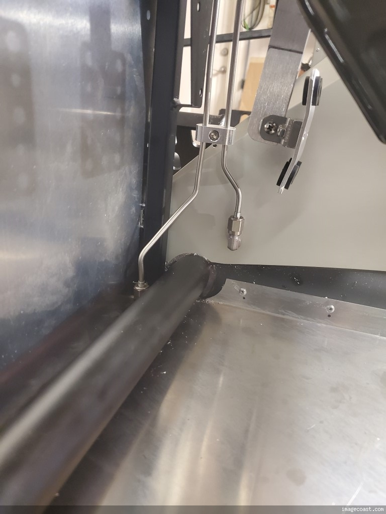
Got started on brake hardlines, WIP. Plan is to build the pass thru side door on the drivers box with grommets. I considered running the rear down inside the footbox like others have done. I just wasn't sure I liked it and how it would play with the carpet ( above / below). The plan at the moment is to cross over the steering bearing, clip where necessary, and drive straight down the front of the foot box. I also plan on making a fabricated heat shield for just the brake line with the appropriate material. Done it before on my "other cars" and it works well when done correctly (per the brake temp sensors in the scrutineering data). Again, All WIP. May be easier if I drop in the engine temporarily and hook up the header to get the full concept? Probably not that big of a deal. Any thoughts welcome.
PXL_20250119_221159401.jpg PXL_20250119_221214775.jpg PXL_20250119_221149460.jpg
Last edited by M22_COBRA; 01-20-2025 at 12:21 PM.
-
01-20-2025, 03:51 PM
#108
Senior Member
After some MORE photo research that may not be a good place for that line on the edge of the foot box.
-
01-21-2025, 09:35 AM
#109
Senior Member
I originally ran my rear line out the front and down under the car, ended up redoing it and running it down the inside of the driver, outside corner of the footbox, pretty easy and clean and easy realestate. I Did a hanger for fuse panel and turn signal ground along that outside frame, but I think it should work as long as you are far enough out of the way of the window frame.
Redone rear brake line cockpit.JPG
-
01-21-2025, 10:18 AM
#110
Senior Member
Originally Posted by
F500guy
I originally ran my rear line out the front and down under the car, ended up redoing it and running it down the inside of the driver, outside corner of the footbox, pretty easy and clean and easy real estate. I Did a hanger for fuse panel and turn signal ground along that outside frame, but I think it should work as long as you are far enough out of the way of the window frame.
Redone rear brake line cockpit.JPG
I'm considering what you have for sure. How does the carpet work with this -> go behind it or overtop? I'd assume behind? Looking thru your build for context.
My other thought is to go under the 1x1 all the way forward, drop down on the round tube then come back. But thats a long route.
-
01-21-2025, 10:33 AM
#111
Senior Member

It's best to run the brake lines inside the footbox. There's room behind for the carpet. I used bulkhead fittings to pass through the sheet metal.
-
01-27-2025, 10:54 AM
#112
Senior Member
Struggling with the brake lines. Got everything routed, was doing lots of practice, and tried to use the Eastwood style flaring tool but the kit lines are so hard that it pushes the line back in op1 and I don't get a bubble, but op2 flares them out. SOAB. I wrench down on the tool with a mini breaker bar and I know it gets a good clamp as I get overly aggressive witness lines on the coating but it still pushes back. I ordered some NiCopp and got that on the way, I'll try that. Question is with a double flare how does NiCopp play with a stainless 37 deg AN fitting? I have one as a bulkhead going thru the bottom of the floor like mike and PaulB have outlined previously. Following the procedures, chamfer, file edges, lube, ect.... bad times. This photo may be too high res, they don't look this cracked up in real life ??
PXL_20250126_215209042.jpg
Last edited by M22_COBRA; 01-27-2025 at 11:03 AM.
-
01-27-2025, 05:42 PM
#113
Senior Member
I've struggled with several double flare tools in the past, but on this build, I bought this one. Couldn't be easier. Perfect flares every time. I used the kit-supplied brake line.
Flaring Tool.jpg
Built an early MkIII years ago, sold years ago. Back after 18 years to build a MkIV
Build Thread Here Partners: Levy Racing, Summit Racing, LMR, Breeze, Forte's Parts, Speedhut, ReplicaParts
MkIV Complete Kit Ordered 4/18/23, Delivered 7/11/23, Boss 427W, Edelbrock Pro Flo 4, TKX (.68 5th), IRS, Wilwood Brakes, 18" Halibrands, Toyo R888R Tires, Custom Speedhut Gauges
-
Post Thanks / Like - 1 Thanks, 1 Likes
-
01-27-2025, 07:47 PM
#114
Senior Member
Carpet actually went behind the line, I may shoot a little black on the green line to make it blend in. Later after I can drive it, then good chance I will forget about it!
-
Post Thanks / Like - 0 Thanks, 1 Likes
-
01-27-2025, 09:25 PM
#115
Senior Member
Tried a few new things and still no success. It makes a fantastic single flare but the first OP for the bubble is no good. I tried a super large chamfer, mobile 220 red grease, oil, antisieze, I even placed a metal angle back stop behind the line to stop it from backing out. Nothing worked. The backstop just got me a bent piece of test line. Really hoping this roll of Nicopp I have ordered will form better. Already pissed this expensive tool isn't working.
-
01-28-2025, 09:35 AM
#116
Senior Member
Originally Posted by
M22_COBRA
Tried a few new things and still no success. It makes a fantastic single flare but the first OP for the bubble is no good. I tried a super large chamfer, mobile 220 red grease, oil, antisieze, I even placed a metal angle back stop behind the line to stop it from backing out. Nothing worked. The backstop just got me a bent piece of test line. Really hoping this roll of Nicopp I have ordered will form better. Already pissed this expensive tool isn't working.
Do you want to borrow my El Cheapo tool that works great? Happy to ship it to you, but for the price of shipping both ways, you can buy it on Amazon. I think it was around $40.
Greg
Built an early MkIII years ago, sold years ago. Back after 18 years to build a MkIV
Build Thread Here Partners: Levy Racing, Summit Racing, LMR, Breeze, Forte's Parts, Speedhut, ReplicaParts
MkIV Complete Kit Ordered 4/18/23, Delivered 7/11/23, Boss 427W, Edelbrock Pro Flo 4, TKX (.68 5th), IRS, Wilwood Brakes, 18" Halibrands, Toyo R888R Tires, Custom Speedhut Gauges
-
01-28-2025, 10:30 AM
#117
Senior Member
Don't feel bad, I never made a decent double flare in my life. I went to stainless AN fittings out of necessity.
-
01-28-2025, 11:18 AM
#118
Senior Member
Originally Posted by
gbranham
Do you want to borrow my El Cheapo tool that works great? Happy to ship it to you, but for the price of shipping both ways, you can buy it on Amazon. I think it was around $40.
Greg
Thanks gbranham, Which tool did you end up using? I see the Eastwood knockoff Titan is about $41 shipped.
-
01-28-2025, 11:19 AM
#119
Senior Member
Originally Posted by
Mike.Bray
Don't feel bad, I never made a decent double flare in my life. I went to stainless AN fittings out of necessity.
lol I may be in the same boat if this doesn't work out.
-
01-28-2025, 11:52 AM
#120
Senior Member
See post #113 above for a picture of what I used.
Built an early MkIII years ago, sold years ago. Back after 18 years to build a MkIV
Build Thread Here Partners: Levy Racing, Summit Racing, LMR, Breeze, Forte's Parts, Speedhut, ReplicaParts
MkIV Complete Kit Ordered 4/18/23, Delivered 7/11/23, Boss 427W, Edelbrock Pro Flo 4, TKX (.68 5th), IRS, Wilwood Brakes, 18" Halibrands, Toyo R888R Tires, Custom Speedhut Gauges
-
Post Thanks / Like - 0 Thanks, 1 Likes


 Thanks:
  Likes:


 Reply With Quote