-
Senior Member

My coyote won't start and I need some help- Ford now wants the harness back
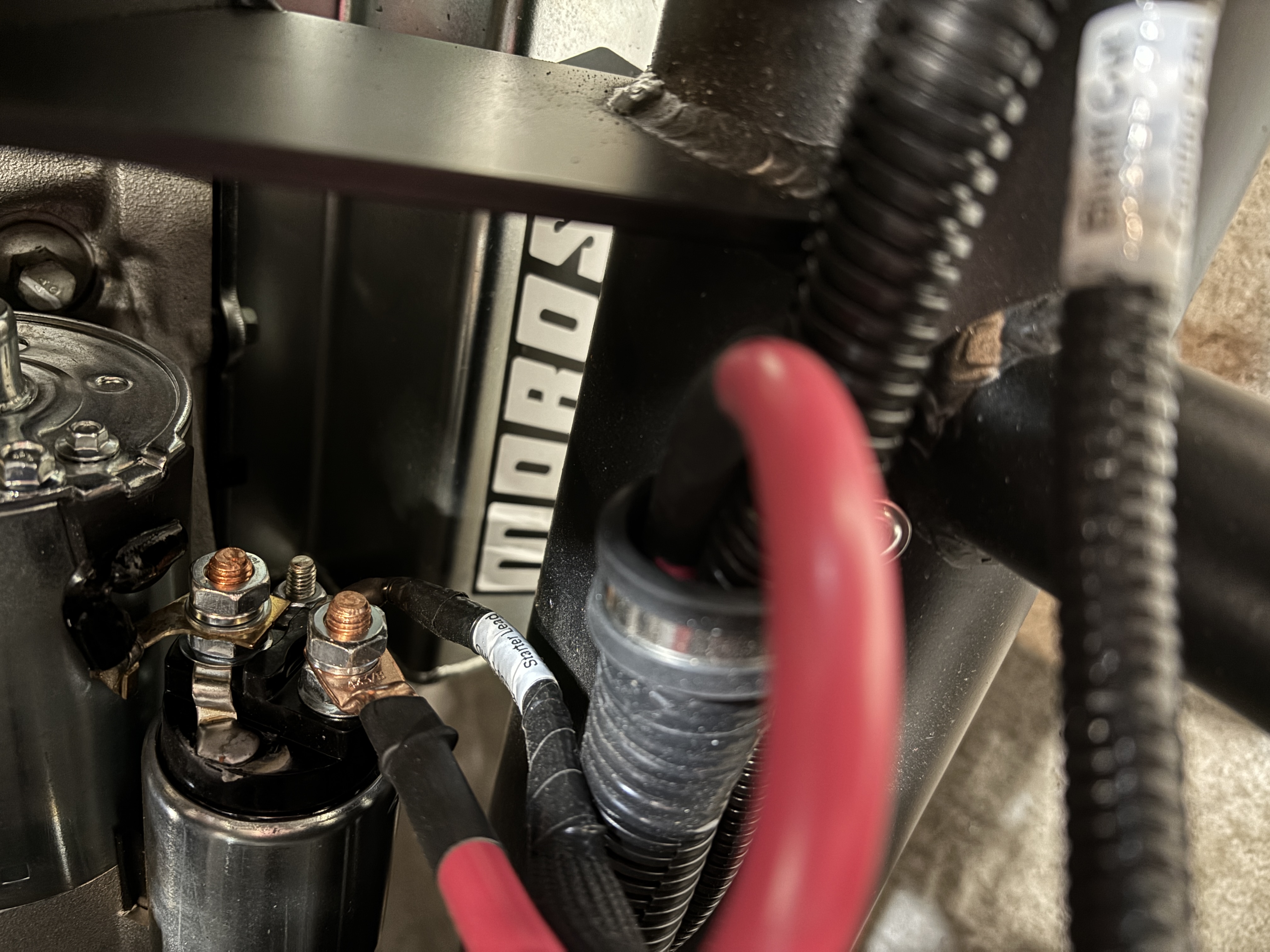
Like the title says I turned the key this morning and nothing happened. I started troubleshooting and found I am not getting any power to the starter lead to the engine solenoid. I do have 12v at the big lug as that is a direct run from the bus attached to the battery. Here is what I have tested so far.
Clutch safety switch - Verified it's open and goes to close when depressed. To make troubleshooting easier I have put a wire jumper in connector C257 so that switch is now always met.
Blue starter wire - Verified this is connected to blue SMR wire. I also verified when the key is turned to start that I am getting 12v
Orange EFI wire - Verified this is connected to the Ignition Relay Trigger. 12v is present when the key is set to run.
Ground - I was really careful to check every ground during the build. I have 5 different grounds on the control pack harness. Everyone has been tested to the battery lead. I have some other grounds in common but all my individual accessories work so if it was a ground issue I would think it would show up as having other problems as well.
Control pack fuse box - I have 12v at the fuse box at all times.
Fuses - I pulled and checked every fuse in both the PCM and RF fuse panel.
Inertia switch - Checked it, but even if it was open that would just keep the fuel pump from coming on. The fuel pump does not come on when the key is turned. I do know the pump works because I tested it with a power supply to set the pressure and check for leaks.
OBD port - I put a meter on the OBD port looking to see if I was getting a code. This is the most disconcerting part. The meter isn't getting any power, even with the key in run.
I pulled every connector and re attached, I cannot find any bent pins or opens. I used this control pack with the first engine I purchased on the dyno. The engine never ran but it turned over.
I really need some troubleshooting help. What I really need is a controls pack schematic.
Last edited by Blitzboy54; 02-08-2025 at 06:20 PM.
-
OK, so my coyote won't start and I am going to need some help

Originally Posted by
Blitzboy54

Like the title says I turned the key this morning and nothing happened. I started troubleshooting and found I am not getting any power to the starter lead to the engine solenoid. I do have 12v at the big lug as that is a direct run from the bus attached to the battery. Here is what I have tested so far.
Clutch safety switch - Verified it's open and goes to close when depressed. To make troubleshooting easier I have put a wire jumper in connector C257 so that switch is now always met.
Blue starter wire - Verified this is connected to blue SMR wire. I also verified when the key is turned to start that I am getting 12v
Orange EFI wire - Verified this is connected to the Ignition Relay Trigger. 12v is present when the key is set to run.
Ground - I was really careful to check every ground during the build. I have 5 different grounds on the control pack harness. Everyone has been tested to the battery lead. I have some other grounds in common but all my individual accessories work so if it was a ground issue I would think it would show up as having other problems as well.
PCM - I have 12v at the PCM at all time.
Fuses - I pulled and checked every fuse in both the PCM and RF fuse panel.
Inertia switch - Checked it, but even if it was open that would just keep the fuel pump from coming on. The fuel pump does not come on when the key is turned. I do know the pump works because I tested it with a power supply to set the pressure and check for leaks.
OBD port - I put a meter on the OBD port looking to see if I was getting a code. This is the most disconcerting part. The meter isn't getting any power, even with the key in run.
I pulled every connector and re attached, I cannot find any bent pins or opens. I used this control pack with the first engine I purchased on the dyno. The engine never ran but it turned over.
I really need some troubleshooting help.
As long as you're checking all connections, how about looking at the ignition switch itself? Probably wouldn't hurt to eliminate that possibility.
-
Senior Member

I had somehow hooked up the ignition wrong as well... Assuming you're using what FFR provided. Just verify all those are hooked up correctly. Do you get accessories and gauges to respond when you turn the ignition half way on? I had accidentally "dieted out" the IGN to COL cable. Once that was put back in, it fired right up. Good luck!
-
Senior Member

So, basic questions but I like basics.
Have you disconnected and reconnected your ECM cable(s) to ensure they are down and locked, no pins or connectors bent or misaligned?
It's not clear from your description but are you getting power to your fuel pump i.e. prime or does nothing happen with the key?
Also, is their a neutral lockout ground or something of that nature?
Last edited by PNWTim; 02-08-2025 at 05:00 PM.
-
Senior Member
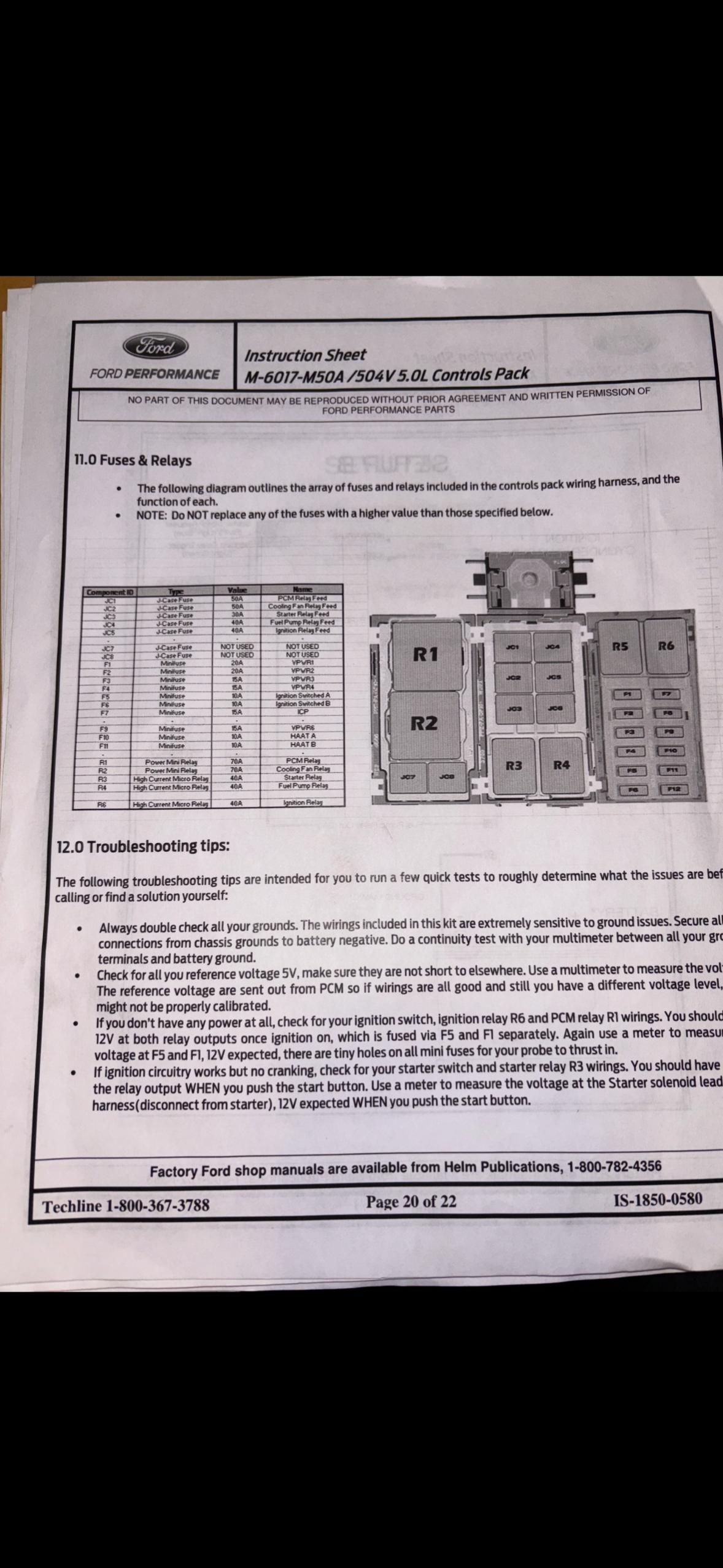
The switch is correct. The only thing I am not getting any response from is the PCM (ecu). I did some more troubleshooting and found a couple things. First I never connected the HAAT B off of the pigtail. I was following the FFR instructions probably too closely and missed this. Unfortunately connecting that has not helped. The troubleshooting guide says to check R6 (ignition relay) and R1 (PCM relay). I have power at R6 because I have power at the F5 relay. I do not have power at the F1 relay. This all tracks since my computer isn't doing anything. I pulled the relay and bench tested it, it works fine. It has incoming power but not 12v on the control side. So this all makes sense I guess. What I am unclear about is where does that 12v come from. I will call Ford on Monday but I have feeling the PCM has something wrong with it.
-
Senior Member
Originally Posted by
PNWTim
So, basic questions but I like basics.
Have you disconnected and reconnected your ECM cable(s) to ensure they are down and locked, no pins or connectors bent or misaligned?
It's not clear from your description but are you getting power to your fuel pump i.e. prime or does nothing happen with the key?
Also, is their a neutral lockout ground or something of that nature?
No, I like basics to. Thank you for the response
Yes, I have pulled those connectors several times. I looked for bent pins. I guess it might not be seated correctly but man I would have to be a dope. I will take some pics of it.
I am not getting power to anything that the coyote controls. I know these things work because I tested them individually. I also checked all the incoming power from the RF harness. It's all there.
Yes there is a neutral lockout switch. I checked to make sure the switch was working (it is). I then jumpered out the connector so it is now closed. I suppose just to be sure I could plug it back in and tape it closed so there is no question. If it was the switch I would expect it to still prime the fuel pump I think but I don't know for sure.
-
Do you have 12 volts on the stud on the front of the relay control box?
A large red wire goes from the large fuse to that lug
Mike
-
Senior Member
I do, but I don’t have power at pin 16 on the obd port or the PCM relay which is supposed to be always hot. I’m going to ask ford for a schematic on Monday. I’m wondering if I have an open or mis wire somewhere in the harness.
I did splice in the Autometer tach converter. Maybe I did something wrong. I’m going to go everything from start to finish tomorrow and see if I missed something.
-
Senior Member

No power to the OBD port is a concern. As mentioned, it is always on.
While you’re waiting for Ford to open on Monday the best you can do is triple check your work. In my case, most problems were self inflicted!
Would love to see it fired up soon!
Build 1: Type 65 Coupe
-
Album: Coupe Album
-
Delivered: February 24, 2022,
Legal: April 20, 2024,
Complete: TBD
Build 2: Mk3 Roadster (Acquired as a partially started build)
- Build Thread: TTimmys MK3 Basket Case Build Thread - Album: Mk3 Album
-
Originally Delivered: 2004,
Acquired by me: August 2024
-
Post Thanks / Like - 1 Thanks, 0 Likes
-
Senior Member

I agree it's concerning you don't have +12V at the ODB2 port. Just a guess, but I doubt that's necessarily something with the PCM. More than likely some type of wiring issue. Either external or internal to the control pack circuitry. If you have +12V on the large bolt on the front of the PDB, the control pack +12V wires attached to it, and the control pack ground solidly attached (Ford Performance want's that to be home run to the battery) you should have voltage there and your scanner light up when plugged in. I'd be asking Ford what could cause that. Two other points FWIW, the HAAT wire is an available power source (Hot At All Times) for whatever you might want, but doesn't affect anything if not used. The fuel pump will only very briefly cycle when power first applied. It's easy to miss. It won't actually run continuously until the engine starts. If the pump is doing nothing (and assuming it's wired correctly) that also suggests the Control Pack isn't running.
Build 1: Mk3 Roadster #5125. Sold 11/08/2014.
Build 2: Mk4 Roadster #7750. Sold 04/10/2017.
Build Thread
Build 3: Mk4 Roadster 20th Anniversary #8674. Sold 09/07/2020.
Build Thread and
Video.
Build 4: Gen 3 Type 65 Coupe #59. Gen 3 Coyote. Legal 03/04/2020.
Build Thread and
Video
Build 5: 35 Hot Rod Truck #138. LS3 and 4L65E auto. Rcvd 01/05/2021. Legal 04/20/2023.
Build Thread. Sold 11/9/2023.
-
Post Thanks / Like - 1 Thanks, 0 Likes
-
I haven't seen this covered yet but also check the plug that the fuel pump ignition and starter request are plugged into. Maybe some pins got swapped. Easy check. BTW when you first turn the key on, you should hear the fuel pump as Paul stated but also the throttle body cycles too. Both of these happen regardless of the clutch switch.
Mike
-
Post Thanks / Like - 1 Thanks, 0 Likes
-
Senior Member
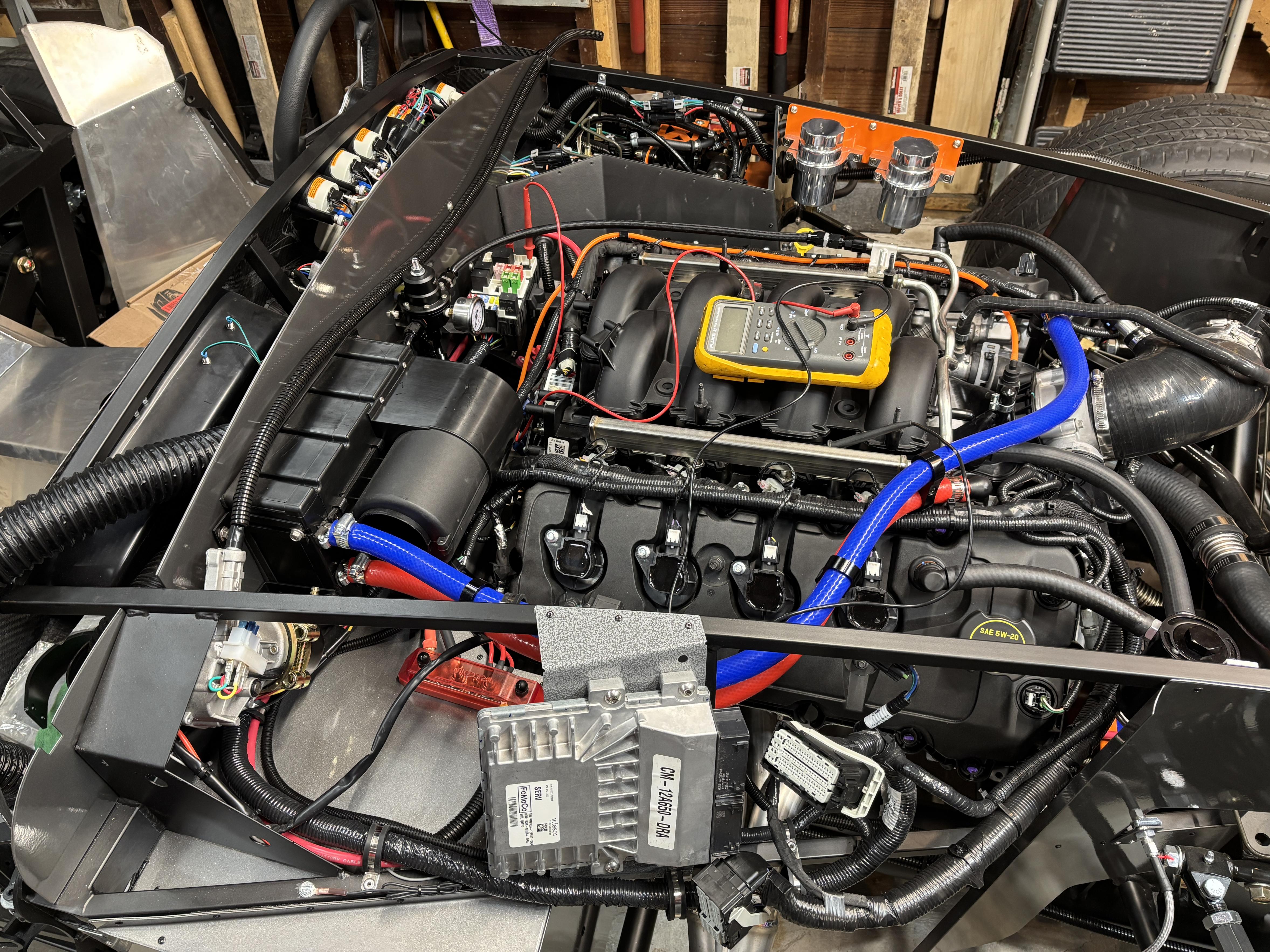
Thank you Gentlemen! I re traced my steps and have not found any obvious installation mistakes. I have pulled every connector and see no bent or recessed pins. I have been digging into the installation paperwork, old threads and the internet generally and I have found some useful stuff. I made a 5 minute video breaking down what I am seeing and what i think the problem is. Much easier to explain than it is to type it out.
PS this is unedited. I referred to a few things backwards including calling a 10 amp fuse, 10 volts.
Last edited by Blitzboy54; 03-10-2025 at 10:35 PM.
-
Senior Member
I then jumpered out the R1 relay and it woke up the ECU. So I at least now have something digital to work with. Hopefully Ford can help me figure it out from here. I sound a little more optimistic in the video than maybe I should. I am hot on it's tail but maybe further away from solving it as I implied. Got a little excited.
-
Senior Member
Troubleshooting is simply drilling down and isolating root cause which you are doing well, I definitely think you are on the right track. It'll be interesting to see what Ford says.
-
Senior Member

You sure you have the ignition key wired correctly? My Coyote would not start & the solution with a FFR supplied ignition assembly was to move all the wires one position clockwise
-
Post Thanks / Like - 1 Thanks, 0 Likes
-
On a roll

Kevin beat me to it. (tried to reply with a quote on his post, but for some reason "reply with quote" won't work. whatever)
I don't think your problem is in the fuse box. I have been down that rabbit hole and it wasn't there. The key connections in my mind, and apparently, Kevin's (BEAR-AVHistory), are the blue and orange wires as well as the pigtail connections to the ignition switch. My issues were with the connections between the pigtail and the blue/orange wires - they looked good, but weren't. Couldn't tell what connectors you are using, but I recommend something solid like a weatherpack. Spade connectors won't do. (my experience). Assuming you have the Gen II coyote controls pack installation guide, refer to page 15. light green wire - ignition relay trigger. that will start the relay/PCM.
In my opinion, based on what I have seen in this thread so far, your problem is between the ignition switch and the connections made on the C160A pigtail. I'd check those again, please.
Mk IV Roadster - #8650 - delivered 7-17-2015 - first start 7-28-2018 - first go-kart 10-13-2018 - licensed and on the road 9-9-19: body/paint completed 3-17-2020.
Complete kit / 2015 Coyote / TKO600 / IRS / Wilwood brakes / Mid-Shift mod / Power Steering / Heater and Seat Heaters / RT turn signal / Breeze radiator shroud and mount
-
Post Thanks / Like - 1 Thanks, 0 Likes
-
Senior Member
Originally Posted by
BEAR-AvHistory
You sure you have the ignition key wired correctly? My Coyote would not start & the solution with a FFR supplied ignition assembly was to move all the wires one position clockwise
Great idea! I went out and double checked everything on my iginition switch. I am getting voltage to the appropriate lugs when and where I am supposed to. I suspected as much because of the testing I had done before but certainly needed to check again.
Originally Posted by
Al_C
Kevin beat me to it. (tried to reply with a quote on his post, but for some reason "reply with quote" won't work. whatever)
I don't think your problem is in the fuse box. I have been down that rabbit hole and it wasn't there. The key connections in my mind, and apparently, Kevin's (BEAR-AVHistory), are the blue and orange wires as well as the pigtail connections to the ignition switch. My issues were with the connections between the pigtail and the blue/orange wires - they looked good, but weren't. Couldn't tell what connectors you are using, but I recommend something solid like a weatherpack. Spade connectors won't do. (my experience). Assuming you have the Gen II coyote controls pack installation guide, refer to page 15. light green wire - ignition relay trigger. that will start the relay/PCM.
In my opinion, based on what I have seen in this thread so far, your problem is between the ignition switch and the connections made on the C160A pigtail. I'd check those again, please.
I had checked these before but not in a comprehensive way. I pulled the C160B pigtail connector from behind the dash, unplugged it and went wire to wire. There are 5 total wires (7 in the instructions but the MIL is now integrated directly and not present on the connector) on the pigtail so lets take them one at a time.
Wire 1 Green - Fuel pump. I have continuity from the RF relay (orange) to the pin on the connector. When I jumpered the R1 relay I heard it prime so safe to say that works
Wire 3 Light Blue - Starter wire (SMR) - I have this connected to the blue start wire per the instructions. When the key is turned all the way to start I get 12v at the pin
Wire 5 Light Green - Ignition relay trigger - i have the orange EFI wire connected. When the key is turned to run I get 12v at the pin, also when I had the R1 relay jumpered this activated the throttle body and pump as it was designed to do. I can assume that connection is correct.
Wire 8 Red - HAAT B - I have constant 12v at this pin.
Wire 9 Black - Chassis ground - I ohmed this pin back to the battery and it reads 1ohm. Of all my grounds this is the most resistance I get anywhere but still pretty low.
Keep the ideas coming. I really appreciate it.
-
Senior Member

When you give it ignition are you able to open the throttle body by pressing the accelerator pedal?
Did you ground the PCB to the battery (check out edwardb 25th anniversary build thread, very nice guide & how he did it)?
If you put a jumper wire between the 12v and start terminal on the starter itself does it turn?
If you jump the start request at the R3 relay do you get it to turn?
Check the grounds again and again. Check the one on the PS front engine that is on one of the front cover studs towards the top too. My coyote in the cobra build a few years ago wouldn't kick. After weeks of f'n around on it it turned out it was a broken ring terminal on the clutch switch. It looked fine but inside the shrink sleeve it snapped and wasn't making a circuit. Stay on it and you'll get it sorted!
I'm having coyote issues too... As wrote in my thread I'm pretty certain because of all the edits to my engine and it's upsetting the ecu.
Build 1: MKIV #7275 Gen 2 Coyote TK600, IRS 3.55 2020 Graduated
Build 2: Gen3 65 Coupe: Arrived June 2024. Gen 2 Coyote, T56, IRS 3.55
-
On a roll
Originally Posted by
nuhale
If you put a jumper wire between the 12v and start terminal on the starter itself does it turn?
If you jump the start request at the R3 relay do you get it to turn?
Nuhale is on to something here. These two tests would be my suggestion for a next step as well. They'll help you determine if the problem is in the PCM or the wiring integration.
Mk IV Roadster - #8650 - delivered 7-17-2015 - first start 7-28-2018 - first go-kart 10-13-2018 - licensed and on the road 9-9-19: body/paint completed 3-17-2020.
Complete kit / 2015 Coyote / TKO600 / IRS / Wilwood brakes / Mid-Shift mod / Power Steering / Heater and Seat Heaters / RT turn signal / Breeze radiator shroud and mount
-
Do you have a ground from the chassis to the engine block?
Mike
-
Senior Member
Originally Posted by
nuhale
When you give it ignition are you able to open the throttle body by pressing the accelerator pedal?
Did you ground the PCB to the battery (check out edwardb 25th anniversary build thread, very nice guide & how he did it)?
If you put a jumper wire between the 12v and start terminal on the starter itself does it turn?
If you jump the start request at the R3 relay do you get it to turn?
Check the grounds again and again. Check the one on the PS front engine that is on one of the front cover studs towards the top too. My coyote in the cobra build a few years ago wouldn't kick. After weeks of f'n around on it it turned out it was a broken ring terminal on the clutch switch. It looked fine but inside the shrink sleeve it snapped and wasn't making a circuit. Stay on it and you'll get it sorted!
I'm having coyote issues too... As wrote in my thread I'm pretty certain because of all the edits to my engine and it's upsetting the ecu.
Originally Posted by
Al_C
Nuhale is on to something here. These two tests would be my suggestion for a next step as well. They'll help you determine if the problem is in the PCM or the wiring integration.
Good stuff here. I put the jumper back and yes the TB rotates with the pedal. As an aside I purchased a used one and for the first time realized it makes a lot of noise. Might need a new one but I digress. I also gave the key a turn and the starter engages. It cranks over. It encouraging actually.
Originally Posted by
michael everson
Do you have a ground from the chassis to the engine block?
Mike
Yes, generally speaking I am ground wire obsessed. I test every ground back to the battery and to each other. I also checked a bunch of random points on the block and heads to the battery. All good
-
Senior Member
-
Senior Member
I know this is pretty frustrating for you (at least it would be for me) but I am pretty impressed with your diagnostic skills. I am learning a lot and filing it away for my install this spring and really appreciate you documenting what you have done, what has worked, not worked, etc. I feel like you are pretty close to a solution.
-
Senior Member
Didn't go through anything like this with my two Coyote builds. Hats off to how you're digging into this and hopefully soon be successful. I'm guessing the factory that made that harness did some type of automated point-to-point continuity testing. Pretty standard in the industry. The company I worked for had a harness plant so saw some of that up close. But anything's possible. Another forum member some years ago also with a Gen 2 control pack did have a defective harness and Ford eventually replaced it. The PDB is a standard Ford fuse box. Look under the hood of almost any recent Ford vehicle and you'll see the same part. I have to imagine there's instructions or a video out there somewhere showing how to take it apart. If necessary. Often things like this turn out to be simple solutions or even sometimes obvious ones in hindsight. Hopefully that's the case for you.
One other thing -- and this is a real flyer and doesn't 100% match your symptoms -- but awhile back another forum member had a no-start Coyote. Turns out he had the ignition switch wiring incorrectly. The ACC and IGNITION were reversed. The result was with the key in RUN it was electrically in ACC. Resulting in +12V to the orange EFI wire in the key RUN position, but since ACC is shut off in the START position, the Coyote wouldn't start. The control pack instructions properly point out that a solid +12V must be on the Light Green - Ignition relay trigger wire or the engine won't start or run. Just suggesting to confirm that +12V exists in both RUN and START positions. Probably you have checked, but thought I would mention it.
Build 1: Mk3 Roadster #5125. Sold 11/08/2014.
Build 2: Mk4 Roadster #7750. Sold 04/10/2017.
Build Thread
Build 3: Mk4 Roadster 20th Anniversary #8674. Sold 09/07/2020.
Build Thread and
Video.
Build 4: Gen 3 Type 65 Coupe #59. Gen 3 Coyote. Legal 03/04/2020.
Build Thread and
Video
Build 5: 35 Hot Rod Truck #138. LS3 and 4L65E auto. Rcvd 01/05/2021. Legal 04/20/2023.
Build Thread. Sold 11/9/2023.
-
On a roll
Here's something else to think about. Maybe. Am I correct that your Gen II is a remanufactured unit? What about the controls pack and PCM? Did you buy them all together or separately? From Ford or elsewhere?
Here's where I'm going: there are two versions of the Gen II. The earlier, 2015 (like mine) have TWO clutch switches, upper and lower. The newer 2017 Gen II has one. So if your parts were purchased separately, you could have unintentionally received a 2017 harness for a 2015 PCM. If that were to be the case, the PCM would be looking for input from a clutch switch that you don't have. Not saying that this is the case, but worth confirming.
Mk IV Roadster - #8650 - delivered 7-17-2015 - first start 7-28-2018 - first go-kart 10-13-2018 - licensed and on the road 9-9-19: body/paint completed 3-17-2020.
Complete kit / 2015 Coyote / TKO600 / IRS / Wilwood brakes / Mid-Shift mod / Power Steering / Heater and Seat Heaters / RT turn signal / Breeze radiator shroud and mount
-
Post Thanks / Like - 0 Thanks, 1 Likes
-
Senior Member
Thank you everyone for your continued input. The number one rule of brainstorming is there are no bad ideas. Even if it's far fetched it may trigger another idea so please continue to chime in if you think of something.
Paul, yes sir I have check that a couple times. I am getting voltages where appropriate.
Al - This is interesting and I called Ford back. They are still working on getting schematics but I asked specifically about this. They said there is an issue sometimes but with donor parts. A new harness and control pack should marry up. I have a M-6017-M50A control pack and a M-1200-M50 harness.
I may have found the problem
But that is the end of the good news for a moment. I continued to be baffled by the lack of HAAT power. Particularly since I know I have HAAT A because it's the 12v that come in from the 4awg lug directly from the battery. HAAT B comes from the 16 pin connector.
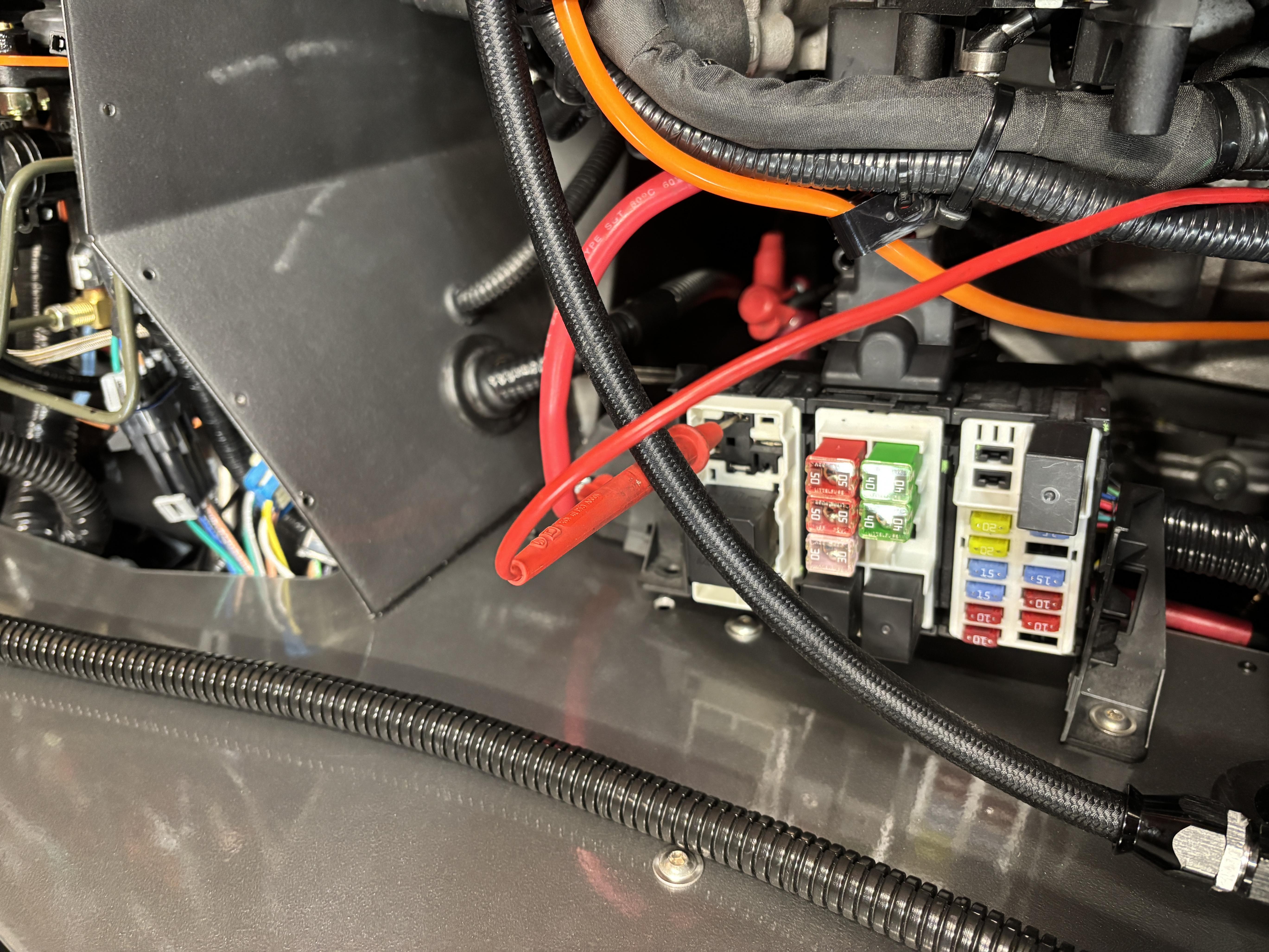
I took the fuse box off as best I could. I removed all power (battery disconnected) and removed the back of the box. What I found was interesting. As you can see in this picture my screw driver is pointing to a red wire. That is the control voltage to the R1 relay. That should be hot all the time. The other side is a link to ground. Thats how these switches work. I know this supposed to the HAAT power because if you follow this wire back there is a large red wire that is spliced to the R1 relay and both fuses F10 and F11. HAAT A is the main bus so why would they all be linked together? That is curiosity number 1.
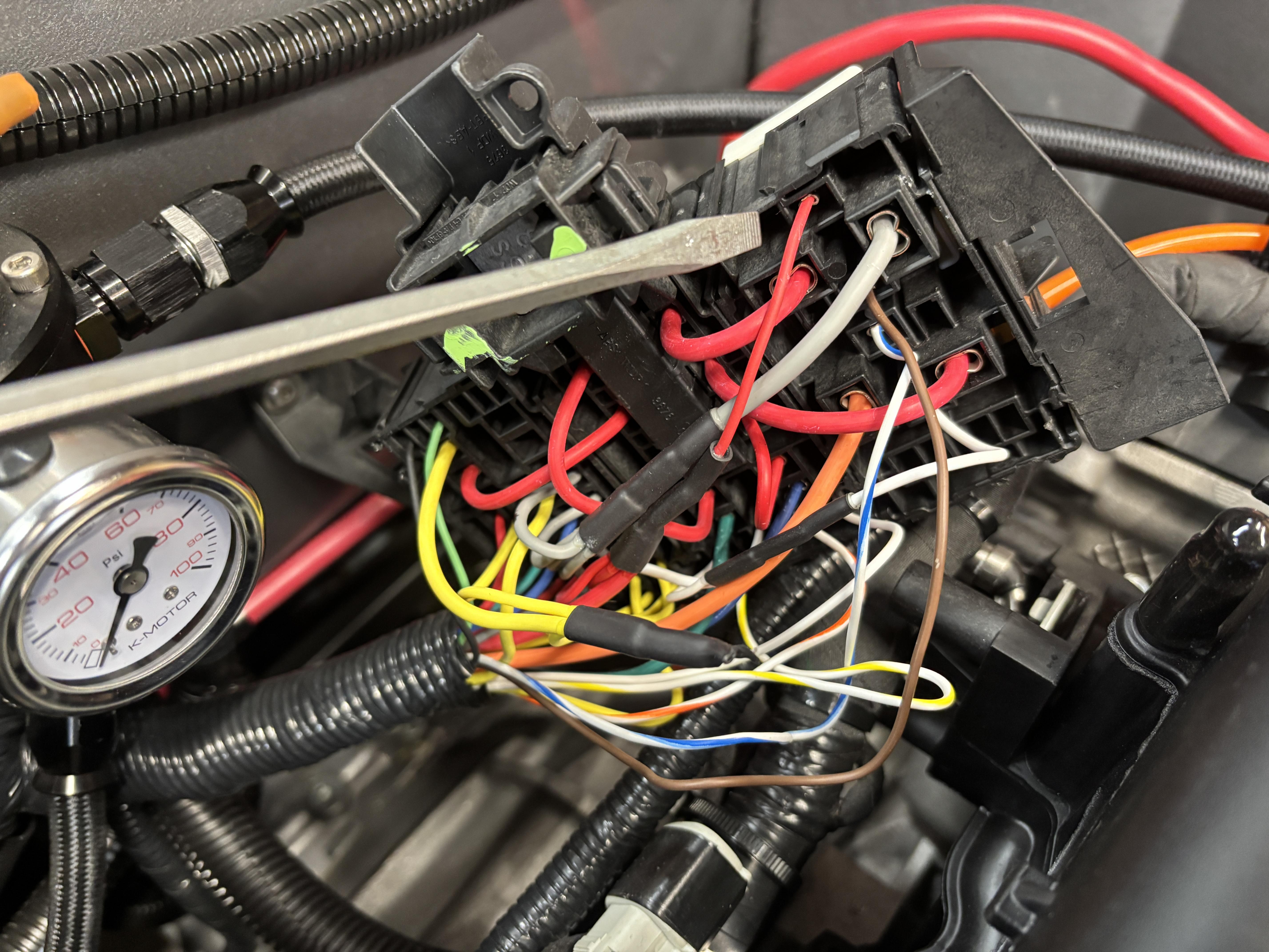
So I went back to the source of HAAT B power (the 16 pin connector top left socket) and measured continuity to the incoming side. Not only do I have a complete open (this tracks) I have continuity to ground. I clearly have a short somewhere I am guessing in the harness control pack. Everywhere HAAT B power is supposed to go I have continuity to ground. This includes Pin 16 on the OBD port. I am putting all of this into a mass email with pictures and diagrams for the Ford folks.
-
If there's any silver lining to this, you'll know the harness better than you ever would otherwise. Kudos on your persistence and logical diagnosis. It seems like you're getting closer.
-
Post Thanks / Like - 1 Thanks, 0 Likes
-
Sorry to hear you are going through this. I had a no start condition when I was trying to get my Gen III Coyote going. Very frustrating and worked with the Ford techs for a few weeks trying different things. I had power to the ECM and basically rewired the car to verify everything was correct. Couldn't find anything wrong and in the end, we determined that the ECM didn't have a complete program flashed and needed to be sent back to Ford. I sent it back and waited a couple weeks for it to return, plugged it in and it fired on the first try..... Only two months wasted. As is understand it, there is no QC process to verify the programming and function before these units are shipped.
Lars
Novice Build: 289 USRRC Complete Kit #10524, 3rd Gen Coyote, TKX, IRS, 17" Halibrands, Wilwood Brakes, Power Steering
-
Post Thanks / Like - 1 Thanks, 0 Likes
-
Sounds like you have done a lot of work. Won't be consistent with a short, but when I wired my tach into the coil wire, I unwittingly left it unplugged. My engine wouldn't turn over.
Ken
MK4 #10476, complete kit, Gen 3 Coyote, TKX with 0.68 overdrive, 3.55 Mustang IRS, 18" rims, dual rollbar, Carbon fiber dash,
Ordered 12/18/2021, Deliverd 9/24/2022, First Start 6/24/2023, Licensed 6/2024
-
Post Thanks / Like - 1 Thanks, 0 Likes
-
Senior Member
Also just for the record. I misunderstood what HAAT B was. That’s not an input but a usable pigtail. I’ve pulled the fuse to remove it from the equation. I have no source of always on power where I should and my HAAT circuit shorts to ground. I’m guessing a wiring error or some trigger in the PCM isn’t correct
-
Senior Member
Update -
I have modified my chart I do have power at F1 when I jumper. I think I didn't have good contact on the fuse the first time.
F1 - VPWR1 - 12v
F2 - VPWR2 -12V
F3 - VPWR3- 12V
F4 - VPWR4 -12V
F5 - IGNITION SWITCH A - 12V
F6 - IGNITION SWITHC B - 12V
F7 - ICP- 12V
F9 - VPWR6 - 12V
F10 - HAAT A - 0
F11 - HAAT B - 0
I will post it later because I am on my work computer and don't have access at the moment but I have a full service manual for a 2016 Mustang GT. HAAT power comes from a contactor internal to the PCM that is activated when the key is turned to start. Mine is not contacting. This also might explains why anything tied to the HAAT circuit is short to ground. HAAT power runs power to all the sensors and OBD port so this tracks.
It's early but the Ford people have not been real responsive. They said they would email schematics and it hasn't happened yet. It's fine, I think I figured it out but here's what happens next. I found a used PCM on ebay for cheap. It won't run the engine but if I turn the key and the engine comes alive and the OBD port has power I will have identified root cause. I can then push back on Ford and ask for this unit to be repaired or replaced. I guess it's possible there is break in a wire somewhere but that feels less likely. I still need schematics to show me what to test.
One step at a time.
***Edit***
Just as I say that Ford called. We are in agreement on what the problem the absence of the HAAT. We also agree that it is either the PCM not triggering it or the wire harness not providing the trigger signal. They will send me some tests later today. Also may send me a test PCM. Either way I am confident we will figure it out. Now that I know I don't have any fuel leaks having fully tested the system I may work on the aluminum in the back of the car to stay busy.
Last edited by Blitzboy54; 02-11-2025 at 12:12 PM.
-
Post Thanks / Like - 0 Thanks, 5 Likes
-
Senior Member
I keep waiting to see your thread pop back up to the top. I am guessing you have gotten delayed.
-
Senior Member
I plan to call Ford back today. He said I was his "top" priority but have not received any wiring diagrams yet. I purchased a used PCM with the same PN that arrives today. I will at the very least see if when I turn the key to on if the engine wakes up and I have HAAT power. If so problem solved. I will send back the PCM to Ford and have them fix or replace it.
If I have a problem in the harness I really need the diagram. I don't want to pull apart the harness. I don't think there are any other relays or switches outside the Fuse panel but I don't know without documentation.
My daughters conference swim championships are this weekend so I have tonight otherwise I am out of commission until Monday. I would like those diagrams by Friday. A weeks seems reasonable.
-
Post Thanks / Like - 0 Thanks, 1 Likes
-
Senior Member

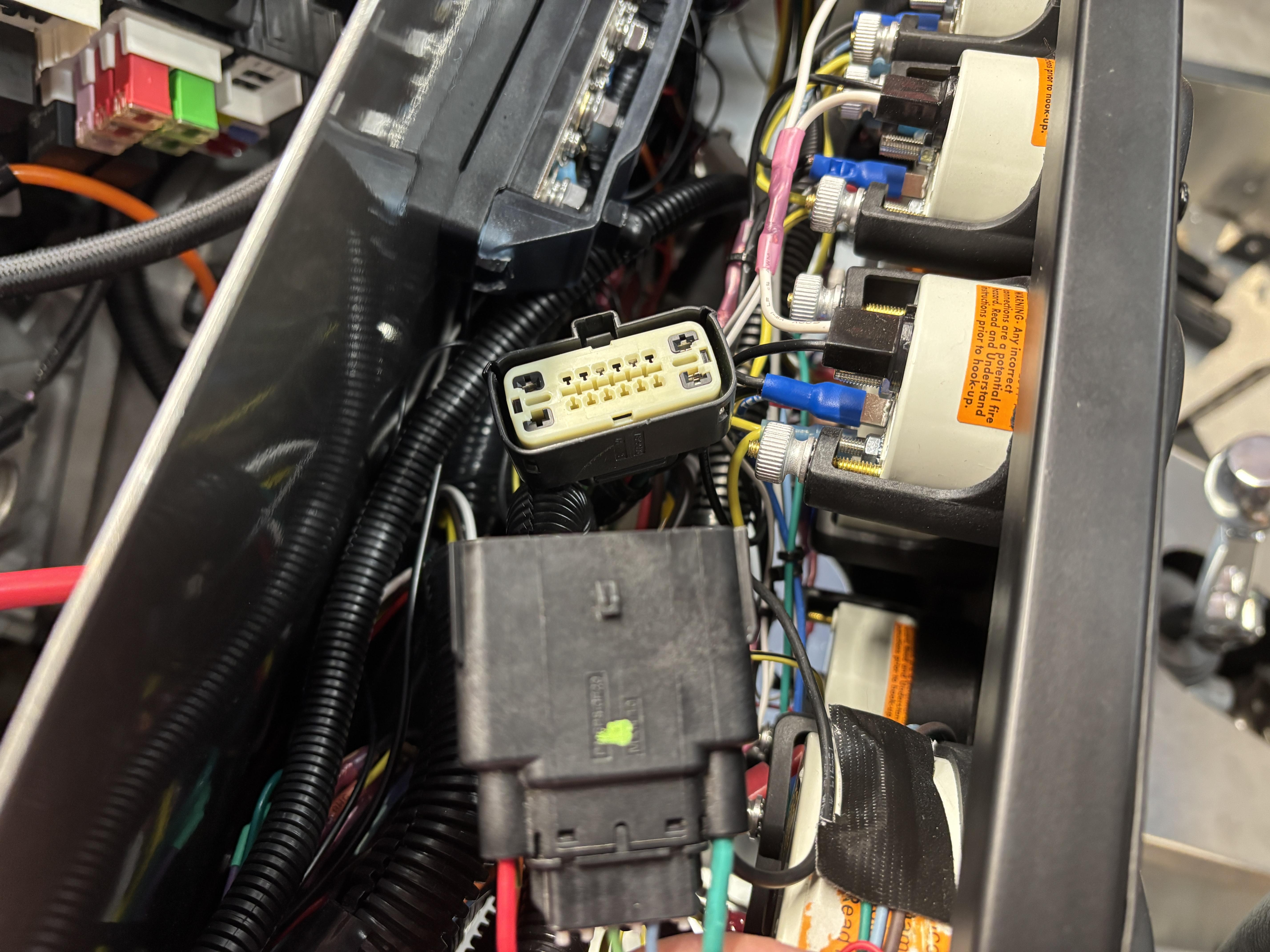
Is it just the camera angle? Looking at the photo showing the 16 pin connector, it looks like the light blue & green wires are not in the same pin location on the male side as the female side???
Mrk III, 331 stroker, Borla stack injection, T5, 3:55 IRS, Power steering and brakes. Kleiner body & paint
-
Senior Member
Originally Posted by
rich grsc
Is it just the camera angle? Looking at the photo showing the 16 pin connector, it looks like the light blue & green wires are not in the same pin location on the male side as the female side???
Thanks Rich, I think that's a camera trick. Last night I traced the green wire back. Since my ignition circuit works I traced that wire back from the relay. The blue and green are where they should be and getting the appropriate voltage.
For anyone that is interested when you turn the key the green wire (fed from the orange EFI on the RF) energizes relay R6. That is the trigger side. The relay then opens and is powered from the 12v that comes from the main battery input. The big red wire feeds a bus, the bus in turn feeds all the "output circuits". They are all ground controlled from the PCM. The issue I have on mine is I have power at the output circuit of R1 but the trigger voltage comes from the HAAT (Hot at all times) voltage. That also feeds the MIL and provides power to the OBD port. Once I solve the HAAT issue I think the problem goes away.
This is where I am lost. The HAAT power comes from somewhere back in the harness. I need the wiring diagram to test where. The PCM doesn't provide any high current power just ground triggers to trip relays. The ignition relay sends big 12v back to up the wiring harness on the yellow wires. I suspect that is tied somehow to the HAAT. I will find out hopefully soon.
-
Senior Member
I completely isolated the control pack harness. I unplugged it from the PCU, the engine harness, the MAF, alternator, 16 pin connector, throttle, clutch switch and MIL. The only physical connection it has to my car is the 12v battery lug at the fuse panel and the grounds.
With that I have a dead short to ground from any HAAT connection to ground of 0.1 ohm.
I still really want to see a wiring diagram. My preference would be to fix this but it might be time talk about replacing the control pack harness.
Last edited by Blitzboy54; 02-13-2025 at 07:16 PM.
-
Senior Member

When an electrical system has a dead short, put a globe (50-100 watt) in series with the battery as a current limiting device. An added bonus is that the globe will be bright when there is a short, but will reduce brightness or go out when the fault is removed. Also saves fuses from being blown and reduces 'stress' on the electrical system whilst testing.
Hope you find the culprit soon.
Cheers,
Nige
Mk.4 FFR supplied Right hand drive
Received 12/2012 completed 12/2019
Gen1 Coyote / TKO600 / IRS
Lots of mods to make compliant for Australian design rules
-
Senior Member
Anyone with a Gen 2 coyote, regardless of what kind of vehicle it’s in, do me a favor? I need 2 measurements both with the engine completely powered off. First at the fuse box, please measure if there is 12v at F10. There are little probes at the top of the fuse. If there is 12v let me know. If there is not 12v can you then take a continuity measurement from F10 to chassis ground? Is it open or do you have continuity to ground?
IMG_5592.jpg
This can also be done from pin 16 of the OBD2 port if the fuse box is difficult to bet to. Whatever is easier.
IMG_5602.jpg
Last edited by Blitzboy54; 02-14-2025 at 10:19 AM.
-
Originally Posted by
Blitzboy54
Anyone with a Gen 2 coyote, regardless of what kind of vehicle it’s in, do me a favor? I need 2 measurements both with the engine completely powered off. First at the fuse box, please measure if there is 12v at F10. There are little probes at the top of the fuse. If there is 12v let me know. If there is not 12v can you then take a continuity measurement from F10 to chassis ground? Is it open or do you have continuity to ground?
IMG_5592.jpg
This can also be done from pin 16 of the OBD2 port if the fuse box is difficult to bet to. Whatever is easier.
IMG_5602.jpg
I am HAAT any both locations.
-
Senior Member
Originally Posted by
jiriza84641
I am HAAT any both locations.
Thank you sir.


 Thanks:
  Likes:


 Reply With Quote


