

 Thanks:
  Likes:

I've been extra busy with work lately, and that has gotten in the way of writing. Even so, I've kept up the work on the kit. Here's what I've been doing since my last update.
Front Suspension
I got two more adjustment sleeves for the upper control arms for the front suspension. Now both front wheels have negative camber. With that done, I set aside work on the front suspension for now.
front-suspension-sleeves.jpg
Shorter adjustment sleeves fitted on driver side.
Steering Rack
Now that finally got my front suspension into an approximately-correct geometry, I cut the inner tie rods to length and fitted the outer tie rods. I left plenty of extra length on the inner tie rods. I have a little more than two inches of engagement now, which should leave me enough even if I need to back off on the outer tie rods.
Gas Tank
I attached the gas tank… well… at least partially.
First off, I managed to damage the fuel tank vent as I was turning on the plastic bushing. Since I only have one 1" wrench, I mounted the plastic bushing in my vise, and turned on the vent with the wrench. I got the wrench in between the vent outlet and the vise, and since the vent metal is very soft, I sheered off the outlet as I turned to tighten. _Sigh_. I felt like a complete idiot. I ordered a replacement.
busted-fuel-vent.jpg
Busted part. It took genuine anti-talent to do this.
Next, I fitted my Walbro fuel pump into its bracket. I got these parts from Breeze Automotive. I'm hoping that this in-tank pump will work well with my MSD Atomic fuel injection system. I guess I'll see in a few more weeks once I've dropped in the engine, run some fuel lines, and hooked up some electrical connections.
After that, I struggled a bit with the gas tank itself. The fit of tank, straps, and chassis could have been better out of the box. I needed to bend the flanges on the tank to get it to mate up with the chassis better, but even after that, the straps still seem too short, especially on the passenger side. I ordered some longer socket cap bolts (3" long as opposed to the 2" longs bolts which come with the kit). They're due to arrive tomorrow, so I hope to make some more progress on the gas tank once they do.
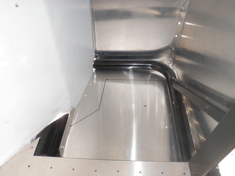
gas-tank-strap.jpg
The passenger-side gas tank strap is too short. There's no way the 2" bolt in the kit will engage. In this picture, you see a 3" bolt I tested out. Unfortunately, this bolt won't work, since the upper mount is too narrow to get a wrench or socket on it to tighten. Ugh. I ordered 3" socket cap bolts.
Aluminum
The next step in the manual is passenger-side footbox aluminum, and I made some good progress this weekend. Since I plan to mark and drill all my panels before doing any riveting (on the expert advice of MPTech), I'm using clecos during the fitting, and #6 self-tapping screws once I have all the holes drilled where I want them. I hope to move on to the driver-side footbox soon.
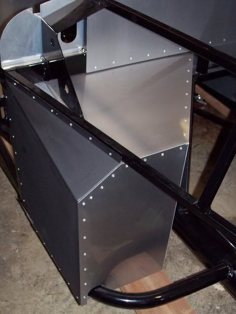
passenger-footbox.jpg
Passenger footbox coming together.
- Home
- Latest Posts!
- Forums
- Blogs
- Vendors
- Forms
-
Links

- Welcomes and Introductions
- Roadster
- Type 65 Coupe
- 33 Hot Rod
- GTM Supercar
- 818
- Challenge Series
- 289 USRCC
- Coyote R&D
- Ask a Factory Five Tech
- Tech Updates
- General Discussions
- Off Topic Discussions
- Eastern Region
- Central Region
- Mountain Region
- Pacific Region
- Canadian Discussions
- Want to buy
- For Sale
- Pay it forward
-
Gallery
- Wiki-Build-Tech

 Reply With Quote


 .
.
