FormaCars

Visit our community sponsor

Thanks Thanks:  0
Likes Likes:  0
Results 1 to 25 of 25

Thread: 2015 Coyote Control Pack

  1. #1
    Junior Member
    Join Date
    Dec 2013
    Posts
    28
    Post Thanks / Like

    2015 Coyote Control Pack

    In the process of wiring the 2015 coyote control pack and referencing Revision O of the coyote fitment for the roadster, want to insure I am not going to short anything out. Pigtail S (C160B or the 16 way I/P pigtail) has a light green wire called the ignition relay trigger and a light blue wire called the starter motor request.


    My current thought process is that I must connect the light blue (SMR) to the light blue NS Switch -Starter Solenoid wire that the coyote instructions states to cut. Is this the tan/green wire referenced in the FFR coyote instructions?

    Then splice the light green ignition relay trigger to the ignition post (orange wire) on the ignition switch.

    Is this correct?

  2. #2
    Senior Member edwardb's Avatar
    Join Date
    Feb 2011
    Location
    Lake Orion, Michigan
    Posts
    10,576
    Post Thanks / Like
    I'm also installing the 2015 Coyote and control pack in my build. I'm not far enough long to answer your question unfortunately. Due to the number of changes, I would be very careful with the Factory Five installation instructions. They have not addressed the 2015 version yet, that I'm aware of. My recommendation would be to call Ford Racing tech support. Post your solution as several of us have builds underway.
    Build 1: Mk3 Roadster #5125. Sold 11/08/2014. Build 2: Mk4 Roadster #7750. Sold 04/10/2017. Build Thread
    Build 3: Mk4 Roadster 20th Anniversary #8674. Sold 09/07/2020. Build Thread and Video. Build 4: Gen 3 Type 65 Coupe #59. Gen 3 Coyote. Legal 03/04/2020. Build Thread and Video
    Build 5: 35 Hot Rod Truck #138. LS3 and 4L65E auto. Rcvd 01/05/2021. Legal 04/20/2023. Build Thread. Sold 11/9/2023.

  3. #3
    Senior Member edwardb's Avatar
    Join Date
    Feb 2011
    Location
    Lake Orion, Michigan
    Posts
    10,576
    Post Thanks / Like
    OK, this has my interest since I'll be doing this same wiring in the next months. So instead of leaving my previous non-answer alone, I spent some time with the M-6017-504V (2015) Controls Pack instructions, the previous Controls Pack instructions, the Factory Five Coyote instructions, plus the Ron Francis wiring diagram. What I conclude is the following:

    First I assume you're planning to use "SETUP B" as outlined on page 20 of the Controls Pack instructions. Comparing everything, looks like the wiring is somewhat similar to the instructions provided by Factory Five.

    Blunt Lead 3 - Starter Motor Request (Light Blue) connect to the RF Lt Blue EFI Crank Wire. This wire correctly provides +12V when the ignition switch is in the start position. Note you could connect directly to the ignition switch, but using the loose lead would be easier IMO. Note also in this case clutch safety switch connections and the starter solenoid feeds from the RF harness are not used. Those connections are downstream from the EFI Crank Wire and not needed. The Coyote controls pack provides the safety interlock and the starter solenoid feeds directly through the PCM.

    Blunt Lead 5 - Ignition Relay Trigger (Light Green) connect to the RF Orange Coil Wire. This wire correctly provides the +12V when the ignition switch is in the start and run positions. Also you could go directly to the ignition switch, but the loose lead is easier. I used this same wire on my last build as the ignition sense wire for the MSD box. Same function here.

    Blunt Lead 8 - Hot At All Times (Red) if I understand correctly does not need to be connected. It appears to be always on +12V from the Controls Pack. But the BAT connection on the ignition switch is already providing always on +12V and ultimately from the same source. The instructions say "as needed" so my understanding would be it's not needed in this case.

    Blunt Lead 16 - Key On 12V/10A (Yellow) if I understand correctly, connect to the ACC lug on the ignition switch.

    I don't see the tan/green wire you asked about referenced in the FFR coyote instructions anywhere in the previous Controls Pack instructions. But it is pictured on a previous page in the FFR instructions, and it's labelled as "Starter Feed to Solenoid." The new Controls Pack has a separate leg coming out of the main harness by the PCM for the starter solenoid feed. So nothing to do with any tan/green wires on the new Controls Pack.

    Hope this makes sense, and please check my work but I'm pretty sure this is correct. I am concerned about one thing though. You have Revision O of the Coyote fitment for the Roadster? Can I ask where you got it? The most recent one I received is Revision L, dated 05/27/15. If there's a newer one, I sure would like to get my hands on it.
    Last edited by edwardb; 11-30-2015 at 07:51 AM.
    Build 1: Mk3 Roadster #5125. Sold 11/08/2014. Build 2: Mk4 Roadster #7750. Sold 04/10/2017. Build Thread
    Build 3: Mk4 Roadster 20th Anniversary #8674. Sold 09/07/2020. Build Thread and Video. Build 4: Gen 3 Type 65 Coupe #59. Gen 3 Coyote. Legal 03/04/2020. Build Thread and Video
    Build 5: 35 Hot Rod Truck #138. LS3 and 4L65E auto. Rcvd 01/05/2021. Legal 04/20/2023. Build Thread. Sold 11/9/2023.

  4. #4
    Junior Member
    Join Date
    Dec 2013
    Posts
    28
    Post Thanks / Like
    Quote Originally Posted by edwardb View Post
    OK, this has my interest since I'll be doing this same wiring in the next months. So instead of leaving my previous non-answer alone, I spent some time with the M-6017-504V (2015) Controls Pack instructions, the previous Controls Pack instructions, the Factory Five Coyote instructions, plus the Ron Francis wiring diagram. What I conclude is the following:

    First I assume you're planning to use "SETUP B" as outlined on page 20 of the Controls Pack instructions. Comparing everything, looks like the wiring is somewhat similar to the instructions provided by Factory Five.

    Blunt Lead 3 - Starter Motor Request (Light Blue) connect to the RF Lt Blue EFI Crank Wire. This wire correctly provides +12V when the ignition switch is in the start position. Note you could connect directly to the ignition switch, but using the loose lead would be easier IMO. Note also in this case clutch safety switch connections and the starter solenoid feeds from the RF harness are not used. Those connections are downstream from the EFI Crank Wire and not needed. The Coyote controls pack provides the safety interlock and the starter solenoid feeds directly through the PCM.

    Blunt Lead 5 - Ignition Relay Trigger (Light Green) connect to the RF Orange Coil Wire. This wire correctly provides the +12V when the ignition switch is in the start and run positions. Also you could go directly to the ignition switch, but the loose lead is easier. I used this same wire on my last build as the ignition sense wire for the MSD box. Same function here.

    Blunt Lead 8 - Hot At All Times (Red) if I understand correctly does not need to be connected. It appears to be always on +12V from the Controls Pack. But the BAT connection on the ignition switch is already providing always on +12V and ultimately from the same source. The instructions say "as needed" so my understanding would be it's not needed in this case.

    Blunt Lead 16 - Key On 12V/10A (Yellow) if I understand correctly, connect to the ACC lug on the ignition switch.

    I don't see the tan/green wire you asked about referenced in the FFR coyote instructions anywhere in the previous Controls Pack instructions. But it is pictured on a previous page in the instructions, and it's labelled as "Starter Feed to Solenoid." The new Controls Pack has a separate leg coming out of the main harness by the PCM for the starter solenoid feed. So nothing to do with any tan/green wires on the new Controls Pack.

    Hope this makes sense, and please check my work but I'm pretty sure this is correct. I am concerned about one thing though. You have Revision O of the Coyote fitment for the Roadster? Can I ask where you got it? The most recent one I received is Revision L, dated 05/27/15. If there's a newer one, I sure would like to get my hands on it.
    Thanks Edward. Spent most of the day trying to decipher what lead should go to what. This definitely helps.

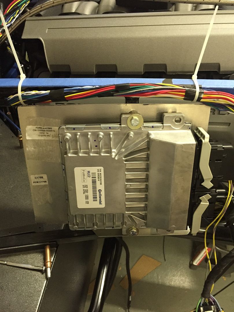
    Will likely keep this thread going with my control pack progress to help others out. FFCars forum doesn't seem to quite get the traffic this one does but I have been posting their as Supercat where you have also been a great help. Stole your location for where to mount the PCM although I don't have a box break so I went a more simple route and re-purposed some of the old sheet metal since I went with the 2bking sheet metal mod.


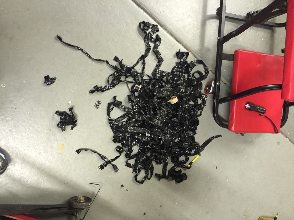
    Not sure it was worth all the effort to get rid of three wires from the main PCM connector and two from distribution box. But that did give me an opportunity to reroute the lead for the starter solenoid which gave me some more length and rerouted the orange fan lead. I actually unwrapped everything up to the main distribution box and ran the fan wire up the drivers side so I could hide it with the MAF and alternator leads. I left the intercooler plug, just in case!

    This was the mess I made.


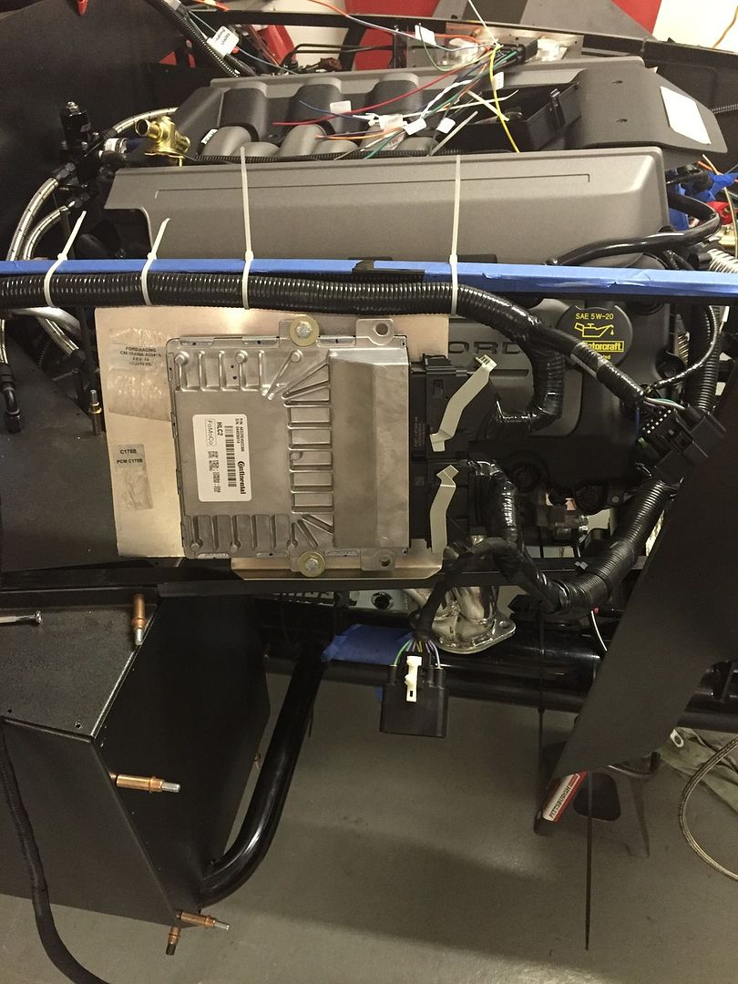
    But removing the excess leads and relocating the fan power enabled me to really clean up the wire bundle.


    Mounted the distribution box in the same location you did but decided to run my penetration in the small triangular piece of sheet metal directly under the PDB, helped conceal the mess of wires I need to bring into the cabin.


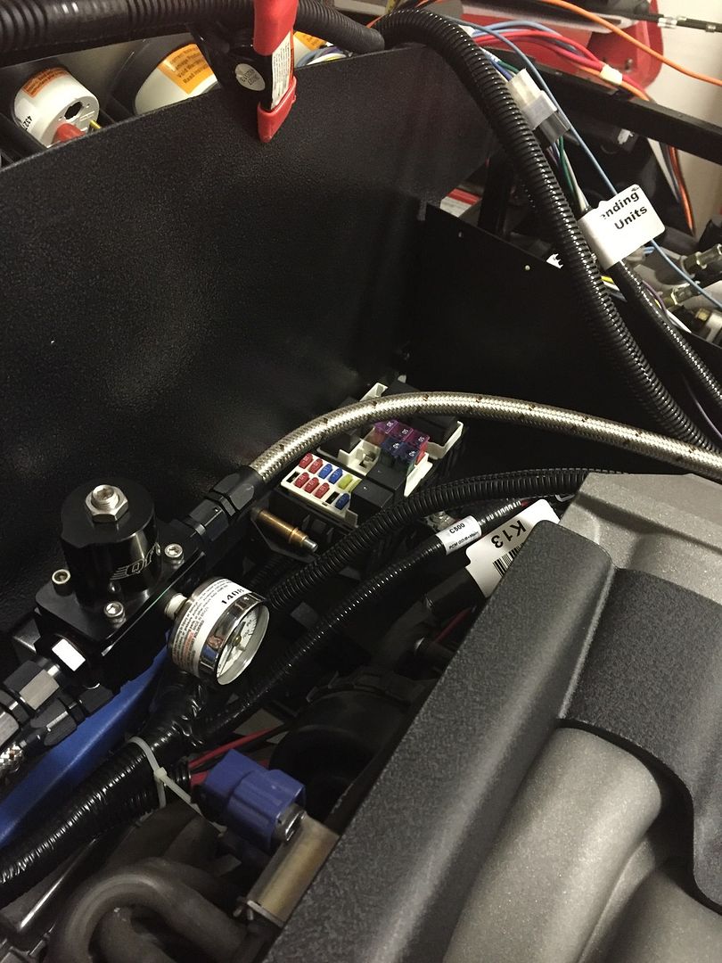
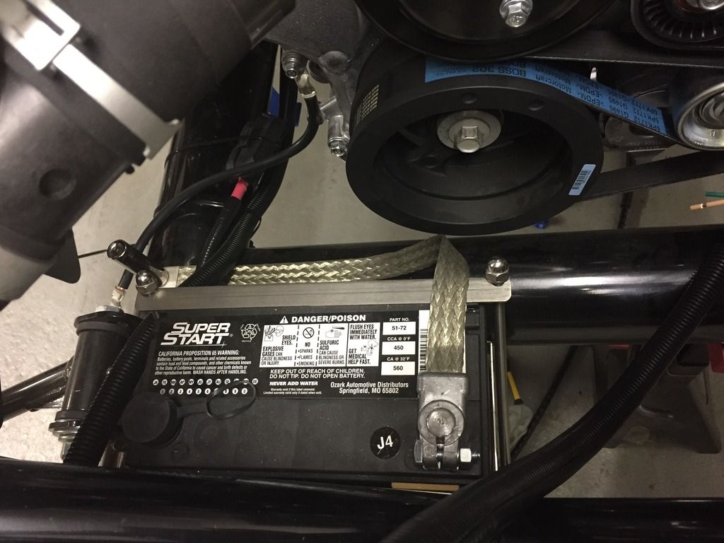
    I noticed you are going with the Breeze battery box up front. I took a picture to show you my rough in. Box is mounted and just trying to figure out where to put the main fuse and lines.


    You are a bit ahead of me routing but maybe the other pictures can be of some use. Thanks

    Jeremiah
    Last edited by jcjorgensen; 12-01-2015 at 07:34 PM.

  5. #5
    Junior Member
    Join Date
    Dec 2013
    Posts
    28
    Post Thanks / Like
    The link to the new instructions, although to be honest I haven't seen much change.

    http://www.factoryfive.com/wp-conten...roadster-O.pdf

  6. #6
    2bking's Avatar
    Join Date
    Jul 2013
    Location
    Garland, Texas
    Posts
    799
    Post Thanks / Like
    Quote Originally Posted by edwardb View Post
    Blunt Lead 3 - Starter Motor Request (Light Blue) connect to the RF Lt Blue EFI Crank Wire. This wire correctly provides +12V when the ignition switch is in the start position. Note you could connect directly to the ignition switch, but using the loose lead would be easier IMO. Note also in this case clutch safety switch connections and the starter solenoid feeds from the RF harness are not used. Those connections are downstream from the EFI Crank Wire and not needed. The Coyote controls pack provides the safety interlock and the starter solenoid feeds directly through the PCM.
    I have no issue with the description but just to be clear, the Starter Motor Request feeds to the PCM as a control circuit but doesn't have the high amperage capacity to actually energize the solenoid. When the PCM sees +12V on the light blue wire and all the interlocks are satisfied, it grounds the Start Relay coil in the PDB to send the high current +12V to the starter solenoid. Connecting the light blue wire to the starter solenoid would be a mistake.
    King
    Roadster #8127, ordered 7/12/13, received 9/11/13
    http://thefactoryfiveforum.com/showt...4-Coyote-Build

  7. #7
    Senior Member edwardb's Avatar
    Join Date
    Feb 2011
    Location
    Lake Orion, Michigan
    Posts
    10,576
    Post Thanks / Like
    Quote Originally Posted by 2bking View Post
    I have no issue with the description but just to be clear, the Starter Motor Request feeds to the PCM as a control circuit but doesn't have the high amperage capacity to actually energize the solenoid. When the PCM sees +12V on the light blue wire and all the interlocks are satisfied, it grounds the Start Relay coil in the PDB to send the high current +12V to the starter solenoid. Connecting the light blue wire to the starter solenoid would be a mistake.
    Thanks for the clarification. Not the best description on my part. I only meant the Coyote PCM controls the starting circuit, but you are correct the actual voltage to energize the starter solenoid is through the power distribution box (PDB). For the 2015 setup, the starting circuit is through a 40 amp relay (R3). More than up to the task.
    Build 1: Mk3 Roadster #5125. Sold 11/08/2014. Build 2: Mk4 Roadster #7750. Sold 04/10/2017. Build Thread
    Build 3: Mk4 Roadster 20th Anniversary #8674. Sold 09/07/2020. Build Thread and Video. Build 4: Gen 3 Type 65 Coupe #59. Gen 3 Coyote. Legal 03/04/2020. Build Thread and Video
    Build 5: 35 Hot Rod Truck #138. LS3 and 4L65E auto. Rcvd 01/05/2021. Legal 04/20/2023. Build Thread. Sold 11/9/2023.

  8. #8
    Senior Member edwardb's Avatar
    Join Date
    Feb 2011
    Location
    Lake Orion, Michigan
    Posts
    10,576
    Post Thanks / Like
    Quote Originally Posted by jcjorgensen View Post
    You are a bit ahead of me routing but maybe the other pictures can be of some use. Thanks Jeremiah
    Looks to me like you're well ahead of me! I'm just mocking up right now and will soon have the engine back out to powder coat and install all the panels, finalize wiring, run fuel and brake lines, etc. Your pictures are a great help! I too was planning to strip the main harness back to the PDB mainly for the starter lead. I was thinking of just sending the fan lead forward right from the PS side since I will have another convolute there for front fog/running lights. But your idea is a good one as well. Assuming the Breeze box fits with the other stuff I'm installing, which I think it will and your pictures support, I will run the primary power feed just like I did on my last build to a master disconnect and get the Coyote PDB power feed from there.


    Thanks for the link to the most recent Coyote installation instructions. Quick review shows no relevant changes for the 2015 setup. The main thing I saw was they deleted all the oil filter relocation instructions and stated which oil filter to use in the stock location. Something many of us are doing anyway. Keep us posted, and I will do the same in my build thread.
    Build 1: Mk3 Roadster #5125. Sold 11/08/2014. Build 2: Mk4 Roadster #7750. Sold 04/10/2017. Build Thread
    Build 3: Mk4 Roadster 20th Anniversary #8674. Sold 09/07/2020. Build Thread and Video. Build 4: Gen 3 Type 65 Coupe #59. Gen 3 Coyote. Legal 03/04/2020. Build Thread and Video
    Build 5: 35 Hot Rod Truck #138. LS3 and 4L65E auto. Rcvd 01/05/2021. Legal 04/20/2023. Build Thread. Sold 11/9/2023.

  9. #9
    Senior Member edwardb's Avatar
    Join Date
    Feb 2011
    Location
    Lake Orion, Michigan
    Posts
    10,576
    Post Thanks / Like
    Quote Originally Posted by jcjorgensen View Post
    Stole your location for where to mount the PCM although I don't have a box break so I went a more simple route and re-purposed some of the old sheet metal since I went with the 2bking sheet metal mod.
    One other quick comment. Not sure how much you stole my location, since that's about the only place it will go with the provided cable lengths... But just FYI, I don't have a box brake. Sometimes wish I did, but haven't been able to justify the cost. I use a pretty cheap and simple 30 inch brake from Harbor Freight. http://www.harborfreight.com/30-in-b...ake-61791.html. It definitely has its limits. But for simple stuff and the relatively thin materials we use, it gets the job done. The PCM mount from my build thread was bent using this tool. Have made a bunch of other parts, including the PS sheet metal mods on my last build.
    Build 1: Mk3 Roadster #5125. Sold 11/08/2014. Build 2: Mk4 Roadster #7750. Sold 04/10/2017. Build Thread
    Build 3: Mk4 Roadster 20th Anniversary #8674. Sold 09/07/2020. Build Thread and Video. Build 4: Gen 3 Type 65 Coupe #59. Gen 3 Coyote. Legal 03/04/2020. Build Thread and Video
    Build 5: 35 Hot Rod Truck #138. LS3 and 4L65E auto. Rcvd 01/05/2021. Legal 04/20/2023. Build Thread. Sold 11/9/2023.

  10. #10
    Junior Member
    Join Date
    Dec 2013
    Posts
    28
    Post Thanks / Like
    Pretty exciting day today! I achieved full power on to the chassis harness and control pack. Nothing melted or popped which is always a plus!!! Fuel pump came on as requested and was able to energize the starter solenoid lead. I eliminated the remote starter solenoid and just went with the solenoid attached to the mini starter. The new control pack comes with two clutch safety switches but once I fused the RF safety switch wires and did the same with the top control pack clutch switch wires, the solenoid lead energized, so not sure if the bottom clutch switch does anything. Will likely have to wait until I get the motor back in and try to figure it out.

    The PDB relays functioned as they should and all in all, very happy to get to this point. I have been dreading completing the wiring but I have to say that integrating the Ford control pack with the RF wiring was painless, especially if we can delete the speed dial but more to come on that as I do not have the answer yet, although traffic on the forum states we can on the 2015 pack.

    Will add some pictures later once I get everything cleaned up.

  11. #11
    Senior Member edwardb's Avatar
    Join Date
    Feb 2011
    Location
    Lake Orion, Michigan
    Posts
    10,576
    Post Thanks / Like
    Excellent news and progress! Ford Racing technical support told me the speed dial is not needed for the 2015-2016 control pack. He said he confirmed it with engineering. He also said he's "pretty sure" the bottom clutch switch (the one that closes when you start pushing the clutch down) is part of the solution, e.g. letting the PCM know the driveline is disconnected and help prevent the stalling condition. Personally, I wouldn't take a chance. Install it.

    Two questions. Can you describe how you connected the various blunt wires compared to how I listed in post #3? Also, did you have the same problem I did, e.g. the provided O2 sensors didn't match the O2 sensor plugs on the engine harness? If so, is it resolved?
    Build 1: Mk3 Roadster #5125. Sold 11/08/2014. Build 2: Mk4 Roadster #7750. Sold 04/10/2017. Build Thread
    Build 3: Mk4 Roadster 20th Anniversary #8674. Sold 09/07/2020. Build Thread and Video. Build 4: Gen 3 Type 65 Coupe #59. Gen 3 Coyote. Legal 03/04/2020. Build Thread and Video
    Build 5: 35 Hot Rod Truck #138. LS3 and 4L65E auto. Rcvd 01/05/2021. Legal 04/20/2023. Build Thread. Sold 11/9/2023.

  12. #12
    Junior Member
    Join Date
    Dec 2013
    Posts
    28
    Post Thanks / Like
    Edward, reviewed your post (#3) and compared that to both the FFR instructions and the Ford Racing instructions just to be sure. Nothing more than striping off some insulation and soldering the control pack to the correct RF lead. Wiring is not my strength so I appreciate you and 2bking jumping in and clarifying. As for the O2 sensor connectors/plugs, they matched right up luckily and I did not have the same problem you did. I have not checked the O2 leads for length but appears the DS will be long enough but I am concerned that the PS lead will not be since it comes off the top and back side of the engine.

    Ran out of time today to get some pictures taken as I was racing to finish up powder coating the PCM sheetmetal but will get them up tomorrow. Shooting to get the motor back in this week and tentatively scheduling a first start for next Sunday if all goes well! Fingers crossed.

  13. #13
    Junior Member
    Join Date
    Dec 2013
    Posts
    28
    Post Thanks / Like
    Motor is back in. Verified that both O2 leads are long enough but as mentioned, the passenger is just long enough. It would be nice if it were longer so one could route it in a more attractive manner. Right now, it is straight from the harness to the O2 bung and doesn't look the best.

  14. #14
    Senior Member edwardb's Avatar
    Join Date
    Feb 2011
    Location
    Lake Orion, Michigan
    Posts
    10,576
    Post Thanks / Like
    Quote Originally Posted by jcjorgensen View Post
    Motor is back in. Verified that both O2 leads are long enough but as mentioned, the passenger is just long enough. It would be nice if it were longer so one could route it in a more attractive manner. Right now, it is straight from the harness to the O2 bung and doesn't look the best.
    Pretty normal to need extensions, and then can be routed in an acceptable manner. The previous controls pack also often required extensions.
    Build 1: Mk3 Roadster #5125. Sold 11/08/2014. Build 2: Mk4 Roadster #7750. Sold 04/10/2017. Build Thread
    Build 3: Mk4 Roadster 20th Anniversary #8674. Sold 09/07/2020. Build Thread and Video. Build 4: Gen 3 Type 65 Coupe #59. Gen 3 Coyote. Legal 03/04/2020. Build Thread and Video
    Build 5: 35 Hot Rod Truck #138. LS3 and 4L65E auto. Rcvd 01/05/2021. Legal 04/20/2023. Build Thread. Sold 11/9/2023.

  15. #15
    Junior Member
    Join Date
    Dec 2013
    Posts
    28
    Post Thanks / Like
    Completed the first start and hopefully my issues help someone else with the new pack. Video here https://www.youtube.com/watch?v=0OPzhN7-nbo

    Issue 1. Throttle (electronic drive by wire) didn't work on first start. The reason, absence mindedness. If you have already hooked up your battery to your system (PCM/PDB sees power) and then plug in the connection to your throttle, your throttle may not work. It worked on my second start

    Issue 2. Following the Ford control pack instructions for Setup B, referencing Edwards post (#3) Blunt Lead 16 - Key On 12V/10A (Yellow) was not needed for me. When I completed the first start and went to shut the motor down, it would not shut down until I went from On, CCW past off and finally would kill the engine when I was in the farthest CCW ACC spot on the ignition switch.

    Got out the multimeter and started to test again. What was weird is the ignition switch checked out by itself (no continuity between +12V and off position) and would check out again with leads attached before reconnecting the battery. As soon as I hooked up the battery and rotated the ignition switch to On, the PDB relays would energize and the Blunt Lead 16 - Key On 12V/10A (Yellow) would have power regardless of whether the ignition switch was in On or ACC. This was after several hours of testing leads, disconnecting harness connections and validating the RF fuse box. Literally pulling my hair out. The kicker, I was only checking the connection at the ignition switch not where the Blunt Lead 16 - Key On 12V/10A (Yellow) tied in.

    I even went as far as trying to hookup the Blunt Lead 16 - Key On 12V/10A (Yellow) to both the RF orange and brown wires (ACC and On connections) just to validate what was going on. Since both of these see +12v, there was little risk of damaging anything as the PCM/PDB would just think it was either in ACC or On. You experienced guys are probably cringing right now. Yep the motor would not shut off! Disconnecting the battery didn't help as now the alternator was providing enough juice at idle to keep the motor running. I had to physically cut the Blunt Lead 16 - Key On 12V/10A (Yellow) to kill the motor. But that was the point that I realized that the Blunt Lead 16 - Key On 12V/10A (Yellow) had power regardless of which lead (Acc or On) I connected it to. And since both of these see power through the ignition switch I was never able to isolate it or THOUGHT about isolating it.

    Summary and your results may vary. For Setup B (using an ignition switch), I do not need the Blunt Lead 16 - Key On 12V/10A (Yellow) at all.


    I will likely go back, pull the PDB so I can get to the back side (bottom side) so I can find out why the Blunt Lead 16 - Key On 12V/10A (Yellow) has power whenever the ignition switch is on On or ACC and has power while the engine is running. But for now, trying to get everything buttoned up so I can go kart it!
    Last edited by jcjorgensen; 12-31-2015 at 03:54 PM.

  16. #16
    Senior Member edwardb's Avatar
    Join Date
    Feb 2011
    Location
    Lake Orion, Michigan
    Posts
    10,576
    Post Thanks / Like
    Quote Originally Posted by jcjorgensen View Post
    Completed the first start and hopefully my issues help someone else with the new pack. Video here https://www.youtube.com/watch?v=0OPzhN7-nbo

    Issue 1. Throttle (electronic drive by wire) didn't work on first start. The reason, absence mindedness. If you have already hooked up your battery to your system (PCM/PDB sees power) and then plug in the connection to your throttle, your throttle may not work. It worked on my second start

    Issue 2. Following the Ford control pack instructions for Setup B, referencing Edwards post (#3) Blunt Lead 16 - Key On 12V/10A (Yellow) was not needed for me. When I completed the first start and went to shut the motor down, it would not shut down until I went from On, CCW past off and finally would kill the engine when I was in the farthest CCW ACC spot on the ignition switch.

    Got out the multimeter and started to test again. What was weird is the ignition switch checked out by itself (no continuity between +12V and off position) and would check out again with leads attached before reconnecting the battery. As soon as I hooked up the battery and rotated the ignition switch to On, the PDB relays would energize and the Blunt Lead 16 - Key On 12V/10A (Yellow) would have power regardless of whether the ignition switch was in On or ACC. This was after several hours of testing leads, disconnecting harness connections and validating the RF fuse box. Literally pulling my hair out. The kicker, I was only checking the connection at the ignition switch not where the Blunt Lead 16 - Key On 12V/10A (Yellow) tied in.

    I even went as far as trying to hookup the Blunt Lead 16 - Key On 12V/10A (Yellow) to both the RF orange and brown wires (ACC and On connections) just to validate what was going on. Since both of these see +12v, there was little risk of damaging anything as the PCM/PDB would just think it was either in ACC or On. You experienced guys are probably cringing right now. Yep the motor would not shut off! Disconnecting the battery didn't help as now the alternator was providing enough juice at idle to keep the motor running. I had to physically cut the Blunt Lead 16 - Key On 12V/10A (Yellow) to kill the motor. But that was the point that I realized that the Blunt Lead 16 - Key On 12V/10A (Yellow) had power regardless of which lead (Acc or On) I connected it to. And since both of these see power through the ignition switch I was never able to isolate it or THOUGHT about isolating it.

    Summary and your results may vary. For Setup B (using an ignition switch), I do not need the Blunt Lead 16 - Key On 12V/10A (Yellow) at all.


    I will likely go back, pull the PDB so I can get to the back side (bottom side) so I can find out why the Blunt Lead 16 - Key On 12V/10A (Yellow) has power whenever the ignition switch is on On or ACC and has power while the engine is running. But for now, trying to get everything buttoned up so I can go kart it!
    Good stuff and really appreciate the updates! One of these days I'll get there. But it's going to some months at least. Especially glad to hear the DBW is working. You're right. A couple of the things you mentioned made me cringe a little bit. But I'm still confused about that yellow blunt lead 16. First the instructions are very clear it goes on the ACC connection of the switch, not the ON position. So I guess I wouldn't be trying anything but that. But I tend to agree it shouldn't make a difference. I too just did a continuity test on the ignition switch. With no wires attached so it's just the internal connections of the switch itself. In the ON position, you're right, both IG and ACC would receive 12 volts. In the ACC position, only ACC would receive 12 volts. But in the OFF position, neither receive 12 volts so in the off position why would the engine keep running? You said you cut the wire. That's the same thing as the OFF position. Something doesn't seem right. Whatever you're attaching that yellow wire to apparently still has 12 volts even with the key off. That's probably something I would check.

    Having said all that, I have to agree the purpose of the yellow wire is not clear to me either. The instructions for setup B only say "Connect to the ‘Accessory’ output node of ignition cylinder so that 12 volts is provided when key is in ‘Accessory/Run’ mode with engine off." But it doesn't say why. Looking at setup A, where the instructions say not to use the yellow wire, it's obvious the system only needs the the light green ignition sense wire to know it's time to run, and the light blue wire to trigger the starter. Without the yellow wire, setup B ends up doing the same thing. So maybe you're right the yellow wire isn't needed. Might be a good question for Ford Racing tech support.
    Last edited by edwardb; 12-31-2015 at 05:58 PM.
    Build 1: Mk3 Roadster #5125. Sold 11/08/2014. Build 2: Mk4 Roadster #7750. Sold 04/10/2017. Build Thread
    Build 3: Mk4 Roadster 20th Anniversary #8674. Sold 09/07/2020. Build Thread and Video. Build 4: Gen 3 Type 65 Coupe #59. Gen 3 Coyote. Legal 03/04/2020. Build Thread and Video
    Build 5: 35 Hot Rod Truck #138. LS3 and 4L65E auto. Rcvd 01/05/2021. Legal 04/20/2023. Build Thread. Sold 11/9/2023.

  17. #17
    Junior Member
    Join Date
    Dec 2013
    Posts
    28
    Post Thanks / Like
    Quote Originally Posted by edwardb View Post
    First the instructions are very clear it goes on the ACC connection of the switch, not the ON position.
    I did a terrible job explaining that and had it hooked up according to the instructions originally. But to provide a bit more background on the yellow wire; with the lead 16 (yellow) not hooked to anything at all, simply hanging off of the control pack connection, these are the results I get.

    With the key in the On position, there is 12v coming from the yellow wire. This is what throws me as there is 12v coming back through the PDB to the Yellow wire. With the Ford Racing instructions, I understood it that the key/ignition would provide power to the yellow wire, not the other way around.

    When the key is in ACC, there is power at the ignition but not 12v on the yellow wire. Thus the ignition switch is now providing the 12v to the yellow wire.

    So with that being said, if the yellow wire is hooked to ACC, the PCM/PDB sees 12v at the yellow lead whether in ACC or On.

  18. #18
    Senior Member edwardb's Avatar
    Join Date
    Feb 2011
    Location
    Lake Orion, Michigan
    Posts
    10,576
    Post Thanks / Like
    Quote Originally Posted by jcjorgensen View Post
    I did a terrible job explaining that and had it hooked up according to the instructions originally. But to provide a bit more background on the yellow wire; with the lead 16 (yellow) not hooked to anything at all, simply hanging off of the control pack connection, these are the results I get.

    With the key in the On position, there is 12v coming from the yellow wire. This is what throws me as there is 12v coming back through the PDB to the Yellow wire. With the Ford Racing instructions, I understood it that the key/ignition would provide power to the yellow wire, not the other way around.

    When the key is in ACC, there is power at the ignition but not 12v on the yellow wire. Thus the ignition switch is now providing the 12v to the yellow wire.

    So with that being said, if the yellow wire is hooked to ACC, the PCM/PDB sees 12v at the yellow lead whether in ACC or On.
    Your explanation was OK. I understood that aspect, but limited my comments to wondering why the yellow wire had to be disconnected vs. having the switch in the off position. I agree the instructions from Ford Racing seem to say that the key/ignition switch is providing the 12 volts to the yellow wire vs. the other way around. The fact that you can measure 12 volts on the yellow wire from the PCM could be normal and maybe very low current. Or it could be an indication of something else. I certainly don't know. For me the main question remains what is the purpose of the yellow wire? It's clearly not needed for the engine to run, witness your experience plus the instructions for setup A. Is there some reason the designers of this systems thought it was important for the PCM to "know" the ignition switch was in the ACC position? Maybe to not run the fuel pump or even the ignition system itself? At this point none of us knows, and frankly for these builds ACC isn't that important. I rarely if ever use it on my other builds, plus I'm planning to have an under dash fuel pump switch and maybe even an ignition cut-off switch. For security purposes plus there are times you have the key on and just don't want those things running, e.g. during construction, troubleshooting, etc. I'm not going to call Ford Racing support about this question alone, but if I need to call them about something else will probably ask.

    Separate questions. Just curious. Did you do any kind of oil priming step before your first start? Also, were you able to figure out a way to tap one of the coil wires and get your tach running?
    Build 1: Mk3 Roadster #5125. Sold 11/08/2014. Build 2: Mk4 Roadster #7750. Sold 04/10/2017. Build Thread
    Build 3: Mk4 Roadster 20th Anniversary #8674. Sold 09/07/2020. Build Thread and Video. Build 4: Gen 3 Type 65 Coupe #59. Gen 3 Coyote. Legal 03/04/2020. Build Thread and Video
    Build 5: 35 Hot Rod Truck #138. LS3 and 4L65E auto. Rcvd 01/05/2021. Legal 04/20/2023. Build Thread. Sold 11/9/2023.

  19. #19
    2bking's Avatar
    Join Date
    Jul 2013
    Location
    Garland, Texas
    Posts
    799
    Post Thanks / Like
    Quote Originally Posted by edwardb View Post
    Separate questions. Just curious. Did you do any kind of oil priming step before your first start?
    I didn't on mine. It's run at the factory so it has oil everywhere. My first start was actually while spinning the motor with fuel pump disconnected to get oil pressure. The residual fuel pressure was enough to bring it to life and the oil pressure came up before I could hit the off button.
    King
    Roadster #8127, ordered 7/12/13, received 9/11/13
    http://thefactoryfiveforum.com/showt...4-Coyote-Build

  20. #20
    Junior Member
    Join Date
    Dec 2013
    Posts
    28
    Post Thanks / Like
    Quote Originally Posted by edwardb View Post
    Separate questions. Just curious. Did you do any kind of oil priming step before your first start? Also, were you able to figure out a way to tap one of the coil wires and get your tach running?
    I took the same route King did. I was actually surprised it shipped with oil and then my first step was to drain it all out to replace the pan! I researched different ways to try to prime it but in the end just cranked the engine over prior to hooking up the fuel lines. Pressure came up quickly so I proceeded forward.

    As for the tach I didn't have any luck. I have the Autometer Ultra-Lites and used your suggestion on tying into the #7 cylinder. The tach needle would just bounce around at ~500 RPM regardless of what the engine was doing. I have the Autometer tach adapter on order and will see if that helps.
    https://www.autometer.com/media/2650-561X.pdf

  21. #21
    Junior Member
    Join Date
    Dec 2013
    Posts
    28
    Post Thanks / Like
    It has been a while since I have updated the thread. I am now registered and have put about 100 miles on it. Removed the body yesterday to finish up a couple of loose ends and begin to check all the nuts and bolts to insure nothing is backing off. Not sure how most do it but even though I am registered, all my sheet metal is still cleco'd and the wiring wasn't complete. So the body is off so I can begin to complete it before off to paint.

    So, the control pack. Two things to update.

    1. The clutch bottom switch (CBT) page 4 of the control pack install guide. https://performanceparts.ford.com/do...-6017-504V.pdf I didn't final install this but to enable getting this switch to work for me to start the engine, I ended up taking the upper portion (the portion where the plug inserts into the switch) and just installing it 180 deg or clocked in an 180 deg in relation to its original orientation. That worked to date but did notice while sitting at a stop light, if you counted to about 7, the engine RPM would raise about 100 rpm and stay that way until you took off. I believe this makes sense, the PCM is seeing the CBT or clutch depressed all the time while the CTT (clutch top switch) stays open, signaling that the clutch is never depressed. Imagine this is confusing the PCM. So while the body is off I am converting to a signal switch and using another brake light switch configured to provide the open/closed signal to the PCM. Will report out if that fixes the high idle after sitting phenomenon. Since I am converting two switches to one, thus raising the resistance would drop the current so relatively confident I will not damage anything in the PCM. Fingers crossed!!

    2. The second issue I ran across. My tach hasn't worked since day one. I used edwardB's recommendation to connect to the #7 cylinder. To enable my Ultra-Lite tach to work, I had to purchase the autometer tach adapter. http://www.autometer.com/tach-adapter.html Once I purchased this and hooked up to the #7 cylinder, it did not read while hooked to the yellow COP wire. I actually had to hook it up to the purple wire going to #7. Still want to do some more troubleshooting as the tach needle bounces more than I would like to see.

    Hope this helps those installing the new control pack.

  22. #22
    Senior Member edwardb's Avatar
    Join Date
    Feb 2011
    Location
    Lake Orion, Michigan
    Posts
    10,576
    Post Thanks / Like
    Quote Originally Posted by jcjorgensen View Post
    It has been a while since I have updated the thread. I am now registered and have put about 100 miles on it. Removed the body yesterday to finish up a couple of loose ends and begin to check all the nuts and bolts to insure nothing is backing off. Not sure how most do it but even though I am registered, all my sheet metal is still cleco'd and the wiring wasn't complete. So the body is off so I can begin to complete it before off to paint.

    So, the control pack. Two things to update.

    1. The clutch bottom switch (CBT) page 4 of the control pack install guide. https://performanceparts.ford.com/do...-6017-504V.pdf I didn't final install this but to enable getting this switch to work for me to start the engine, I ended up taking the upper portion (the portion where the plug inserts into the switch) and just installing it 180 deg or clocked in an 180 deg in relation to its original orientation. That worked to date but did notice while sitting at a stop light, if you counted to about 7, the engine RPM would raise about 100 rpm and stay that way until you took off. I believe this makes sense, the PCM is seeing the CBT or clutch depressed all the time while the CTT (clutch top switch) stays open, signaling that the clutch is never depressed. Imagine this is confusing the PCM. So while the body is off I am converting to a signal switch and using another brake light switch configured to provide the open/closed signal to the PCM. Will report out if that fixes the high idle after sitting phenomenon. Since I am converting two switches to one, thus raising the resistance would drop the current so relatively confident I will not damage anything in the PCM. Fingers crossed!!

    2. The second issue I ran across. My tach hasn't worked since day one. I used edwardB's recommendation to connect to the #7 cylinder. To enable my Ultra-Lite tach to work, I had to purchase the autometer tach adapter. http://www.autometer.com/tach-adapter.html Once I purchased this and hooked up to the #7 cylinder, it did not read while hooked to the yellow COP wire. I actually had to hook it up to the purple wire going to #7. Still want to do some more troubleshooting as the tach needle bounces more than I would like to see.

    Hope this helps those installing the new control pack.
    Thanks for the update. Good to hear a 2015 Coyote is running and working. Comments about your two points:

    1. I'm not 100% clear about what you're describing. Sounds like you rigged the clutch bottom switch to be always closed? It does have to be closed in order for the PCM to allow a start. But still closed while the clutch top switch is open (meaning the clutch not pressed down) isn't normal so you're guessing this is confusing the PCM? Could be. I'm not getting your two switches in one comments. Simple question. Why not wire the switches the way they're supposed to work? That's what I'm planning to do. I already have a top switch installed using a similar bracket and switch as the FF recommended brake light installation. I haven't done it yet, but planning to rig up a bottom switch that actuates when the clutch pedal is depressed. I'm not sure the Ford supplied switch will be best, and it's quite large and oddly shaped. I'm thinking of using a pretty normal roller micro switch rigged into the Wilwood pedal box. Still TBD. Comments?

    2. According to the Speedhut instructions, I only need a single wire for the tach, and it has to be the signal one (yellow in the case of #7) and not the common one (orange). Obviously I'm hopeful it works as they describe. Sounds like Autometer is quite different.
    Last edited by edwardb; 03-22-2016 at 12:03 PM.
    Build 1: Mk3 Roadster #5125. Sold 11/08/2014. Build 2: Mk4 Roadster #7750. Sold 04/10/2017. Build Thread
    Build 3: Mk4 Roadster 20th Anniversary #8674. Sold 09/07/2020. Build Thread and Video. Build 4: Gen 3 Type 65 Coupe #59. Gen 3 Coyote. Legal 03/04/2020. Build Thread and Video
    Build 5: 35 Hot Rod Truck #138. LS3 and 4L65E auto. Rcvd 01/05/2021. Legal 04/20/2023. Build Thread. Sold 11/9/2023.

  23. #23
    Junior Member
    Join Date
    Dec 2013
    Posts
    28
    Post Thanks / Like

    Update

    Quote Originally Posted by edwardb View Post
    Thanks for the update. Good to hear a 2015 Coyote is running and working. Comments about your two points:

    1. I'm not 100% clear about what you're describing. Sounds like you rigged the clutch bottom switch to be always closed? It does have to be closed in order for the PCM to allow a start. But still closed while the clutch top switch is open (meaning the clutch not pressed down) isn't normal so you're guessing this is confusing the PCM? Could be. I'm not geeting your two switches in one comments. Simple question. Why not wire the switches the way they're supposed to work? That's what I'm planning to do. I already have a top switch installed using a similar bracket and switch as the FF recommended brake light installation. I haven't done it yet, but planning to rig up a bottom switch that actuates when the clutch pedal is depressed. I'm not sure the Ford supplied switch will be best, and it's quite large and oddly shaped. I'm thinking of using a pretty normal roller micro switch rigged into the Wilwood pedal box. Still TBD. Comments?

    2. According to the Speedhut instructions, I only need a single wire for the tach, and it has to be the signal one (yellow in the case of #7) and not the common one (orange). Obviously I'm hopeful it works as they describe. Sounds like Autometer is quite different.
    Great comments.

    1. On the two clutch switches, I have gone back and forth for several months trying to determine the best way to configure them. What I don't understand is why the need for both switches to perform the same task. Both are normally open and as I read it (for the hundredth time it seems) they both close when the clutch is depressed. I have played around with trying to mount them but two things have me concerned. They are both rather bulky and don't lend themselves to easy mounting but it can be done. Second is that I want to mount them from below so that better access is available in the future. So I played around with mounting both of them below in a similar fashion to how the brake light switch is mounted. During that process I got the idea of just using a brake light switch and combining the electrical leads so one switch is used in lieu of two. Jury is out on whether this will be a good idea or not. I did get it mounted, started the engine and everything acts as it should. Engine will not start without the clutch depressed, regardless of how the RF harness is configured. Since the body is off, I have not figured out whether it fixes the high idle phenomenon at a stop light. Will post more in a couple of weeks once I have the interior finalized and body back together.

    2. The Autometer Ultra Lite tach only needs a single wire to provide the signal as well. On my #7 cylinder, I had a yellow and a purple wire for the COP and did not see an orange. I tried hooking my tach up to both wires and only received the signal from the purple wire. Not sure how the Speedhut works and my Autometer would not work without the additional tach adapter box, also from Autometer. In this case I believe the different brands leads to different solutions so I wanted to provide what worked for me. Hopefully you don't run into any issues.

  24. #24
    Senior Member edwardb's Avatar
    Join Date
    Feb 2011
    Location
    Lake Orion, Michigan
    Posts
    10,576
    Post Thanks / Like
    Quote Originally Posted by jcjorgensen View Post
    On the two clutch switches, I have gone back and forth for several months trying to determine the best way to configure them. What I don't understand is why the need for both switches to perform the same task. Both are normally open and as I read it (for the hundredth time it seems) they both close when the clutch is depressed.
    That's partly true. But actually the top switch would close with just the slightest clutch movement, while the bottom switch wouldn't close until the clutch is all the way down. From a safety standpoint, makes sense the bottom switch would be used as a starter interlock, e.g. when the clutch is fully depressed. But regarding the two working together, I think it's likely the designers want to differentiate between the two clutch positions. When I asked Ford Racing tech support about whether the speed dial was needed for the new 2015 control pack, they responded no and said hardware and software changes had been made to solve the idle/stall issue of the previous crate control pack. He specifically cited the clutch switches as part of that solution. My takeaway is to figure out a way to make them work as designed. I'll be interested in what you come up with, and how it affects the engine's running characteristics.
    Build 1: Mk3 Roadster #5125. Sold 11/08/2014. Build 2: Mk4 Roadster #7750. Sold 04/10/2017. Build Thread
    Build 3: Mk4 Roadster 20th Anniversary #8674. Sold 09/07/2020. Build Thread and Video. Build 4: Gen 3 Type 65 Coupe #59. Gen 3 Coyote. Legal 03/04/2020. Build Thread and Video
    Build 5: 35 Hot Rod Truck #138. LS3 and 4L65E auto. Rcvd 01/05/2021. Legal 04/20/2023. Build Thread. Sold 11/9/2023.

  25. #25
    Junior Member
    Join Date
    Apr 2014
    Posts
    12
    Post Thanks / Like
    Hello everyone,
    I had the same problem with the Ultralite Tach and 2016 Coyote.
    Did a lot of research and this was how I did it based on FFR, Autometer, and Ford racing:

    http://thefactoryfiveforum.com/showt...051#post254051

    Hope this helps!
    Jon

Posting Permissions

  • You may not post new threads
  • You may not post replies
  • You may not post attachments
  • You may not edit your posts
  •  

Stewart Transport

Visit our community sponsor