-
03-15-2020, 10:32 AM
#681
Senior Member


Originally Posted by
jforand

Very nice looking! I love how simple and clean it is. So you are saying that the oil pump in your transmission had a tap into the discharge and that it was is going up to your cooler? That is super slick. Do you have any insight as to how much flow can be safely diverted? I remember talking about your scavenger pump you had to slow down which I guess was on your 5 speed. My first thought on these pics was how do you pick up oil half way up the case? A 'free' oil cooler, so much easier than adding a pump with the plumbing and wiring.
Its not that there is tap, its even better than that! In the pre 08 transmissions with an internal oil pump, 100% of the fluid from the pump exits the case and is routed through an external steel line. It re-enters the case near the front. In the pic below you can see the external line pointed to by red arrows. So hooking up an external cooler is super simple. Just remove the external line and replace it with the correct sized banjo bolts and plum in your cooler.

Originally Posted by
jforand
I have never use that style of AN connector. It looks like barbs, but I do not see anything holding the hose onto the barbs like a compression ring....Are they pressure rated or are you just banking on very low pressures?
The connectors are called push lok. They are great, push on and reusable. They are rated for 400 psi, no compression ring needed, I use them for everything. You do need the correct push lock type hose though. Summit Racing has a great selection.
Originally Posted by
jforand
Also in looking back at your open trans picks I do see the circular oil router piece in the left over output shaft race. It looks like that is the same idea as the piece that is behind the gear bolted into the tail housing. It puts oil into the shaft center. The lower one for the pinion shaft we both cut off handles the needle bearings (no longer in play). I think my output shaft was solid but I'm thinking your must have had something on it with a bleed hole or two. I looks like that is probably unnecessary now unless you think the size of the orifice actually holds some back pressure providing flow elsewhere. I would think behind it looks very similar to the same size hole, which is what mine has.
My shaft was hollow for oil flow. But, behind that plastic ring there were drilled oil passages that diverted flow to the left and right sides. Yours did not seem to have those passages. If I removed the diverter and the race the oil flow would have never gotten to those left and right passages so I left it in.
These are some of the reasons people prefer the older 6 speeds. The built in pump and ease of adding a cooler make it a better trans for hard use.
-
03-15-2020, 07:11 PM
#682
Oh heck yeah, easiest oil cooler ever. You don’t even have to sweat reducing flow. You simply put an exchanger in between the to existing ports. I’m jealous!
-
03-17-2020, 06:50 PM
#683
Senior Member
Final reverse lockout cable

My first cable was a choke cable and had too much internal friction to work. My second cable was a tractor PTO cable. It worked but was large and clunky. My final cable is from McMaster-Carr and is a braided cable like a bicycle brake cable and lever. It works super smooth and the return spring built into the lockout mechanism is more than strong enough to return the lever when you let go of it.
IMG_20200317_164940608.jpg IMG_20200317_164906653.jpg
Hope my early mistakes help someone get there in one step 
-
Post Thanks / Like - 1 Thanks, 2 Likes
 DSR-3
DSR-3 thanked for this post
-
03-17-2020, 08:14 PM
#684
Nice setup.
Man, that shifter is a heck of a lot more robust than the plastic thing in my kit.
-
03-18-2020, 08:05 AM
#685
-
03-18-2020, 02:01 PM
#686
I had a custom length cable made to fit the reverse lockout. The cable was made to mimic what subaru used but longer. I can post the manufacturer of it if anyone is interested. I cut off the OEM 6 speed upper portion of the shifter that includes the reverse lock out ring and welded it onto the FFR provided shifter.
This is the best photo i have of the transmission side at the moment.

and shifter

-
04-14-2020, 04:30 PM
#687
Senior Member
-
Post Thanks / Like - 0 Thanks, 2 Likes
-
04-14-2020, 06:55 PM
#688
Senior Member

-
04-14-2020, 07:41 PM
#689
Senior Member
-
04-14-2020, 10:02 PM
#690
Originally Posted by
Hobby Racer
Are they fixed now?
I can see them.
-
04-15-2020, 12:19 PM
#691
Senior Member
Extending the oil pan
I need to extend my oil pan to fit over my new swing arm oil pump pickup. My design parameters are simple.
- Extend the pan so the swing arm clears the bottom and moves freely
- Keep the bottom of the pan above my diffuser
- Make it as simple as possible
Given the complex and odd shape of the stock pan I decided to keep the mating surface of the stock pan and build on that.
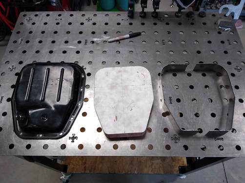
I made a wooden pattern of the pan sides so I could bend up some 16 gauge steel to fit nicely.
IMG_20200406_183151768.jpg IMG_20200415_112330641.jpg IMG_20200415_112708384.jpg
Next I cut the bottom off the stock pan with a 4 1/2 grinder and a cut off wheel. Everything seems to fit up very nicely. Next I need to cut out the new pan bottom out of the sheet of 16 gauge steel and TIG weld it all together.
IMG_20200415_120604811.jpg IMG_20200415_124200388.jpg IMG_20200415_124204068.jpg IMG_20200415_112724332.jpg
-
Post Thanks / Like - 0 Thanks, 3 Likes
-
04-15-2020, 01:24 PM
#692
Senior Member

Some fine surgery with that angle grinder. Very resourceful. I always learn a lot from this forum.
-
04-17-2020, 02:46 PM
#693
Very nice on the pedal stop. Mitch Wright was commenting on his need for a stop as he would over extend and blow out the slave cylinder on the clutch. I imagine this is in my future as well.
Nice camera work! How do you fit those ARMS in the car?
-
04-17-2020, 03:21 PM
#694
Senior Member
Originally Posted by
jforand
How do you fit those ARMS in the car?
Ok, that went right went right over my head. What do you mean?
-
04-19-2020, 04:12 PM
#695
Senior Member
New oil pickup swing-arm
This is my second attempt at an oil pickup swing arm. This version uses a standard shielded ball bearing instead of needle bearings. With this design I was able to make the swing arm a press fit into the bearing race, eliminating any slop that causes binding when it swinging. The arm is made from simple schedule 40 black pipe from Home Depot that has been turned down and press fit into the inner bearing race. The bearing mounting block is machined from an extruded piece of aluminum flat stock.
IMG_20200419_103332814.jpg IMG_20200419_153026054.jpg IMG_20200419_153038547.jpg
Test fitting in the car showed a nice fit and decent swing range. Now I need to finish the pan by welding on a new bottom piece with a drain plug.
IMG_20200419_153209181.jpg IMG_20200419_153231353.jpg IMG_20200419_153224380.jpg
Last edited by Hobby Racer; 04-19-2020 at 04:27 PM.
-
Post Thanks / Like - 1 Thanks, 3 Likes
-
04-20-2020, 08:35 AM
#696

Yes, I love Technology

Very nice - should be "the solution".
-
04-20-2020, 12:03 PM
#697
-
04-20-2020, 12:38 PM
#698
Senior Member
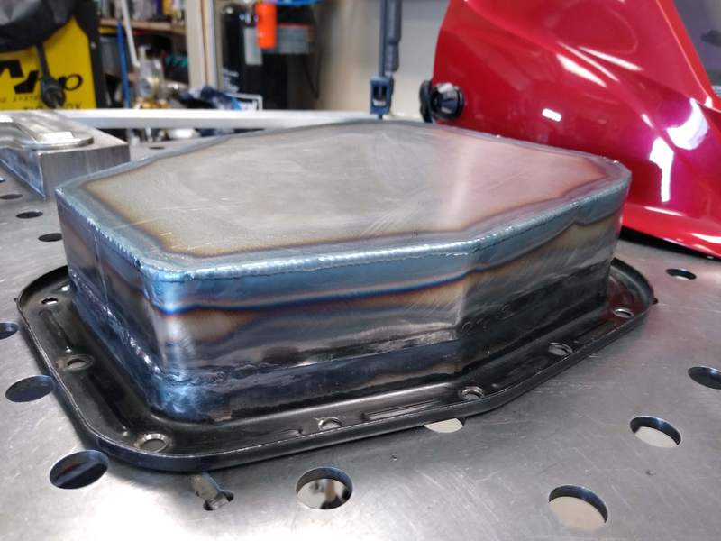
Pan complete
I completed the pan this morning by welding on the bottom piece and adding a drain plug. I have to say, the pulse settings on modern inverter TIG welders are amazing. I welded the bottom without using any filler rod, just dialed in the pulse setting and melted over the corner. It came out excellent. Tonight I will fill it with water and let it sit overnight to check for leaks before painting it.
IMG_20200420_103036756.jpg IMG_20200420_112637728.jpg IMG_20200420_112648020.jpg IMG_20200420_121642790.jpg IMG_20200420_121700183.jpg
Last edited by Hobby Racer; 04-20-2020 at 05:11 PM.
-
Post Thanks / Like - 0 Thanks, 7 Likes
-
04-23-2020, 08:57 AM
#699
HAHA, sorry about going over your head. It has been a few days and I honestly had to go back and figure it back out myself! I was commenting on your above picture in post 678 (the last one) . I am pretty sure I could not take that picture. You either have me really beat on flexibility or have REALLY long arms!
Really beautiful work. I wish I had access to machine shop equipment. I find myself still struggling to determine the best way to cut metal stock....
-
04-23-2020, 09:17 AM
#700
Senior Member
Originally Posted by
jforand
HAHA, sorry about going over your head. It has been a few days and I honestly had to go back and figure it back out myself! I was commenting on your above picture in post 678 (the last one) . I am pretty sure I could not take that picture. You either have me really beat on flexibility or have REALLY long arms!
Three words, removable steering wheel!
Originally Posted by
jforand
Really beautiful work. I wish I had access to machine shop equipment. I find myself still struggling to determine the best way to cut metal stock....
There is really nothing you can't cut with a cheap 4 1/2" angle grinder and a cut off wheel. Better tools might do it faster and or straighter but with patience you can do it with simple cheap tools.
-
04-23-2020, 10:07 AM
#701
IMG_20200419_153209181.jpg IMG_20200419_153231353.jpg IMG_20200419_153224380.jpg
I was wondering about the swing and then you posted these pics. I was thinking that a full 360 swing would be cool as that is what the oil itself is going to be doing. If the pan was square it would facilitate that better with a circle being ideal. I don't believe changing the pan makes a lot of sense, I think you nailed that. The only other thing to facilitate a full 360 swing would be to shorten the arm. The downside of that is the pickup gets further from the front and back of the pan which is not ideal at all.
I'm thinking with the keyboard here a little so forgive me:
1) As the swing arm hits the sides of the pan I see two things potentially happening. 1) Impacting and wear. Over time I can see a wear pattern developing and possibly starting to outwardly dent the pan (death by a thousand paper cuts type thing). You seem to have a a pretty substantial interference angle at this point (versus swinging in at at more of a tangent to the side). As it wears or outwardly dents it will become more tangential. That will lead to potential binding and getting stuck over to a given side. You might want to put a bit of thought into welding in a little perpendicular stop on each side of the pan to keep it from trying to wedge into the side of the pan.
2) It appears to me that you have the arm pointed forward. I was wondering why you picked that orientation? To be clear, there will be a ton of lateral loading and that is what the swing takes care of. I am purely considering the fore/aft loading at his point to pick the best swing arm orientation. At first it seemed natural to me as I believe that you pull more G's under braking than acceleration (at least I do in the Mustang ~2:1). So put the pickup where the oil goes right? Then I kept thinking and I believe that the majority (with respect to time) of the longitudinal G loading will be to the rear. The thought is braking is most extreme and very compressed, whereas, the acceleration is more spread out and time consuming. All of the neutral loading just factors out for this exercise. I think I would give consideration to orienting the pickup in the rear facing direction. Of course, if you had data to say that oil pressure never wavered except under braking then that would change things.
3) You have picked differing materials and are relying on press fits. I am pretty sure that there are interference fits that will be just fine, but I am also certain that too loose could cause problems. Your aluminum piece will grow with heat more than the steel which will work to reduce the interference fit. There is a temperature out there where the bearing will fall out, which would obviously be the end of your engine. You might want to consider fashioning a retaining plate to close off/retain the bearing in your aluminum housing. Just a ring that goes around the pickup tube and has a couple ears that bolt to the aluminum flange. If you really wanted to be ultra safe, you could tack in a small steel collar on the pickup tube just outside the press fit into the bearing that would also be retained should that press fit start to walk on you as well.
Super clean and Super efficient. Just thought I would throw out a few considerations as they are easy to contemplate and incorporate at this stage. If anything is unclear feel free to ask for clarification.
Last edited by jforand; 04-23-2020 at 11:03 AM.
-
04-23-2020, 01:13 PM
#702
Senior Member
Originally Posted by
jforand
1) As the swing arm hits the sides of the pan I see two things potentially happening. 1) Impacting and wear. Over time I can see a wear pattern developing and possibly starting to outwardly dent the pan (death by a thousand paper cuts type thing).
I don't think the arm will swing that violently as it is cushioned by quite a bit of oil and is not that heavy. I will however check on it after a season to see if there are any witness marks being made in the pan. If I find any I will come up with something to limit travel at the extremes.
Originally Posted by
jforand
2) It appears to me that you have the arm pointed forward. I was wondering why you picked that orientation? To be clear, there will be a ton of lateral loading and that is what the swing takes care of. I am purely considering the fore/aft loading at his point to pick the best swing arm orientation. At first it seemed natural to me as I believe that you pull more G's under braking than acceleration (at least I do in the Mustang ~2:1). So put the pickup where the oil goes right? Then I kept thinking and I believe that the majority (with respect to time) of the longitudinal G loading will be to the rear. The thought is braking is most extreme and very compressed, whereas, the acceleration is more spread out and time consuming. All of the neutral loading just factors out for this exercise. I think I would give consideration to orienting the pickup in the rear facing direction. Of course, if you had data to say that oil pressure never wavered except under braking then that would change things.
I do in fact have data to back this up, but the two places I lose oil pressure are under heavy braking and hard cornering. I never lose pressure under acceleration because, like most cars, we do not have enough power to pull real G's in acceleration so there is always plenty of oil around the pickup, no matter where it is in the pan. So it makes the most sense to have the pickup face forward and swing left to right.
Originally Posted by
jforand
3) You have picked differing materials and are relying on press fits. I am pretty sure that there are interference fits that will be just fine, but I am also certain that too loose could cause problems. Your aluminum piece will grow with heat more than the steel which will work to reduce the interference fit. There is a temperature out there where the bearing will fall out, which would obviously be the end of your engine. You might want to consider fashioning a retaining plate to close off/retain the bearing in your aluminum housing. Just a ring that goes around the pickup tube and has a couple ears that bolt to the aluminum flange. If you really wanted to be ultra safe, you could tack in a small steel collar on the pickup tube just outside the press fit into the bearing that would also be retained should that press fit start to walk on you as well.
It might be hard to see in the pics but there is a shelf machined into the aluminum mount that the bearing rests on when pressed into the mount. Once the mount is bolted to the bottom of the oil pump the bearing is trapped and can not come out. The swing arm is steel as is the bearing race its pressed into so they expand at approximately the same rate. However I am still thinking of either staking the top or putting the tiniest of tack welds on it to ensure is can never come out.
-
04-23-2020, 06:57 PM
#703
OH, I got you. The bearing pressed in the aluminum from the top. I saw the step but figured that was the top of the mount, but your pic does define that as the tube is already facing the other way.
Glad to hear you have data. So it is the extreme of braking....good to know, I knew cornering was a definite issue.
Sounds like you have it nailed. Very elegant solution.
-
05-15-2020, 07:41 AM
#704
Senior Member
Got a milling machine!
While not strictly build related, I will be using this in my build. Its a bit rough around the edges but it was still being used in the machine shop I got it out of and everything works. I'll be doing a complete tear down and rebuild in the weeks / months to come while racing is on hold due to COVID-19. It will be nice to have something to do in the garage.
Mill_Pic.jpg
-
Post Thanks / Like - 0 Thanks, 2 Likes
-
05-15-2020, 07:47 AM
#705
That would take up my entire garage!! Very nice, be sure to document the rebuild somewhere, I find that stuff fascinating.
-
Post Thanks / Like - 0 Thanks, 1 Likes
-
05-15-2020, 08:07 AM
#706
Yes, I love Technology
My little mill would fit in the vice alone. Nice grab!
-
05-15-2020, 10:08 AM
#707
On my list that and a lathe, just need to free up the capital.
-
05-15-2020, 11:00 AM
#708
Senior Member

Nice score on the mill. I did the same thing and while the head on mine was recently rebuilt, the base had paint chipping off because it was sitting in a coolant bath. I went to town with a needle scaler, wire brush, and lots of degreaser after disassembling the whole mill. I'm just starting to put together a small paint booth to get DTM primer on it.

Have fun and be safe, these parts are heavy!
Gen 3 Type 65 Coupe builder
-
05-15-2020, 02:26 PM
#709
Senior Member
Originally Posted by
q4stix
I went to town with a needle scaler, wire brush, and lots of degreaser after disassembling the whole mill. I'm just starting to put together a small paint booth to get DTM primer on it.
Wow, I did exactly the same thing. The needle scaler was amazing at stripping the paint, rust and especially the body filer/puddy they used to smooth out the rough castings. I used about a quart of acetone to get all the coolant and cutting oils off the castings before I primed the base.
I'm not going for a show finish or anything, I just want it to look nice and keep it from rusting. Using Rust-Oleum primer and paint. I sprayed the primer but I think I'm just going to roll / brush on the rest. I'm not looking to turn this into a long project, I'd rather be making chips 
-
07-04-2020, 04:47 PM
#710
Senior Member
Custom composite transmission cooler ducting
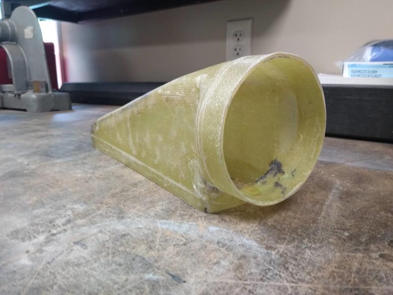
I needed a custom air duct to direct air from the side vents to the transmission cooler, so I decided to try my hand at making a custom mold for a wet fiberglass layup. I have never really done a complete fiberglass part, from mold to finished part. I marvel at the skill of some of the people here like aquillen who make entire manifolds in carbon fiber! But here is my simple part.
I mocked up what I needed in wood as the sizes were easy and I have lots of scrap laying about. I then used automotive body filler to fill the gaps and sanded it out to get a smooth finish. To make it easier to get the mold out I separated it into two sections so in theory I could just pop each piece out.
IMG_20200701_142955781.jpgIMG_20200701_143005051.jpgIMG_20200701_162053280.jpgIMG_20200701_163118575.jpg
After waxing the mold twice and then coating everything in PVA release agent I laid up a total of three layers. First layer was cloth followed by mat and a final layer of cloth. When it came time to pull the mold out it would not come out, even after unscrewing the two separate sections. I ended up destroying the mold by digging out the wood layer by layer. I drilled many large holes with a large forstner bit to hog out as much wood as I could before going at it with a wood chisel. Eventually I got it all out and the part was actually a great fit.
IMG_20200704_112410174.jpgIMG_20200704_093801578.jpgIMG_20200704_140920519.jpg
Once I get it mounted to the cooler and the air piped to it from the side vent I'll post more pics.
-
07-04-2020, 06:23 PM
#711
Thinker of thoughts

You probably know that you can use styrofoam for something like that instead of wood. Cover it with packing tape so the resin wont dissolve it. When done, dissolve out the foam and pull off the tape. Ive done a lot of small fibreglass pieces like that. I use the pink foam as it doesn't get beads everywhere as bad as the white stuff. But what you made looks very nice!
-
Post Thanks / Like - 1 Thanks, 0 Likes
-
07-04-2020, 06:56 PM
#712
Hobby, I had the same problem and have since found that wrapping the mold in Saran Wrap works very well for separating the part from your mold.
-
Post Thanks / Like - 1 Thanks, 0 Likes
-
07-05-2020, 12:25 PM
#713
Senior Member
Originally Posted by
FFRWRX
You probably know that you can use styrofoam for something like that instead of wood. Cover it with packing tape so the resin wont dissolve it. When done, dissolve out the foam and pull off the tape. Ive done a lot of small fibreglass pieces like that. I use the pink foam as it doesn't get beads everywhere as bad as the white stuff. But what you made looks very nice!
Originally Posted by
lance corsi
Hobby, I had the same problem and have since found that wrapping the mold in Saran Wrap works very well for separating the part from your mold.
Great suggestions. I'm going to try these methods when I do the mating piece that bonds to the inside of the side vent, thanks!
-
07-05-2020, 12:54 PM
#714
Thinker of thoughts
Originally Posted by
Hobby Racer
Great suggestions. I'm going to try these methods when I do the mating piece that bonds to the inside of the side vent, thanks!
Do one or the other. I think the resin may go through the Saran Wrap and attack the foam. It won’t stick to packing tape, so you don’t need another release agent. I seem to recall a guy at a fibreglass supply place telling me that Saran Wrap was very similar to release agents (PVA maybe, but I don’t remember) so that is a good suggestion to try if you want to stick with a wood mold.
That is a very nice duct you are making. More pictures as you progress please.
-
07-05-2020, 01:33 PM
#715
Yes, I love Technology
When I wax, I use about 8 to 10 coats, not just a couple, PVA also needs to be well coated. A couple tricks to de-mold include warming it up so the glass can flex away from the mold surface, and figure out how to blast high pressure air down between the parts while pulling - sometimes that really works well. In your case you (could have) drilled through the center of the wood, or a tiny hole in the back of the new glass, and put HP air in that to pop the thing out. But you are there.... so happy now!
-
07-05-2020, 04:56 PM
#716
Senior Member
Originally Posted by
aquillen
... blast high pressure air down between the parts while pulling - sometimes that really works well. In your case you (could have) drilled through the center of the wood, or a tiny hole in the back of the new glass, and put HP air in that to pop the thing out. But you are there.... so happy now!
High pressure air piped through channels in the mold . . . that is a great idea . . . wish I had thought of it before, I could have saved the mold. ")
-
07-05-2020, 05:52 PM
#717
Senior Member

fiberglass resin doesn't stick to duct-tape. Which just reinforces my opinion that duct-tape is is magic. I've wrapped the plug with duct-tape to very good success, before I even tried using mold-release wax & PVA. Regardless, that is a very nice looking part!
818SC chassis #206 EJ207 2.0L VF37 twin scroll || Cusco type RS 1.5 LSD || Wilwood pedal box (firewall attach) || Wilwood superlite front calipers
BUILD Phase 1: 6/6/2014 car delivered || 5/24/2015 first start || 6/7/2015 go karted || 4/20/2016 hard-top-topped || 10/25/2016 registered || 11/18/2016 inspected & complete
BUILD Phase 2: 3/8/2017 EJ207v8 || 5/29/2017 re-first re-start || 7/17/2017 re-assembled with race car bits
-
07-05-2020, 06:14 PM
#718
Senior Member

This fabrication is insanely awesome! Too bad molds are a one time use. 
Frank
818 chassis #181 powered by a '93 VW VR6 Turbo GT3582R
Go-karted Aug 5, 2016 - Then May 19+21, 2017
Tracked May 27/July 26, 2017
Build time before being driveable on Sep 27, 2019: over 6000h
Build Completed Winter 2021
-
07-05-2020, 07:19 PM
#719
Senior Member

Originally Posted by
Frank818
This fabrication is insanely awesome! Too bad molds are a one time use.
...not always...
IMG_4690.JPG
Foreground Kevlar top...background cardboard mold
Jetfuel
-
07-06-2020, 03:14 PM
#720
Senior Member
Composite Trans Cooler Ducting Complete

I completed the transmission cooler ducting that grabs air from the driver's side vent and forces it through the transmission cooler. I trimmed the short ends of the fiberglass duct so that the long edges seal up against the cooler body forming a tight seal. The end caps are short and only need a small piece of foam to completely seal the edges. I made two small aluminum brackets to affix the duct to the cooler mount and then routed the hose.
IMG_20200706_103900245.jpg IMG_20200706_103910680.jpg IMG_20200706_141938580.jpg
I ended up using a 4" hose made for dust collection systems in a wood shop. I'm not sure about it's heat rating but it is not real close to anything hot, fingers crossed that it holds up. If it doesn't I'll have to use automotive silicone hose, but that's $$$.
Until I get a chance to take the body off again and mold a nice piece to fit the driver's vent, I made an aluminum arm that holds the hose end in place just inside the side vent. That should suffice for now.
IMG_20200706_152051248.jpg IMG_20200706_152032958.jpg IMG_20200706_152058941.jpg
All in all I'm happy with how it turned out. I'll do testing next week at my first track event this season. I'll report back on how it works.
Last edited by Hobby Racer; 07-06-2020 at 03:17 PM.
-
Post Thanks / Like - 0 Thanks, 2 Likes


 Thanks:
  Likes:


 Reply With Quote