-
Senior Member

Spent the last week tinkering and building my fuel lines. I posted separately a few questions I had but once I got the hang of what to do things went smoothly. Installed the fuel level sending unit, the fuel tank vent and temporarily fit the fuel pump hanger. I also received the first batch of my powder coating back. I dry fitted and cleco'ed everything in place as I finalize a few other details. I was surprised at how everything went back together quite well. Just a bit of bending, pressing and paying attention to the joints so I know what order to assemble things when caulking and riveting. Next steps will be to caulk and rivet the panels in place. I'm really glad I went with the matte black PC, I think it looks great. I'm just trying to decide if I go with the aluminum rivets as a contrasting color or buy black rivets that John suggests above.

-
Senior Member
I've been busy with life but got plenty of work done over the last few weeks. Completed my fuel lines and tested them successfully. Received a few more POL/MIK parts from FFR and finally received my certificate of origin and serial number plate.
As of this weekend I was able to caulk and rivet the PS footbox as well as most of the DS footbox (bottom, engine side and front). I'm leaving the top and side off the drivers side to allow access as needed in the future. Additionally I was able to complete the seat heater installation into my seats. I used the DAP Weldwood contact cement and it went well. Just make sure you allow it to sit for a while ~15 mins before you stick things together. I also stacked a few heavy boxes on them once complete to keep everything in place while I worked on other things.

Also finished caulking and riveting the firewall.

This is feeling more like a car again!
Next steps will be to finish the hard rear brake line (I went through the inside of the DS footbox, right behind the Coyote accelerator pedal mount), and mount the fuel lines. Once these are complete I'll close up the cockpit and trans-tunnel sides. Then on to wiring. Not something I'm looking forward to but I started laying things out and it appears pretty straight forward (famous last words!).
I find myself getting caught up in one task then forgetting what other task I actually started. Building my own spreadsheet with as many tasks as I can find, and working to keep myself on track!
Last edited by Junbug; 04-09-2023 at 11:12 PM.
-
Senior Member
-
Post Thanks / Like - 0 Thanks, 2 Likes
-
Senior Member

Hi Bryan. Welcome to powder coating. It's so handy to be able to do the small pieces in your own garage. Looking good.
Yes, those 3/4" brackets need to be removed for the Breeze upper radiator mount.
Chris
Coupe complete kit delivered: 4/22/24.
Build Thread. Coyote. T-56. IRS w/3.55. Wilwoods. PS. HVAC. Side windows.
MK4 Complete kit.
Build Thread Index. Delivered: 10/15/2020. Legal: 7/25/23. Coyote Gen3. TKO600 (0.64 OD). IRS w/3.55. PS. Wilwoods. Sway bars. This build is dedicated to my son, Benjamin.
Build Thread.
-
Post Thanks / Like - 1 Thanks, 0 Likes
-
Senior Member
-
Senior Member

Great job on the PC! It’s really rewarding. I needed up PC all kinds of stuff that didn’t need it just because it was fun. Like tools and thing laying around the house.
I really like the black panels with the silver rivets. The contrast looks great.
MK4 #10008 - Ordered 10/06/20, Delivered 03/03/21, First Start 7/22/21, First Go Kart 7/24/21
Paint by Metal Morphous 5/14/22, Legally registered 6/8/22, Graduated 7/20/22
Build Thread
https://thefactoryfiveforum.com/show...been-delivered
Complete Kit, Ford 306, Sniper/Dual Sync, T5, Hydraulic clutch
-
Post Thanks / Like - 1 Thanks, 1 Likes
-
Senior Member
Got caught up on a lot of small things this week and made some good progress. Started with finalizing the routing for my rear hard brake lines through the DS footbox. Similar route others have taken in the past, no need for more grainy pictures. I did add grommets to each of the 1/2" holes I drilled to both center the brake line as well as keep it away from rubbing the steel and aluminum edges. In addition to finishing the routing, I started riveting in the cushioned mounts to keep the brake line in place. Once i finished that, i started to connect all the brake fittings. Starting at the master cylinders and working to the wheels, I replaced the cleco's holding my cushioned clamps in place with rivets. Once at the wheels I connected the stainless steel flex lines to the wilwood hard/soft adapters and snugged everything up. As others recommended i put just a dab of brake fluid at each of the joints to help the flares seat together. If something looks off, please point it out (aside from my rear springs that have the FFR writing upside down). BTW I didn't connect both the front DS and PS side brake lines as others have mentioned the way I have them bent may interfere when I drop the engine in. So bleeding the brakes may be a bit of a wait.

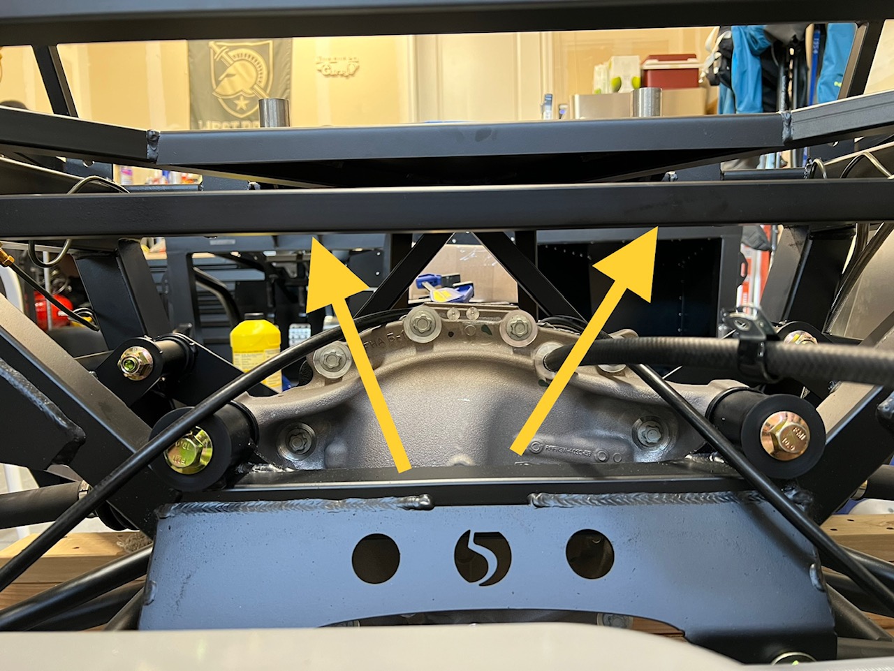
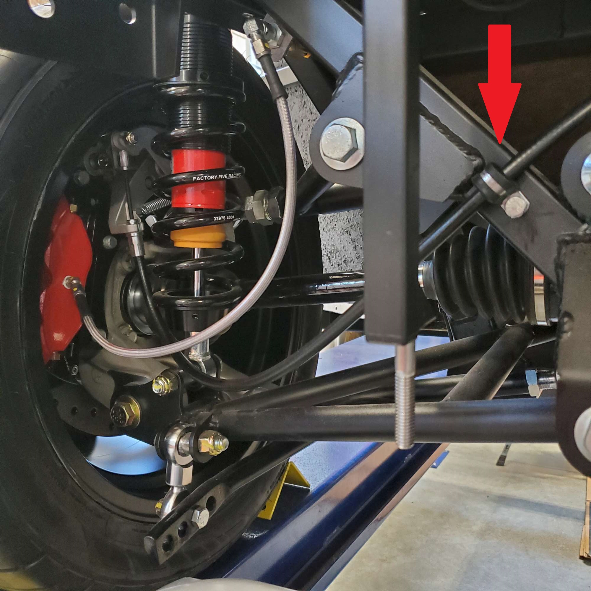
Next I installed the emergency/parking brake lines. That was pretty straightforward and I got to mount a few of the pieces I powder coated last weekend. As far as the routing of the e-brake cables, are the good to just lay where they are, or do some lift them up and hold them off the rear diff with cushioned clamps? Maybe where I have the yellow arrows pointing? Just a thought but I haven't seen other options...
Now that I've installed both my fuel lines and my rear brake lines, I decided I could complete the cockpit aluminum. I installed both the passenger side as well as the drivers side. Installation was pretty straightforward. I dry fit a few times, made a few minor adjustments then put down my clear silicone, dropped in the aluminum and then cleco'ed in a a few places as I riveted everything in place. I plan to do something others have done with the top of the transmission tunnel, but I haven't' decided yet...

-
Senior Member

Originally Posted by
Junbug

As far as the routing of the e-brake cables, are the good to just lay where they are, or do some lift them up and hold them off the rear diff with cushioned clamps? Maybe where I have the yellow arrows pointing? Just a thought but I haven't seen other options...
Hi Bryan,
I didn't want the e-brake cables loose, so I secured them close to the area you noted above, but down a bit on the diagonal.
Chris
Coupe complete kit delivered: 4/22/24.
Build Thread. Coyote. T-56. IRS w/3.55. Wilwoods. PS. HVAC. Side windows.
MK4 Complete kit.
Build Thread Index. Delivered: 10/15/2020. Legal: 7/25/23. Coyote Gen3. TKO600 (0.64 OD). IRS w/3.55. PS. Wilwoods. Sway bars. This build is dedicated to my son, Benjamin.
Build Thread.
-
Senior Member
Thanks Chris! I appreciate the feedback and the picture. I didn’t like how they just flop around. A few nice cushioned clamps like you used will be helpful. Thanks again
-Bryan
-
Post Thanks / Like - 0 Thanks, 1 Likes
-
Senior Member
So its been a few weeks of work and family travel but I've been making slow and steady progress on my punch list of minor things that needed to be addressed. The first thing was that the coyote accelerator pedal was touching the side of the cockpit aluminum. I pulled the pedal off and as recommended on a few other threads made a small channel and did a bit of sanding that moved the top right hand side of the accelerator pedal away from the cockpit wall by about 1/2".

Next was designing and cutting out all the holes for my gauges. This took the better part of an afternoon, but templates, blue painters tape and a dremmel with a cutoff wheel and a sanding drum made things pretty easy. I just went slow, with plenty of protective gear (respirator, eye protection and long sleeves/pants). I prefer this layout, and regardless of whether i like it in the long run or not, its what I've got!

I also finished powder coating a bunch of other small parts, and was able to mount the hydraulic reservoirs for my brakes. The tops of the reservoirs sit about level with the 3/4" bar, so they should clear the hood no problem.

I also modified the bracket that came with my aeromotive fuel pressure regulator. The bracket is a 90 degree bend and bolts to the bottom of the regulator. I took it off and gently used a hammer and bent the piece flat. Once mounted to the bottom side of the 2"x2" at the base of the upper firewall, it stands off the firewall and leaves a 1.5" gap that allows the coyote engine wiring harness to run over to the PS footbox and on into the PS engine compartment. Many variations of the similar modifications out there. The fuel lines are just hooked up so I know how much slack I have. I won't hook them up completely until the engine is in.

Lastly I realized that FF sent me the accessories for a hydraulic clutch, where I am using a cable. Thus the part to actuate the coyote clutch safety switch wouldn't work, as delivered. I ended up taking what they sent and modifying it to fit my needs. Just a bit of trimming and sanding (wish I had a bench grinder) and I think I solved the problem. Plenty of adjusting still needed on the clutch safety switch's final location but its adjustable and I won't touch it again until the engine and clutch cable is installed. Based on others recommendations I plan to get a genuine Ford clutch cable. I understand its a "must do" for both ease of use and reliability.

Next big steps are wrapping up everything in the trunk area so I can install the drop trunk, trunk aluminum and then the rear cockpit wall. Once done with that, I'll be moving on to lots of prep work to spray the Lizardskin heat and sound insulation. I plan to spray both in the cockpit and only the sound insulation in the interior trunk area.
-
Post Thanks / Like - 0 Thanks, 1 Likes
-
Senior Member
-
Post Thanks / Like - 0 Thanks, 1 Likes
-
Senior Member
-
Senior Member
-
Post Thanks / Like - 0 Thanks, 1 Likes
-
Senior Member
Thanks for the cool pictures from your BMW/Porsche tour, Bryan. Looked like a great time.
I bet you'll be happy with your LS choice. Looks like a quality product. Congrats on being almost done with it...lots of work in the prep and application.
Chris
Coupe complete kit delivered: 4/22/24.
Build Thread. Coyote. T-56. IRS w/3.55. Wilwoods. PS. HVAC. Side windows.
MK4 Complete kit.
Build Thread Index. Delivered: 10/15/2020. Legal: 7/25/23. Coyote Gen3. TKO600 (0.64 OD). IRS w/3.55. PS. Wilwoods. Sway bars. This build is dedicated to my son, Benjamin.
Build Thread.
-
Post Thanks / Like - 1 Thanks, 1 Likes
-
Thanks for the photos from the BMW/Porsche/Mercedes museums. That's pretty cool that you were able to visit them! Definitely on my bucket list.
Nice work on the LS. It turned out great. It's a lot of work to prep and spray but I agree with Chris, you'll be happy with the final outcome. It's a good product.
MkIV Roadster build: Gen 2 Coyote, IRS, TKO600. Ordered 10/24/18. Delivered 1/29/19. Engine installed 8/8/21. First start 9/12/21. First go-kart 9/17/21. Off to paint 4/11/22. Back from paint 12/30/22.
Build thread here.
-
Post Thanks / Like - 1 Thanks, 1 Likes
-
Senior Member
Spent the last few weeks working on laying out the wiring/power system as well as catching up on small details here and there. Below is a pic of the latest progress.
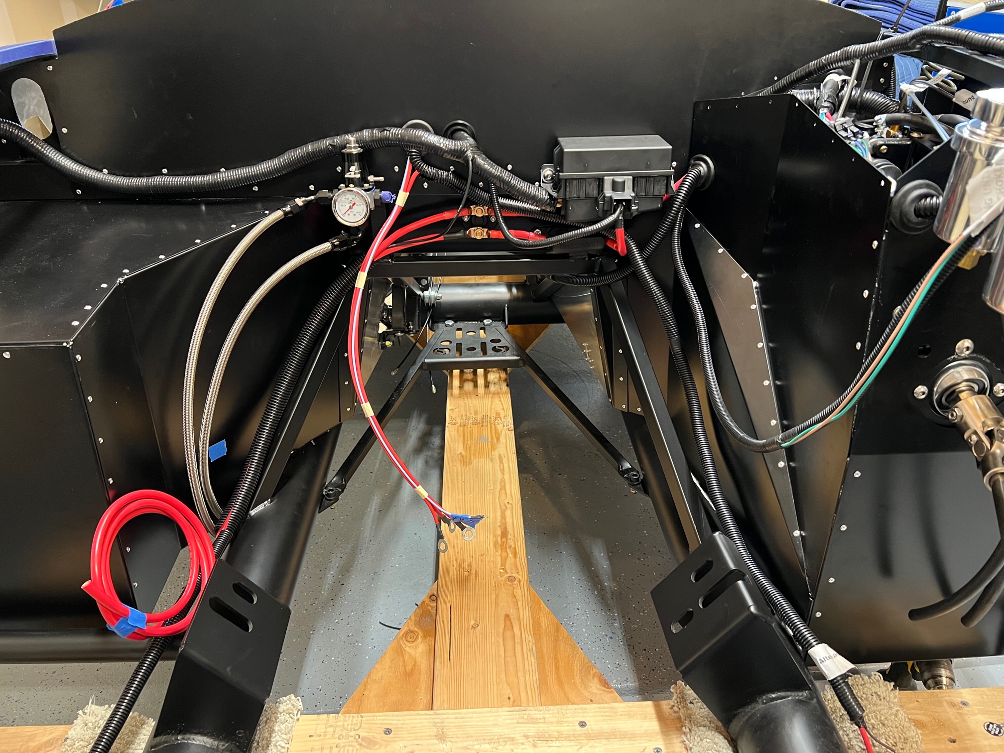
Battery/power wiring is 90% done, cuttoff and PDB fuse is in with 4 gauge connections. All the FFR and Coyote harnesses are installed, excluding the engine harness as that is connected to the engine. Going from left to right across the dash: Alternator and Starter harness (part of the main harness behind the dash), Coyote harness (the line running left goes to the main Coyote computer, below that you can see the power cutoff switch (wired like EdwardB and JohnK), next to the cutoff is the main PDB fuse, above that is the Coyote fuse box (PDB), to the right of that is the rear harness, sending unit harness and the 4 gauge lead that will go to my power bus bar in the cockpit.
The other side of the dash looks like this.

Lots still to do! I have the rear harness hooked up, the sending unit installed as is (may add the Coyote provided oil pressures and water temp wires to that harness).
You can see the 4 gauge lead just hanging out until I get my power bus bar installed.
I'm still working on final locations for the Headlight switch, ignition (key) and the inertia switch.
I have a self imposed deadline to get my engine in before my son heads off to school at the end of this month. Next few steps are focused on prepping to accomplish that goal.
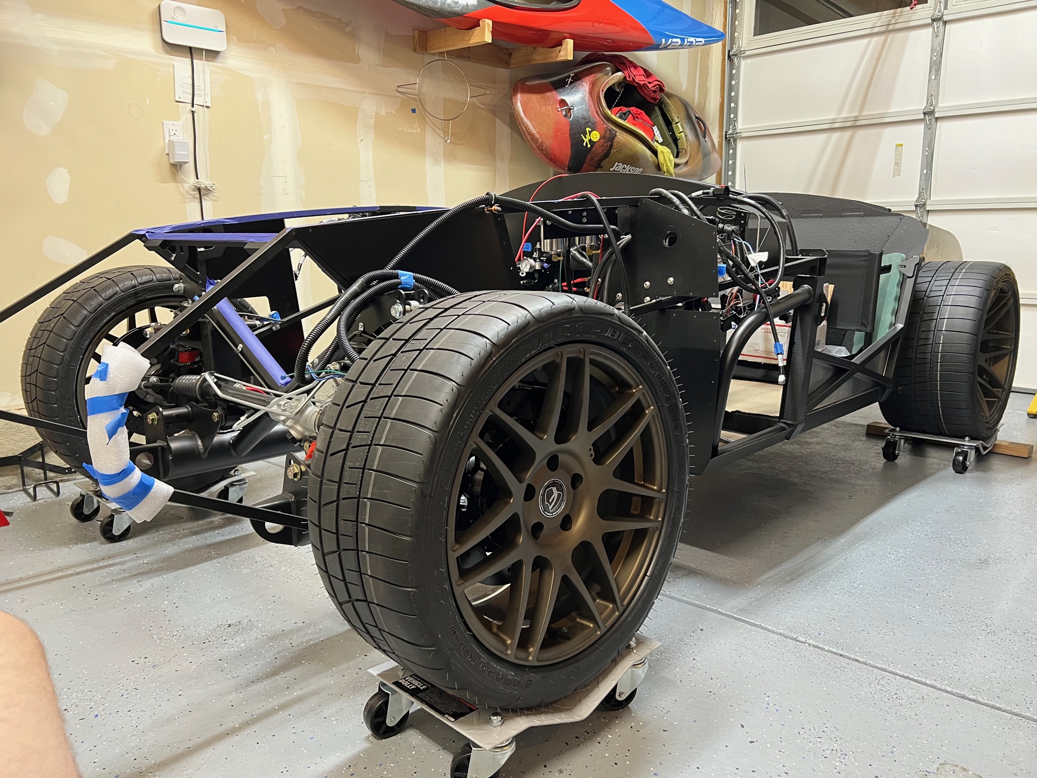
1. Get tires installed on wheels, and get them on the car so the car can be mobile (ie. off the dolly)
2. Get wiring completed enough to install engine
3. Install PS system on engine
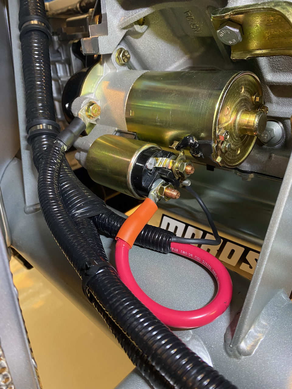
4. Install starter on engine
5. Install oil temp and water temp senders on engine
I'm hoping those will be all I need to do before dropping the engine in. Then I'll have about 9 weeks before my son is back to continue electrical, install the cooling system, bleed and test the brake system, and hopefully fuel up (only a few gallons) for a first start before the end of October!
-
Senior Member
-
Senior Member
Originally Posted by
Junbug
We also learned that with Mike Forte's engine stand, there isn't room to install the starter. We added it to the very short list of things to do once the engine is in the air... or once its installed... Any tips/advice would be appreciated. You can see where the legs of the engine stand interfere with where the starter needs to be.
Additionally in the photo above you can see Mike Forte's engine lift brackets. As many have pointed out, they are fine for moving the engine around but will interfere with installing the headers while you're installing the engine. So we ordered coyote engine lift brackets from TD Motion. Below is a pic of them installed with arrows pointing to them.
Things are coming together, Bryan. Looking good.
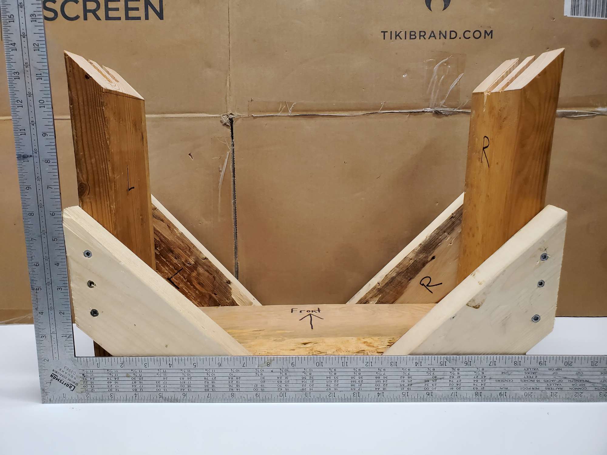
I had the same issue with getting the starter installed with Forte's "engine stand". Inspired by Edwardb, I made this in lieu of an engine stand (I don't have one), so I could install the starter, etc. And, X2 on replacing Forte's engine lift brackets.
Chris
Coupe complete kit delivered: 4/22/24.
Build Thread. Coyote. T-56. IRS w/3.55. Wilwoods. PS. HVAC. Side windows.
MK4 Complete kit.
Build Thread Index. Delivered: 10/15/2020. Legal: 7/25/23. Coyote Gen3. TKO600 (0.64 OD). IRS w/3.55. PS. Wilwoods. Sway bars. This build is dedicated to my son, Benjamin.
Build Thread.
-
Post Thanks / Like - 1 Thanks, 0 Likes
-
Hey Bryan. Nice progress! JFYI - there's plenty of room to install the starter once the engine is installed. The passenger side of the engine has a plenty of space. It's only the drivers side that's super-cramped.
MkIV Roadster build: Gen 2 Coyote, IRS, TKO600. Ordered 10/24/18. Delivered 1/29/19. Engine installed 8/8/21. First start 9/12/21. First go-kart 9/17/21. Off to paint 4/11/22. Back from paint 12/30/22.
Build thread here.
-
Post Thanks / Like - 1 Thanks, 1 Likes
-
Senior Member
And today we mounted the wheels and got her on the ground, well on to wheel dollies so we can move her around!
-
Senior Member
Today was engine install day! Everything went relatively smooth and installing the coyote was pretty much as expected. A local Colorado builder lent me a 2T lift and engine leveler. (danmas). And Papa offered his as well, though Dan was a bit closer.
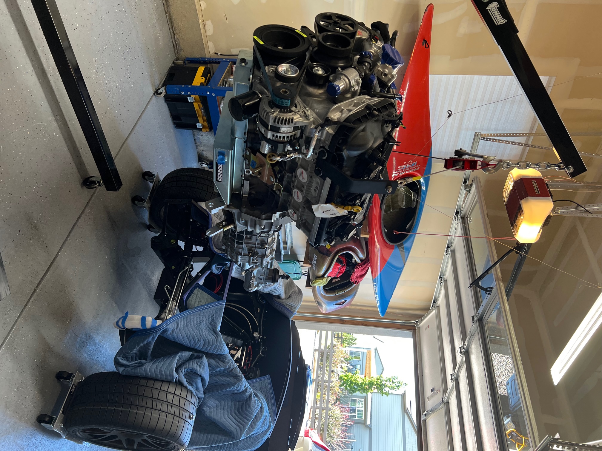
The overall process was pretty straight forward. One key, as shared by mmklaxer, make sure your engine (coyote) is level. Whether you're using chains, an engine leveler, or rubber bands... make sure its level (horizontally from side to side). This becomes key as you're lowering the engine into its final position. If you start tilted to the DS or PS side, it will make it very difficult to get the engine to drop into its final position evenly. Thanks to all others that shared tips, the entire engine install process took my 17 year old son and I about 2.5 hours, including bolting on the headers. The headers themselves took us around 1.5 hrs. We took our time as this was our first time putting any engine in.


Installing the headers wasn't fun, but it wasn't impossible either. We have the FFR coyote headers and I purchased socket head screws based on the advice of others and it went relatively smoothly. Like I said above, it took us about 1.5 hrs to get the gasket and all header bolts installed and torqued. When I say torqued, about 4-5 per side are accessible with a torque wrench/extension combo. The others were torqued via my "calibrated" right arm.
There are likely more details to share, but it went much smoother than I thought, being my first time. Of course our pup needed to get into the pics as she likes to be around us when we're wrenching in the garage, and I stuck a few of Mike Forte's head stickers on her for show...

-
Post Thanks / Like - 0 Thanks, 1 Likes
-
Senior Member
Just for fun I took a few pics of the "clearance" on the DS and PS of the engine bay with the coyote installed. As you can see below, the passenger side has a massive 1" of space between the top of the head and the PS footbox. It does get wider as you go down the head/footbox.

And here you can see the gap on the DS. This pic is looking from front to back at the gap between the head and the DS footbox. My ruler is pressed against the front of the DS footbox.

-
Post Thanks / Like - 0 Thanks, 1 Likes
-
Senior Member
Congrats, Bryan. Great work! As you experienced first hand, it is a tight fit indeed. This first timer looked in disbelief beforehand thinking there's no way it's going to fit. Then looked in disbelief afterward and amazed at the shoehorn fit.
How many young men your son's age can say they installed a motor? Not your average Saturday afternoon. I'm excited for you guys. Thanks for sharing the pics.
Chris
Coupe complete kit delivered: 4/22/24.
Build Thread. Coyote. T-56. IRS w/3.55. Wilwoods. PS. HVAC. Side windows.
MK4 Complete kit.
Build Thread Index. Delivered: 10/15/2020. Legal: 7/25/23. Coyote Gen3. TKO600 (0.64 OD). IRS w/3.55. PS. Wilwoods. Sway bars. This build is dedicated to my son, Benjamin.
Build Thread.
-
Post Thanks / Like - 2 Thanks, 0 Likes
-
Senior Member
-
Senior Member
-
Senior Member
-
Post Thanks / Like - 0 Thanks, 1 Likes
-
Senior Member
So I had a busy few weeks but I've been able to dedicate a good 1/2 day every weekend to the car. Still have a goal of the first start in mid-October.
For starters, I learned that I don't need this speed sensor connector coming off the rear harness. As I have the Vintage gauges and they're fed by the GPS antenna, I cut the wires, taped them off, put shrink wrap on them and tucked them back into the loom.

I also made some solid progress on the cooling system. In my last post you can see the coolant expansion tank, the two brackets I created and then installed. Next I installed the Breeze upper, lower radiator mounts and the radiator shroud. All pretty straight forward though with many temp installs and adjustments to make sure all the brackets fit well and I could maintain the 51 degree radiator angle. Its starting to look like a car! Or at least has all the pieces visible that together make a car!

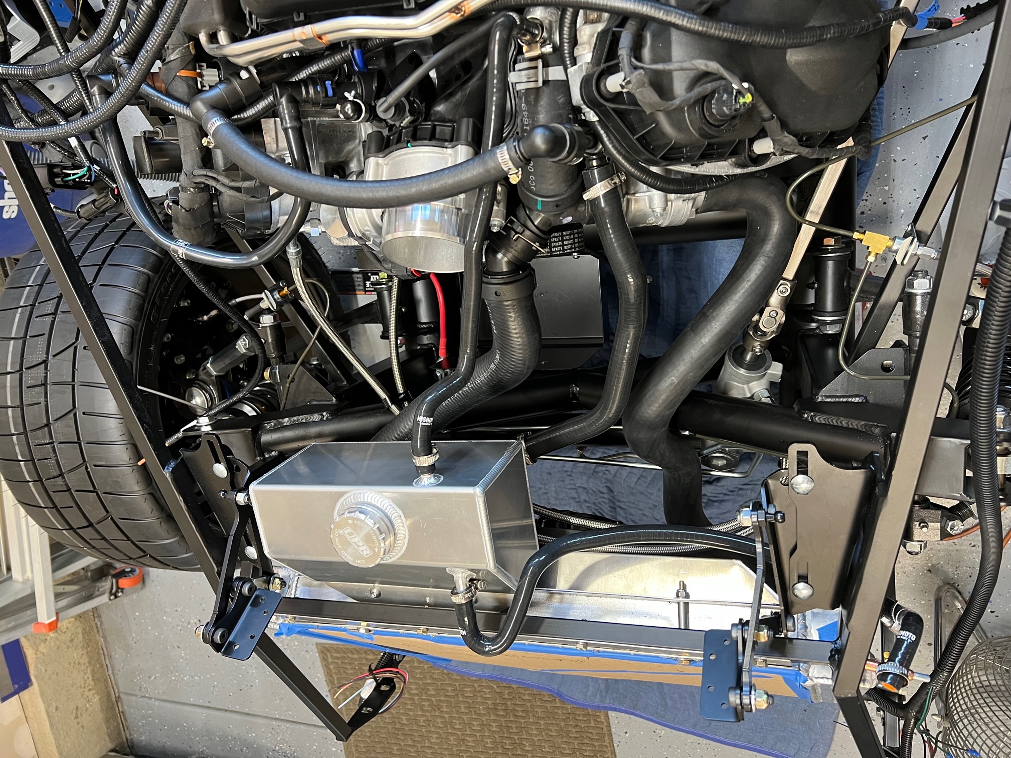
Here are a few more detailed photos of the radiator and expansion tank hose connections. I ended up buying the Mishimoto silicone ancillary coolant hose kit. Everything fit perfectly on the expansion tank and to both the engine and the radiator. Kit comes with three hoses: one to connect the bottom of the expansion tank to the engine, one connecting the steam overflow from the engine to the top of the expansion tank, and one connecting the top right (DS) of the radiator to the expansion tank (including the built in reducer). All hoses come with hose clamps as well. Great kit.

For the lower radiator hose, I used the kit provided hose and cut about 1" off the top where it connects to the lower coolant output on the engine. I trimmed just enough to make sure it cleared the steering shaft and my brake line. I searched a lot of threads and asked fellow builders about the best routing for this lower hose, and through trial and error, I ended up finding it fit best, with fewest kinks or twisting of the hose, running it over the X-brace and down the front of the PS rack.


I plan to purchase the Gates power grip hose clamps for the two large hoses, the others I'll use the Mishimoto provided hose clamps. Those should all go on in the next week or so.
For the top hose, I purchased a Motorcraft (KM5114) hose from Amazon. I understand this hose is for a ford F-150, but works perfect for this application. The end connecting to the coyote has a Ford designed wire snap connector designed to mate to the Coyote. One adjustment many others have also made is to cut another small notch in the outer ring, allowing you to rotate the hose and hard plastic upper joint about 15-20 degrees away from the PS belt. Very simple to do and the hose locks in place perfectly. Disregard my PS pressure lines... they're in place but I"m still fabricating a bracket to hold them in place away from the fan shroud and the radiator hoses.

Below is a top down pic of all the hoses connected, but no clamps tightened.
-
Senior Member
-
Nice work. Couple of suggestions, that lower rad hose connected to the engine will swell when you run it and it gets hot and be up against that steering shaft, might have to trim off more where it connects to the engine. Not sure why all the washers on bellhousing bolts, you may want to get correct length bolts to install. Turn that MAF adapter tube so the sensor faces the front of the car. Just a couple things I have run into on my build.
Mk4 9735 complete kit delivered 11/29/19 Gen 3 Coyote, Tremec TKO 600, Moser 3.55 First start June 25, 2020 First Go Cart July 20, 2020
-
Senior Member
Originally Posted by
Jryasko
Nice work. Couple of suggestions, that lower rad hose connected to the engine will swell when you run it and it gets hot and be up against that steering shaft, might have to trim off more where it connects to the engine. Not sure why all the washers on bellhousing bolts, you may want to get correct length bolts to install. Turn that MAF adapter tube so the sensor faces the front of the car. Just a couple things I have run into on my build.
Thanks for the tips! The bellhousing bolts came like that from Mike Forte. I trust he did it for a reason, and now its buried inside the car... I"ll leave it for now. I'll take a bit more off the lower radiator hose... it clears the steering shaft by a finger but I'll trust your experience regarding the swelling. The MAF adapter tube should be facing the right directions, per the build manual and others... I've often been confused as to what way the sensor should face.
Thanks!
-
Originally Posted by
Junbug
The MAF adapter tube should be facing the right directions, per the build manual and others... I've often been confused as to what way the sensor should face.
Thanks!
One reason that MAF orientation can be confusing is because it is different for the Gen 2 vs Gen 3 coyote. For the Gen 2 engine the MAF should be pointed away from the engine whereas on the Gen3 it should be pointed toward the engine like you have it.
MkIV Roadster build: Gen 2 Coyote, IRS, TKO600. Ordered 10/24/18. Delivered 1/29/19. Engine installed 8/8/21. First start 9/12/21. First go-kart 9/17/21. Off to paint 4/11/22. Back from paint 12/30/22.
Build thread here.
-
Senior Member

Originally Posted by
JohnK
One reason that MAF orientation can be confusing is because it is different for the Gen 2 vs Gen 3 coyote. For the Gen 2 engine the MAF should be pointed away from the engine whereas on the Gen3 it should be pointed toward the engine like you have it.
Sure about that? I've done both Gen 2 and Gen 3 Coyote builds and in my experience they're both the same. In both cases (no reason for them to be different) the sensor responds to the amount of air flowing through the intake tube and into the throttle body. The open end of the sensor (the part that is in the airflow) must be pointed toward the air cleaner. The engine will typically start but almost immediately shut back off if the MAF is backwards and the PCM doesn't get the proper MAF signal.
Build 1: Mk3 Roadster #5125. Sold 11/08/2014.
Build 2: Mk4 Roadster #7750. Sold 04/10/2017.
Build Thread
Build 3: Mk4 Roadster 20th Anniversary #8674. Sold 09/07/2020.
Build Thread and
Video.
Build 4: Gen 3 Type 65 Coupe #59. Gen 3 Coyote. Legal 03/04/2020.
Build Thread and
Video
Build 5: 35 Hot Rod Truck #138. LS3 and 4L65E auto. Rcvd 01/05/2021. Legal 04/20/2023.
Build Thread. Sold 11/9/2023.
-


I'm only as sure as the FFR instructions, which to say, not very sure.  However, the FFR Gen 2 coyote install instructions state on page 56:
"Adjust the Mass air meter so that the mass air plug is on the far side as the Ford Performance instructions recommend."
Whereas the FFR Gen 3 coyote install instructions state on page 71:
"Adjust the Mass air meter so that the mass air plug is on the side close to the engine as the Ford Performance instructions recommend."
All that said, I agree with you that the important thing is for the opening of the MAF to be pointed toward the air cleaner. I'm not sure why or if clocking of the MAF relative to the engine makes any difference at all, but I figured someone went to the trouble to write this so probably better to follow it. The fact that it's different between Gen 2 to Gen 3 does make it all seem a bit more suspect, but back to Bryan's point it does also add quite a bit of confusion on the proper way to install it.
MkIV Roadster build: Gen 2 Coyote, IRS, TKO600. Ordered 10/24/18. Delivered 1/29/19. Engine installed 8/8/21. First start 9/12/21. First go-kart 9/17/21. Off to paint 4/11/22. Back from paint 12/30/22.
Build thread here.
-
Senior Member
Originally Posted by
JohnK
I'm only as sure as the FFR instructions, which to say, not
very sure.
However, the FFR Gen 2 coyote install instructions state on
page 56:
"Adjust the Mass air meter so that the mass air plug is on the far side as the Ford Performance instructions recommend."
Whereas the FFR Gen 3 coyote install instructions state on
page 71:
"Adjust the Mass air meter so that the mass air plug is on the side close to the engine as the Ford Performance instructions recommend."
All that said, I agree with you that the important thing is for the opening of the MAF to be pointed toward the air cleaner. I'm not sure why or if clocking of the MAF relative to the engine makes any difference at all, but I figured someone went to the trouble to write this so probably better to follow it. The fact that it's different between Gen 2 to Gen 3 does make it all seem a bit more suspect, but back to Bryan's point it does also add quite a bit of confusion on the proper way to install it.
I think what those instructions are referring to is it's generally considered best practice to have the MAF sensor on the outside curve of the air tube going into the throttle body. Not the actual direction of the MAF sensor in the MAF tube. It will only work one way as previously described.
Build 1: Mk3 Roadster #5125. Sold 11/08/2014.
Build 2: Mk4 Roadster #7750. Sold 04/10/2017.
Build Thread
Build 3: Mk4 Roadster 20th Anniversary #8674. Sold 09/07/2020.
Build Thread and
Video.
Build 4: Gen 3 Type 65 Coupe #59. Gen 3 Coyote. Legal 03/04/2020.
Build Thread and
Video
Build 5: 35 Hot Rod Truck #138. LS3 and 4L65E auto. Rcvd 01/05/2021. Legal 04/20/2023.
Build Thread. Sold 11/9/2023.
-
Senior Member
I also discovered this connector on the Tremec TKX isn't needed/necessary. Not sure what its intended for, but others have recommended to just leave it along for the ride...
I believe that is your reverse switch. If you are using backup lights you would run it through that switch so the lights turned on when the transmission was in reverse. I have a T5 and mine is a little different but its the same 2 pin round connector.
MK4 #10008 - Ordered 10/06/20, Delivered 03/03/21, First Start 7/22/21, First Go Kart 7/24/21
Paint by Metal Morphous 5/14/22, Legally registered 6/8/22, Graduated 7/20/22
Build Thread
https://thefactoryfiveforum.com/show...been-delivered
Complete Kit, Ford 306, Sniper/Dual Sync, T5, Hydraulic clutch
-
Post Thanks / Like - 1 Thanks, 1 Likes
-
Senior Member
Originally Posted by
edwardb
I think what those instructions are referring to is it's generally considered best practice to have the MAF sensor on the outside curve of the air tube going into the throttle body. Not the actual direction of the MAF sensor in the MAF tube. It will only work one way as previously described.
Paul, John,
I appreciate the discussion and confirms that there is not clarity in the instructions. Both of your inputs are helpful and hopefully help future builders. Mine is installed with the sensor facing the air intake, pointing away from the engine...
-Bryan
-
Senior Member
-
Senior Member
Next big steps are fluids. Fill the engine with oil, radiator with coolant, power steering fluid, transmission fluid, and brake fluid. Also install a battery! Then once my son is back from school for a few weeks we'll test all the systems, bleed the brakes and go for our first start!
I have a growing list of things to do after first start and before go-cart but focus now is getting things ready for first start!
Last edited by Junbug; 10-03-2023 at 06:46 PM.
-
Post Thanks / Like - 0 Thanks, 1 Likes
-
Senior Member
-
Senior Member


 Thanks:
  Likes:


 Reply With Quote


