-
Senior Member


Originally Posted by
460.465USMC

Oh, boy. I wonder how many of these I've had on this project? I think I've decided I don't have any ten minute jobs.

Keep up the good work and enjoy.
Thanks, Chris. I think maybe we share some of the same perspectives on this project!
-
Senior Member
Oops!
I have an embarrassing confession: I did a neat job of installing my drop trunk, except that I installed it backwards. Standing behind the chassis, looking forward while reviewing the instructions, I got my thinking backwards and started to view the part farthest from me as the rear, whereas it was actually the front (I didnt misunderstand the instructionsI just wasnt thinking correctly).
As a result, my drop trunk is an inch further back than its designed to be. This location is solid and functional, but it required an ugly mod because the back lip of the drop trunk had to go over top of the ¾ tube in the rear of the chassis. This meant that instead of lifting the piece straight up into place, I had to lift it up, and slide it back over the ¾ tube. This in turn meant that the slots I cut to clear the frame diagonals had to be enlarged by an inch to enable the slidingits not what most people would consider fine craftsmanship. Its all going to get patched, siliconed and covered with carpet, but I still hate that I did that.
At the start of my thread, I said that my contributions to this forum would probably be in the form of what NOT to do, so I guess Im being true to my word. I just hope that Im not too prolific with that sort of advice.
Last edited by buttsjim; 11-15-2022 at 01:02 PM.
Reason: Added Title
-
Senior Member
Front Brake Lines
I wasted almost an entire 3 day weekend doing household chores and yard work, so only spent about 4 hours on the Cobra (my opinion, not shared by my wife, is that a perfect 3 day weekend is 36 hours spent on the Cobra, but nothing else about this project has been perfect, either). My 4 Cobra hours were spent on finalizing my front brake system. Other than household plumbing, Ive never done any tube bending and routing, so I had no idea how it would turn out.
I used some vinyl-clad clothesline wire to make a template so that my lengths and bends would be close. That product worked fairly wellit held the bends with no problem, but it would also twist, so that it didnt do well with compound angles.


In addition to the more common type of tubing bender, I used the Eastwood plier type bender for some of my touchup bending. That tool works very well, except that it tends to scar the tubing finish. I used some electrical tape to cushion it and that helped somewhat.

I ran the wheel-to-wheel brake line along the front X-member, just like Ive seen everyone else do, and Im happy with that result.


I ran the line from the front tee to the master cylinder along the ¾ frame tube. I think that I put a bit more bend in that line than needed, but Im happy with it. There is no need to coil the line going into the MC, as there is no stress from chassis flex on this line. However, this was a design as you go effort, and when I got back to the MC, I decided that it would be easier to coil the line, rather than cut and re-flare it. The coil takes up some space, but theres still room for my back ordered clutch MC and line.


The clutch and rear brake lines, I plan to run to the right, and down the inner footbox wall, and then along the 4 tube. Id like to do this near the front of the footbox, but since I havent installed my throttle pedal, I dont know what kind of clearance I have in that area.
I wanted to have my IRS in place before plumbing my rear system, but Ive decided to go ahead with that task next, and route everything based on what others on this forum have done.
All my cushioned clips are on backorder, so I'm temporarily using masking tape to support the lines, if needed.
-
Senior Member

Originally Posted by
buttsjim
All my cushioned clips are on backorder, so I'm temporarily using masking tape to support the lines, if needed.
Instead of waiting for the cheap and ugly cushion clamps take a look at these. They work great and can barely be seen.
-
Senior Member
Originally Posted by
Mike.Bray
Instead of waiting for the cheap and ugly cushion clamps take a look at
these. They work great and can barely be seen.
I like those! I can get by with just one package of six, if I only use them in the places where they're visable. Thanks!
-
Jim, you are making great progress. Your brake lines look really good. As for your backwards drop trunk install, you now can call it a "custom" installation 
MK IV Build #9659, 3 link, 17's, Forte 347, Sniper EFI, power steering, built for a freak sized person with 17" Kirkey Vintage seats, RT drop trunk, RT turn signal, lots of stuff from Breeze Automotive, Wilwood brakes, paint by Jeff Miller
-
Senior Member
Originally Posted by
TMartinLVNV
As for your backwards drop trunk install, you now can call it a "custom" installation
Thanks Terry--I like the way you think!
-
Senior Member
IRS is in!
I was excited to finally receive all the fasteners for my IRS last week, and wasted no time in getting my rear suspension in place.
Since I'd already assembled all the components, I thought that I could bolt everything on the car in an hour or so. Not true. I already had the center section temporarily mounted, but it still took a bit of struggling and care to get all the bolts to line up, especially since theres the possibility of stripping the rear mounts in the center section. Then, once everything was finally in, I decided to put spacers in the front mounts to fill the quarter inch gap that I had there. Dan Golub at FFR said not to worry about that gap, but I just couldnt see where there was any flexibility in the chassis or the cast center section mounts to close it. So, I removed the bolts from the front mount, inserted two large washers in each and then re-bolted it.

The control arms also were a bit of a struggle to get them to fit in their mounts. Again, there were gaps (which are inevitable in a welded up chassis), that concerned me. Once again, Dan said no problem, press on, so this time I did. The pictures are typical of the gaps and bent mounting points. In the pictures, all bolts are torqued properly, and the steel portion of the bushing has solid contact, but I cant see how the rubber portion of the bushing can perform its function. However, I expect this is true for all the Mk IV chassis, so I sucked it up and pressed forward. I still lack my rear springs, but otherwise, the suspension is complete and this thing is finally starting to look like a car. Springs will only take a few minutes to install when they arrive.


Rear brake lines are next.
-
Hey, Jim. I just wanted to touch base. We are pretty-much neck-and-neck on our builds. I'm just failing repeatedly to keep up with my build thread. We have R&L foot box aluminum powder coated and installed (save for drivers outside wall), front suspension done, steering rack in with the steering shaft hanging like yours (need the d-tube still), all brake lines run, rear center section and upper arm in, but waiting on IRS fasteners to complete it. Hitting fuel system next. Fully prepped engine/trans sitting in the garage begging to be installed. Where r u located (just curious)? (NVM - just read that u are in San Antonio, and that you received your kit about 2 weeks before we did!).
Last edited by Alec; 11-28-2022 at 04:17 PM.
<><><><><><><><><><>
Mk4 Roadster complete kit Chassis F5R1010480RD
Ordered Dec 2021, Delivered Sept 2022, First start Mar 2023
Completed October 2023
IRS, Wilwood, 17" wheels, Forte 427W/TKX/EdelbrockEFI
-
Senior Member

Originally Posted by
buttsjim
Springs will only take a few minutes to install when they arrive.
There 'ya had to go and say it. 
Yeah, that IRS is very tight fit. Nice work getting it buttoned up. I'm enjoying following along.
Chris
Coupe complete kit delivered: 4/22/24.
Build Thread. Coyote. T-56. IRS w/3.55. Wilwoods. PS. HVAC. Side windows.
MK4 Complete kit.
Build Thread Index. Delivered: 10/15/2020. Legal: 7/25/23. Coyote Gen3. TKO600 (0.64 OD). IRS w/3.55. PS. Wilwoods. Sway bars. This build is dedicated to my son, Benjamin.
Build Thread.
-
Senior Member
Alec, thanks for reaching out. Sounds like you're a little bit ahead of me with your build. I'm waiting for both my D tube and steering wheel. I'll probably be starting on my fuel lines next.
-
Senior Member
[QUOTE=460.465USMC;509964]There 'ya had to go and say it.
I guess I kind of jinxed myself there.
It seems like I would eventually learn: whenever I do a job around the house or on the car, I always estimate how long it'll take, precise to the quarter hour. If I would just learn to multiply that estimate by four, I think I'd have a sportin' chance of being halfway close.
Thanks for your comments and encouragement--I've enjoyed your thread as well.
Jim B
Last edited by buttsjim; 11-29-2022 at 09:52 AM.
-
Senior Member
Rear Brake Lines
I completed the lines for my rear brakes last night, but I’m not entirely happy with the result. Wanting a continuous run with no unions, I bought a coil of 3/16” copper nickel. I chose the copper nickel thinking that the soft material would seal better at the fitting and be easier to work with. After buying it, I discovered that I actually prefer working with the steel lines provided by FFR-the CuNi bends too easily.
I straightened the coiled line with my homemade tubing straightener that I based on a YouTube video. The straightener fits in my vise, replacing its jaws, and it worked well. I already had the aluminum bar stock, so it just cost about $15 for the 8 little pulleys to make the tool.

I ran the line between the two rear calipers as shown in the pictures. I remembered Mark Reynolds’ recommendation somewhere in Yama Bro’s thread to mount the flex line brackets horizontally to keep the flex line working in a single plane. That advice made a lot of sense to me, so that’s the approach I took, and mounted the brackets on top of the ¾” cross member. I tried to locate everything with maintainability in mind, and I should be able to get to any of the connections without too much trouble. It’s hard to see in the pictures, but I have about an inch clearance between the top of each line’s curvature, and the trunk floor—plenty of room to remove the line if necessary. I used the clips suggested by Mike Bray earlier in this thread to secure the line to the chassis. These clips are neat, sturdy, and hold the line very securely, and I thank him for his suggestion.


Starting at the tee, I ran the copper nickel line down to the 4” tube and forward to the master cylinder. I originally planned on running the line on the inside of the footwell to the master cylinder but didn’t like the idea of drilling and sealing a hole in my cockpit floor. Instead, I ran the line diagonally up the front of the footbox and then back to the master cylinder. I put a small coil in the line to make it easy to connect to the master cylinder, just as I did for the front line. I haven’t secured any of this portion of the line yet because I don’t like it. The workmanship and functionality are fine but, considering the front and rear systems together, it seems cobbled together and unprofessional.
I had used the FFR provided lines for the front but switched to the copper for the back. Using different materials for similar parts of the same system makes it look like an emergency repair job accomplished with whatever materials were on hand, rather than a thoughtful and deliberate design. I’m also second-guessing myself about the little coils at the master cylinders, as they’re not very elegant. Nobody will see that when it’s all buttoned up, but I don’t like them. I also don’t like the look of the diagonal line in front of my footbox (for some reason, it seems like these lines should be horizontal and vertical, and run close to a protective chassis member). And finally, I can’t find any instructions for the clutch hydraulics, but all this is going to get even worse when that line is added. Ugh.
I’ll be re-doing a portion of the system to achieve a product that I’m happier with. If I remain content with the type of results I’ve just described, I’m not going to be very proud of my final product when the car is complete. There are several ways to fix this, I just haven’t decided which way yet.
This thread could eventually become quite popular in terms of providing examples of what NOT to do.
Last edited by buttsjim; 11-29-2022 at 02:41 PM.
-
Post Thanks / Like - 0 Thanks, 1 Likes
-
Senior Member
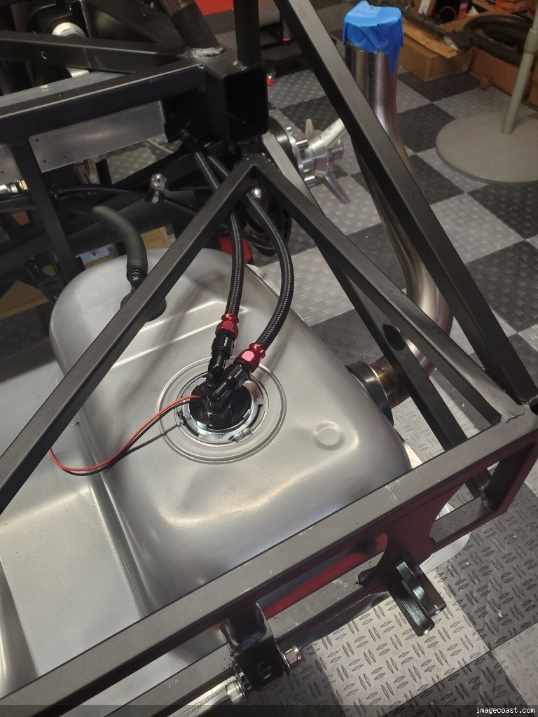
It’s been a long time since I’ve posted anything, and I haven’t done much, what with the holidays, a bout with covid, and a bunch of other activities. I finally got back to work this past week, starting with the fuel lines.
I decided on 3/8” copper-nickle alloy for the hard lines, black nylon rubber hose for the flexible portions, and compression AN fittings to put it all together. That combination should be good to at least 300 psi, plenty enough for fuel injection. However, don’t ask me why I chose compression fittings—I’ve never gotten along well with them, and I had the capability to make the 37 degree AN flares (I bought the Eastwood tool several years ago for his specific purpose, so ???). Rather than a permanently mounted pressure gauge, I added a Schrader valve to the supply line, and used the clips suggested by Mike Bray (earlier in this thread) to fasten it to the chassis.
I used a small in-line fuel filter from Summit and had planned on mounting it with the same type of roll bar clamp that Papa used on his. However, that size clamp wasn’t available, and I decided I didn’t need it anyway. Instead, I fit a piece of 1” square aluminum tubing into the unused chassis bracket over the rear wheel, fastened with 3/16” rivets, and used that as a mounting block for hose clamps on either side of the filter. The block provides a sturdy mounting for the filter and the lines, and the filter is easily assessable over the rear wheel.


I ran the hard lines to the engine bay just like everyone else. I’m not super happy with the way the lines look in the engine bay—they should be closer together and more parallel—so I may try and adjust them a bit. Later, maybe.


For those interested in gory details, I experienced quite a lot of self-inflicted frustration when fabricating the hard lines and ended up doing them twice. After bending and fitting the first set, I found that the compression fittings didn’t fit over the tubing because the tubing wasn’t perfectly round; the diameter varied from about .352” to .394” when measuring around the tube. I spent a good 30 minutes carefully sanding down the high spots and finally got the fitting to fit, but the completed fuel line wouldn’t hold pressure—not for one second. So, that proud effort was a big fail.
I didn’t realize it at the time, but I had flattened the tubing using my vise mounted tubing straightener, by slightly over tightening the vise to get the tubing as straight as possible. But, blaming the tubing, rather than myself, I ordered another 25’ roll, and was just starting to make the same mistake again, when I realized what I was doing. After a good slap to the forehead, I backed off on the straightening pressure, and ended up with a pretty good set of lines. I tested the new ones with about 90 psi, and didn’t have any bubbles when I submerged them, so I called it all good and installed them. I really like the look of the black nylon rubber flexible lines, and will use those to finish the system when the motor goes in.
Edit: the flexible lines are not rubber as stated, but steel reinforced nitrile, rated for ethanol.
Last edited by buttsjim; 03-17-2023 at 08:02 AM.
-
Senior Member
It might be one step forward, one step back at times. But, progress nonetheless. I, too, like the black lines. Nice option.
Chris
Coupe complete kit delivered: 4/22/24.
Build Thread. Coyote. T-56. IRS w/3.55. Wilwoods. PS. HVAC. Side windows.
MK4 Complete kit.
Build Thread Index. Delivered: 10/15/2020. Legal: 7/25/23. Coyote Gen3. TKO600 (0.64 OD). IRS w/3.55. PS. Wilwoods. Sway bars. This build is dedicated to my son, Benjamin.
Build Thread.
-
Senior Member

Looking good! One question for you are those black nylon braided hoses PTFE?
-
Senior Member
Originally Posted by
Fman
Looking good! One question for you are those black nylon braided hoses PTFE?
Thanks! Those lines are NOT PTFE--they're rubber. Plenty good for fuel injection, but not brakes or power steering. Besides liking their look, I thought that they'd be more flexible, and a tiny bit easier to work with. And cheaper. By the way, your thread has been very helpful to me.
Last edited by buttsjim; 01-19-2023 at 11:19 AM.
-
Senior Member
Originally Posted by
buttsjim
Thanks! Those lines are NOT PTFE--they're rubber. Plenty good for fuel injection, but not brakes or power steering. Besides liking their look, I thought that they'd be more flexible, and a tiny bit easier to work with. And cheaper. By the way, your thread has been very helpful to me.
If you're going to run pump gas you definitely want PTFE lined hoses.
-
Senior Member
Originally Posted by
Mike.Bray
If you're going to run pump gas you definitely want PTFE lined hoses.
I will be running pump gas, and the car will be driven regularly. I don't understand why I would need teflon, so could you explain? Now's the time for me to make the change, if that's what I need to do. Thanks for your input/advice!
Jim B
-
Senior Member
Originally Posted by
buttsjim
I will be running pump gas, and the car will be driven regularly. I don't understand why I would need teflon, so could you explain? Now's the time for me to make the change, if that's what I need to do. Thanks for your input/advice!
Jim B
Oh....ethanol, I bet. I think this hose is ok based on Summit's description (I used the term "rubber" too loosely--it's steel reinforced nitrile), but I'm checking with Summit to be sure.
Edit: Summit replied, it's rated for ethanol and methanol.
Last edited by buttsjim; 01-19-2023 at 02:33 PM.
-
Senior Member
Yep, it's almost impossible to buy pump gas without ethanol in it these days. Almost all hose manufacturers like Earl's are going to recommend PTFE lined for pump gas. I used Hot Rod Fuel Hose for my fuel lines and have been very happy with it. PTFE lined, good quality, and a fair price.
-
Senior Member
Originally Posted by
Mike.Bray
Yep, it's almost impossible to buy pump gas without ethanol in it these days. Almost all hose manufacturers like Earl's are going to recommend PTFE lined for pump gas. I used
Hot Rod Fuel Hose for my fuel lines and have been very happy with it. PTFE lined, good quality, and a fair price.
Yeah, I know that PTFE is best. That's what I had planned, but when it came time to order, I went a completely different route. I think the extra cost of the PTFE compatible fittings, the higher cost of the hose, and the better flexibility of the nylon/nitrite were the main reasons. By the way, your workmanship on your Cobra is outstanding, and I really appreciate having someone with your skills looking over my shoulder.
-
Senior Member
Originally Posted by
buttsjim
I think the extra cost of the PTFE compatible fittings, the higher cost of the hose
I never was one to cut corners when building cars, I always strived to "do it right" as my engineering mind told me to. Especially with these FFR cars that are basically street legal race cars with more power to weight than anything you've probably ever driven. In any build there are two areas I would never never even consider cutting corners, brakes and fuel. Brakes for obvious reasons. Fuel lines as a bad one can burn your car down and possibly you with it. Non-compatible hoses can start to deteriorate and clog your fuel filter, regulator, and injectors. It's just not the place to try and save a buck to me.
These are from Hot Rod Fuel Hose
-
Post Thanks / Like - 0 Thanks, 1 Likes
-
Senior Member
Originally Posted by
Mike.Bray
I never was one to cut corners when building cars, I always strived to "do it right" as my engineering mind told me to. Especially with these FFR cars that are basically street legal race cars with more power to weight than anything you've probably ever driven. In any build there are two areas I would never never even consider cutting corners, brakes and fuel. Brakes for obvious reasons. Fuel lines as a bad one can burn your car down and possibly you with it. Non-compatible hoses can start to deteriorate and clog your fuel filter, regulator, and injectors. It's just not the place to try and save a buck to me.
These are from Hot Rod Fuel Hose
Thanks again. I understand and agree completely with what you're saying, but the hose I'm using is high quality (Summit 240620B) and compatible--it's just that the PTFE is even better. However, I like your hose (and everything else you've done!), and will check it out. It would require new hose AND fittings, but at this stage, that's not too big a deal.
One thing I try to keep in mind is that I love to second guess myself, and know that if I take a shortcut now--even a perfectly acceptable one--I'll second guess myself later because I'll think that I don't have as good a finished product that I could have otherwise (hope that makes sense). So, it might be worth the additional effort/expense to bring the fuel system up a notch, just for personal satisfaction.
Again, I really appreciate you (and others on this forum) looking over my shoulder. I'm a decent mechanic, but a build like this where lots of planning, decisions and design are required is a first for me, so your advice is extremely helpful.
Last edited by buttsjim; 01-19-2023 at 04:28 PM.
-
Senior Member
Summit says your hose is E85 compatible but "PTFE is better". Interesting comment.
-
Senior Member
Originally Posted by
Mike.Bray
Summit says your hose is E85 compatible but "PTFE is better". Interesting comment.
Well, now that you mention it, that is an interesting comment. My interpretation is that the PTFE is virtually indestructible whereas the nitrile will eventually wear out.
Funny thing, I'm seriously considering your reccomendation for a completely different reason than the PTFE vs nitrile issue. I hate that I chose compression AN fittings (I really can't explain why) rather than flared. Flared fittings seem like a much more solid/reliable mechanical connection to me, and I would be a lot more confident/comfortable had I used flared. I'm contemplating changing to those, even though I'll probably have to re-do my entire fuel line assembly. Converting to PTFE hose would make that a more worthwhile effort. And, as you suggested earlier, the PTFE is more appropriate for the car.
I'm just about convinced.
Do you ever come to San Antonio? You've got a place to stay if you do, which I'll trade you for free advice.
Last edited by buttsjim; 01-19-2023 at 05:47 PM.
-
Senior Member
My brake lines are stainless with 37 degree flares and AN fittings. I bought 3/8" stainless tubing for the hard fuel lines and it wasn't annealed enough and kept splitting when I tried to flare it. I ended up using AN compression fittings from Earl's and they're working fine. They're rated at 250 PSI which is about 5 times what an EFI fuel system operates at.
Be careful what you wish for, I do get the SA occasionally.
-
Senior Member
I bought my tires the week before Christmas—the Nitto NT555 G2. I had planned on getting them later in the spring, but I saw that they disappeared off Tire Rack, and became concerned that they were being discontinued. However, they were available through Discount Tire (now an affiliate of Tire Rack), and reasonably priced. The sales and labor staff got a pretty big kick out of them due to their size (even though my wheels are “only” 17’s instead of 18s) and the brand new wheels that I brought to mount them on. I’m extremely happy with how they look, and they feel nice and soft and grippy (no picture—everyone knows what a tire looks like). Now that they’re on the Cobra, it’s starting to look like a real car. I’m still a long way from making “vroom—vroom” noises, but having wheels sure seems like a big step towards the big day
-
Senior Member
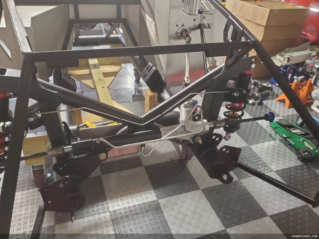
I like the look of the FF5 fluid reservoirs, so I decided to use three of those (I found my third reservoir in the “for sale” section of this forum) for my brake and clutch fluids instead of an aftermarket product. I made a bracket from 1/16” aluminum, and overlapped the cannisters’ clamps to try and make the assembly as compact as possible. I attached a length of 1” aluminum angle under the ¾” chassis tube, and then used two rows of 3/16” rivets to attach the bracket to the chassis tube and to the aluminum angle—it’s very sturdy. I used 6mm rivnuts and allen head bolts to attach the reservoir clamps to the bracket. I measure 11” from the footbox to the front end of the bracket (or, 22” from the front crossmember), so it should fit nicely. I mounted the backing plate to be parallel with the 4" chassis tube - I see now that it would have looked a bit better if I'd mounted flush with the 3/4" member, and made my reservoir clamps parallel with the 4" tube, but I'm happy with it. I'm not sure if the reservoirs are level with one another in this picture, but they are now. The rear most reservoir is for the rear brakes, the middle one for the front brakes, and the foremost one is for the clutch--easy for me to keep straight.


I had purchased nice brass bulkhead fittings to bring the fluid lines into the footbox. However, I just couldn’t justify drilling 3 more holes when I already had that big unused hole already there. So, I made this little cover plate (I used the scrap that I cut from the .090” firewall for the heater), drilled a hole for each hose, and ran them straight through without the bulkhead fittings.


I still don’t have my clutch master cylinder, so the rest of this assembly is on hold until I have all the pieces. I re-did my brake pressure lines, because I hated the way I originally had them. The front’s still the same as I previously posted, but I took out the coils going into the master cylinder. I Rre-ran the rear line down the inside of the footbox to an AN Bulkhead Elbow, then along the 4” member (those pics didn’t come out), and up to the ¾” crossmember.


After mounting my tires, it was obvious that I’d made a poor choice for my original location for the flexible brake line brackets, so I moved those outward. Finally, I replaced the NiCu line that I’d previously used with the FF5 supplied lines. I had originally wanted to avoid using a coupling, but I’m decidedly happier with the way I have it now, and the coupling will be easy to reach in case of a leak. The copper line was nice, but I just didn’t like the concept of using one type of material for the front line, and another for the rear, when it was all part of the same system. I could have changed the front to copper, but I like the look and hardness of the steel lines better. So, that was that. The NiCu wasn’t a complete waste—I used it to make templates before bending the FF5 supplied line. I also used the CuNi as a temporary hard line from the master cylinders to the reservoirs when I did my bench bleeding, so I got a bit of limited use from it.

Last edited by buttsjim; 03-14-2023 at 10:12 AM.
-
Post Thanks / Like - 0 Thanks, 1 Likes
-
Senior Member
Hi Jim. I like your cover plate. Turned out real nice. In hindsight, I would have placed my clutch reservoir in the same spot as you. At the time I was concerned about clearance. Mine is on my firewall, and will be more than a little inconvenient to reach now that I see it with the body on. Good choice on your part.
Chris
Coupe complete kit delivered: 4/22/24.
Build Thread. Coyote. T-56. IRS w/3.55. Wilwoods. PS. HVAC. Side windows.
MK4 Complete kit.
Build Thread Index. Delivered: 10/15/2020. Legal: 7/25/23. Coyote Gen3. TKO600 (0.64 OD). IRS w/3.55. PS. Wilwoods. Sway bars. This build is dedicated to my son, Benjamin.
Build Thread.
-
Senior Member
Originally Posted by
460.465USMC
Hi Jim. I like your cover plate. Turned out real nice. In hindsight, I would have placed my clutch reservoir in the same spot as you. At the time I was concerned about clearance. Mine is on my firewall, and will be more than a little inconvenient to reach now that I see it with the body on. Good choice on your part.
Thanks Chris--your comments are always very encouraging, and much appreciated.
-
Jim, this reminded me of some great advice I received from Mike Yager of MidAmerican Motors 15 years ago when I did my first frame off restoration on a 72 corvette. He said "when doing a build or restoration, don't have a budget or time frame because you'll blow right thru both of them and become frustrated". And I took his advice and it worked well since both happened. I'm enjoying reading your blog since I'm looking to order a MK4 this week. David
-
Senior Member
Originally Posted by
dherrenbruck
Jim, this reminded me of some great advice I received from Mike Yager of MidAmerican Motors 15 years ago when I did my first frame off restoration on a 72 corvette. He said "when doing a build or restoration, don't have a budget or time frame because you'll blow right thru both of them and become frustrated". And I took his advice and it worked well since both happened. I'm enjoying reading your blog since I'm looking to order a MK4 this week. David
Thanks, David! Good luck with your order, and upcoming build--your Corvette experience will serve you very well with the Cobra. I'm finding that there's a huge difference between being a "pretty good mechanic", simply diagnosing and replacing parts, and being a "builder", which takes a lot of forethought and careful planning--your prior experience will be extremely helpful in that regard. I don't have that experience, and it's constantly biting me in the butt. I'm looking forward to following your build.
Last edited by buttsjim; 02-13-2023 at 10:59 AM.
-
Senior Member
Flex Brake Line Questions
My brakes were bled, and I thought I was done with them until the go kart stage (please add that thought to my list of bad assumptions). After 4 rounds of bleeding, I had a nice hard pedal, without a trace of mushiness. So, I re-mounted my rear wheels, only to make a heartbreaking discoverythe flex line ferrules coming from the banjo fittings rubbed against the wheels. (I have the FFR 17 wheels and optional 13 FFR Mustang brakes). I was able to correct the left side by simply rotating the fitting, but the ferrule on the right side slanted straight up into the wheel, enough so that it dug in and scratched. I attempted to gently (really!) reduce the upward angle by tapping the ferrule down with a plastic mallet, but the fitting started to separate just when I was starting to make progress. Pumping the brake pedal confirmed that my tapping had created a minor leak at the ferrule.
So now the questions, and there are many. First, I cant figure out what size banjo bolt I haveI think its an M10x1.5, but it could just as easily be a 3/8 coarse thread. Does anyone know? Wrenches are no helpboth my 14mm and 9/16 wrenches fit the bolt head equally well. So, what size line do I need? Or, maybe since its sealed by the crush washers, it doesn't matter, and either a 10mm or 3/8 will work (thats another question). And, where can I find the flex line I needa 20 line with a straight ferrule and (I think), a 10mm banjo bolt. As an alternate to finding a different style line, has anyone ever mounted the FFR supplied line with the ferrule upside down? It seems like that might work. Maybe I routed my lines poorly and thats the problem; I ran them from the ¾ crossmember, behind the shock, to the caliper. Maybe I should have run them in front of the shock to the 3 member that the roll bars mount on? Any opinions on that? Finally, even if I get the required clearance for the wheels, Im only a quarter inch away from my rear springsis that enough?
Any advice is deeply appreciated. This is a small item, but leaky brakes is a critical issue that I need to resolve. And, I don't want my brake lines getting tangled up in my suspension. Thanks!
Last edited by buttsjim; 02-15-2023 at 04:13 PM.
-
Senior Member
Hi Jim. Sorry to read about your disappointing discovery. In my build, try as I might to plan well, unexpected stuff still happens. I'm not using banjo style connections as my brakes are Wilwood. I'm pretty sure I still have the banjo connections on the flexible braided lines that came with my kit. If these would be helpful to you, happy to send them your way (no charge).
Chris
Coupe complete kit delivered: 4/22/24.
Build Thread. Coyote. T-56. IRS w/3.55. Wilwoods. PS. HVAC. Side windows.
MK4 Complete kit.
Build Thread Index. Delivered: 10/15/2020. Legal: 7/25/23. Coyote Gen3. TKO600 (0.64 OD). IRS w/3.55. PS. Wilwoods. Sway bars. This build is dedicated to my son, Benjamin.
Build Thread.
-
Senior Member
Originally Posted by
460.465USMC
Hi Jim. Sorry to read about your disappointing discovery. In my build, try as I might to plan well, unexpected stuff still happens. I'm not using banjo style connections as my brakes are Wilwood. I'm pretty sure I still have the banjo connections on the flexible braided lines that came with my kit. If these would be helpful to you, happy to send them your way (no charge).
Thanks for the offer, Chris. I found some lines on Summit with straight ferrules, that will work perfectly, and I'm going to order those.
I'm enjoying following your body fitment, and it's going to be a great reference for me, one of these days!
-
Senior Member
This Might Work
Ain't she purty? It's Blueprint's injected 347 with the TKX. I took delivery before going to work this morning, and couldn't resist taking a peak at it before leaving. I'll uncrate it when I get home this evening, and check it over. Looking from the top, I didn't see any damage, and judging from the way it's crated I don't think there'll be any.

450 HP and 430 ftlb ought to be about enough. I'm very pleased with those numbers--they're higher than I was expecting. I opted for the .68:1 fifth gear, which will be plenty strong enough (for me, anyway) with that torque curve.

I'm not ready for the engine. It was scheduled for April delivery (not complaining!), but came early. I'm still fiddling with my e-brake, and haven't even started my wiring, so I'm not sure if I should put it in yet. I don't think it would be in the way if I installed it, but I'm suddenly feeling like I'm trying to rush things. However, it's currently sitting in my wife's parking space, and will create a diplomatic crisis if I don't do something with it pretty soon.
Last edited by buttsjim; 02-22-2023 at 03:20 PM.
-
Post Thanks / Like - 0 Thanks, 2 Likes
-
Senior Member
The Emergency Brake was an Adventure
I reversed the manual’s instructions when mounting the handle assembly. I placed the front bracket above the chassis mount and on the inside of the handle, and the rear bracket below its mount. I also cut just a tiny bit of the tunnel aluminum. Finally, I trimmed a bit off the short “L” on the anchor bolt to avoid it snagging on the carpet.

I considered running the cables per the manual and gluing a small sheet of Teflon on the 4” member to protect them from friction, but instead I borrowed from Edward B, Sunshine Garage and John Ibele, to end up with something like Fman’s result (nothing new under the sun, etc., etc.). The pulley I used required a 5/16” axle—I didn’t like the idea of drilling a hole that large in the chassis’ ¾” tube, so I used John Ibeles’ design for a bracket that I could rivet in place. Then, to gain a little extra clearance, I bolted extensions onto the brake handle’s lever arms, ala Sunshine Garage. I couldn’t source the Lokar clevis/cable clamp, so I made one from ½” aluminum bar stock (actually, I made 4—two ¾” stock and two ½” stock—before I was completely happy with the bar thickness and cable hole spacing).

(I'll clean that silicone bead off the aluminum before installing the engine)

When installed, the cables lined up at least an inch to the left of the brake handle’s lever arm. I tried to correct that by moving the pulley to the opposite side of my mounting bracket, but that location caused the cables to rub against the ¾” chassis tube. So, I took everything back out and re-worked the handle assembly with a spacer in the rod end’s proper position and the lever extensions and rod end all attached to the bracket's left side, instead of being centered. That gained me half an inch, and I let the rod end’s heim joint compensate for the remainder. I’m tempted to make a different cable clamp (#5!) with both of the cables run on the left side of the clamp and the threaded rod on the right (instead of centered), as an experiment. Doing so would line everything up just right, but I suspect that such an offset layout might create too much bending stress on everything. It’d be an interesting experiment though.

I ended up with two clicks total movement to lock my wheels, but with a very hard pull. I probably doubled the resistance with the extensions that I put on the lever arms (I think Fman took his back off for that reason), but some of that tightness might be due to the mis-alignment that I described. I’ve never noticed this in anybody else’s threads, but I can’t see where I’ve done anything wrong, other than my method for moving the handle away from the transmission tunnel. I’d appreciate any comments on that. Absent any suggestions for fixing or improving what I’ve done, I’m calling the job complete, and moving on to wiring.
Last edited by buttsjim; 03-03-2023 at 06:49 AM.
-
Post Thanks / Like - 0 Thanks, 2 Likes
-
Senior Member
By the way, I think the Lokar clamps might not be availale anymore. I'll mail my trial cable clamps (my first attempt went into the trash when I broke my tap in the last set screw hole, and I couldn't extract it) if anybody wants one. I'm not a machinist (obviously!) but they are servicable. They already have 4mm set screws installed, and the hole for the threaded rod is tapped to 1/4" - 28, same as the FF5 supplied rod end. PM me if you want one, and I'll pay postage (I'm not generous, it's just easier that way).


Last edited by buttsjim; 03-01-2023 at 06:39 PM.
-
Senior Member

Enjoying following along with your build. I have no specific comment ither than keep up the good work.
MK4 #10008 - Ordered 10/06/20, Delivered 03/03/21, First Start 7/22/21, First Go Kart 7/24/21
Paint by Metal Morphous 5/14/22, Legally registered 6/8/22, Graduated 7/20/22
Build Thread
https://thefactoryfiveforum.com/show...been-delivered
Complete Kit, Ford 306, Sniper/Dual Sync, T5, Hydraulic clutch


 Thanks:
  Likes:


 Reply With Quote


