-
Senior Member


Originally Posted by
Blitzboy54

Enjoying following along with your build. I have no specific comment ither than keep up the good work.
Thanks! It's very reassuring - and important - to know that experienced builders are looking over my shoulder!
Last edited by buttsjim; 03-03-2023 at 09:18 AM.
-
Senior Member
Transmission Mounting Question
Is this mounting tab on the TKX used for anything? There's interference between it and my e-brake mounting bracket, so that I can't align the transmission mount properly. I want to cut the tab off, but need to be sure the tab is unnecessary. I noted that the instruction manual said to cut off a mounting "boss" (but not on the TKX), but the boss that they showed was dirctly under the shift lever. This tab is about 8 or 10 inches forward of that point. I think that I can cut it off, but can someone with experience confirm it? Thanks!

-
Senior Member

No it's not used on the Cobra. Feel free to cut it off. It's what a lot of us did.
MK4 #10008 - Ordered 10/06/20, Delivered 03/03/21, First Start 7/22/21, First Go Kart 7/24/21
Paint by Metal Morphous 5/14/22, Legally registered 6/8/22, Graduated 7/20/22
Build Thread
https://thefactoryfiveforum.com/show...been-delivered
Complete Kit, Ford 306, Sniper/Dual Sync, T5, Hydraulic clutch
-
Post Thanks / Like - 0 Thanks, 1 Likes
-
Senior Member
Originally Posted by
Blitzboy54
No it's not used on the Cobra. Feel free to cut it off. It's what a lot of us did.
Great, that's what I thought, but it's good to be sure. Thanks!
-
Senior Member
Engine's in...Kind of
Although I wasn’t quite ready, I went ahead and put my engine in the chassis last week, and torqued all the mount fasteners. However, it’ll be quite a while before first start, because I’m not ready to do the wiring, throttle linkage, cooling system, etc. Also, I want to have an operational clutch before starting it, and I still don’t have my clutch master cylinder.
I had some friends lined up to help, but I ended up doing it by myself. The crated engine was sitting in my wife’s spot in the garage, so we had to leave her car outside. Wouldn’t you know it—the first hail storm we’ve had in maybe two years, picked that week to attack. Luckily, we got by with a medium dent in the roof and a small dent in a chrome strip (my last car to be attacked by hail was totaled!), but since more hail was expected the next night, I needed to do something.
So, out came the hoist, and in went the motor. Once I had the chassis positioned (I put the back about 16” higher than the front), the leveler attached, and the hoist ready, it took about 40 minutes to get it in. The only problems I experienced were that I had to remove the radiator to get the hoist close enough, and it took a bit of coaxing to get the left side motor mount into its slot in the chassis. A little bit of firm shoving took care of the latter. Once in place, I had some self-inflicted glitches getting all the fasteners torqued but, all in all, I think I had it all done in a little less than 3 hours, spent over a couple of days.
At least I thought I was done—I had forgotten to attach the grounding strap to the mount, so a bolt needed to come back out for that. I was a little concerned when I removed it, thinking the motor might shift, but I had no idea it would shift the way it did—when I pulled the bolt free, the motor gave a mighty “pop” and rotated at least half an inch counterclockwise. I couldn’t even see the mounting hole in the block, much less start the bolt back in. When originally mounting the motor, I didn’t tighten any fasteners until the motor was completely free of the hoist, so I don’t understand how I ended up with so much tension. Hopefully, that’s corrected now—I backed off all the remaining fasteners about a quarter inch, brought the hoist back out, and got everything to line up using very slight pressure. So, now I have a car with a motor that’s hopefully tension-free, and ready for all its accesories.
My photography skills are horrible, and these pictures don’t show how good the motor looks, sitting where it belongs. I’m quite happy with it, except for a very minor issue with a fitting on the power steering pump.


Last edited by buttsjim; 03-18-2023 at 08:35 PM.
-
Post Thanks / Like - 0 Thanks, 3 Likes
-
Senior Member

The Cobra is coming along really well considering all the missing parts. I may have missed it, but have you done the modification for the quick Jack or Overrider modification? If you don't you have to drop the tank to get the bolts in.
I hope to see you at the TCC Spring Meet in a couple of weeks.
Steve
Texas Cobra Club-Austin
July 2009 FFCars Picture of the Month
FFR3542K, 347 C.I., EFI, T-5, 3-Link, Miata Front Sway Bar, Red with White Stripes
-
Post Thanks / Like - 1 Thanks, 0 Likes
-
Senior Member
Thanks, Steve. Yep, I did the "Kleiner Mod" way back, when I was looking for stuff to do. The TCC Spring Meet would be a great opportunity to get involved in the Cobra community. I'm not sure if I can make it, but I hope so!
-
Senior Member

Sorry to hear about your wife's car, Jim. What unfortunate timing.
Congrats on getting your motor installed. I remember what a good feeling it is to see it in place. Did you put in the transmission as well, or is that coming later?
Chris
Coupe complete kit delivered: 4/22/24.
Build Thread. Coyote. T-56. IRS w/3.55. Wilwoods. PS. HVAC. Side windows.
MK4 Complete kit.
Build Thread Index. Delivered: 10/15/2020. Legal: 7/25/23. Coyote Gen3. TKO600 (0.64 OD). IRS w/3.55. PS. Wilwoods. Sway bars. This build is dedicated to my son, Benjamin.
Build Thread.
-
Senior Member
Originally Posted by
460.465USMC
Sorry to hear about your wife's car, Jim. What unfortunate timing.
Congrats on getting your motor installed. I remember what a good feeling it is to see it in place. Did you put in the transmission as well, or is that coming later?
Thanks, Chris. I was dissappointed about her car, since we had just bought it (used, but in perfect condition). But, I knew it could have been much worse, so I really did consider us to be lucky. Years ago, my 20 year-old perfect-condition RX-7 Turbo was totalled by baseball-size hail (reported by the news as such) while I was traveling to Shepard AFB. I finished the trip with huge dents, broken windows and windshield, and a broken heart for my dearly beloved. So, yep, we were lucky.
I put the engine and transmission in as a unit. The self-inflicted issues I had mentioned encountering all had to do with getting the transmission properly situated, mostly because of interference with the emergency brake brackets, which took some sawing and grinding. I put the driveshaft in the next day, so I now have a complete drivetrain. But, I'm a long, long way from first-starting or go-karting.
Last edited by buttsjim; 03-17-2023 at 07:45 AM.
-
Senior Member

Nice progress and a nice looking car taking shape, Jim. You won't regret having put the engine in and backing it out to do the wiring. It's a great chance to see what the space looks like, and where you're best off putting the wiring from battery to main cutoff and / or bus bar, and also to the starter. It looks like you have a Sniper sitting under that painters tape ... you'll want to think ahead so that you have the power wires for the Sniper going down to the battery as well. I had most of that scoped out pretty well before putting the engine in the first and only time, but I did have to sneak the Sniper wires down to the battery. Nothing's easy in that arena once the engine is in.
MK4 #7838: IRS 3.55 TrueTrac T5z Dart 347
The drawing is from ~7th grade, mid-1970s
Meandering, leisurely build thread is
here
-
Post Thanks / Like - 1 Thanks, 0 Likes
-
Senior Member
Originally Posted by
John Ibele
Nice progress and a nice looking car taking shape, Jim. You won't regret having put the engine in and backing it out to do the wiring. It's a great chance to see what the space looks like, and where you're best off putting the wiring from battery to main cutoff and / or bus bar, and also to the starter. It looks like you have a Sniper sitting under that painters tape ... you'll want to think ahead so that you have the power wires for the Sniper going down to the battery as well. I had most of that scoped out pretty well before putting the engine in the first and only time, but I did have to sneak the Sniper wires down to the battery. Nothing's easy in that arena once the engine is in.
Thanks, John! That's a great compliment coming from you, as I think your car is going to be stunning. I am stealing so many of your ideas and designs!
I was hoping to leave the motor in; in fact, I've put the driveshaft in, and was planning on installing my headers this week. Based on what you've said here, I guess I'll wait on the headers, and focus on my wiring. Between the Ron Francis instructions, the Blueprint wiring guidance, the Sniper instructions, Mark Reynolds' battery instructions, and everything I've read on this site, I am just totally confused, and have been stalling that phase of the project.
I'm really enjoying following your build, and looking forward to seeing your finished Cobra!
Last edited by buttsjim; 03-29-2023 at 03:28 PM.
-
Post Thanks / Like - 1 Thanks, 0 Likes
-
Senior Member
Originally Posted by
buttsjim
Thanks, John! That's a great compliment coming from you, as I think your car is going to be stunning. I am stealing so many of your ideas and designs!
I was hoping to leave the motor in; in fact, I've put the driveshaft in, and was planning on installing my headers this week. Based on what you've said here, I guess I'll wait on the headers, and focus on my wiring. Between the Russ Francis instructions, the Blueprint wiring guidance, the Sniper instructions, Mark Reynolds' battery instructions, and everything I've read on this site, I am just totally confused, and have been stalling that phase of the project.
I'm really enjoying following your build, and looking forward to seeing your finished Cobra!
Thanks for the kind comments ... but at the same time, remember I've got a grand total of 3/4 of a car built. Lots of others out there with more experience who may comment. And I always like to remind myself that there's often way more than one right way to do things. Having said that ... the way I did my wiring from battery up to starter, main cutoff, and bus wouldn't have been possible with the engine in. Similarly, I can't imagine putting the battery box in place without the room to move around standing in the engine bay.
I understand the comments about putting off wiring! I'm more mechanically inclined, and I didn't look forward to the wiring part. But as with anything, you steadily get better the more you do it, and fortunately it's tough to make big mistakes that are hard to correct. And once you get the hang of it, it can be kind of fun. Part of the trick is to take it step at a time. You don't need to understand it all at once, just the little bit you're doing now. And fortunately, if you test each circuit when you're done with it, you get immediate feedback and the satisfaction that comes when the test is successful. Spoken by a guy who recently was overwhelmed by the whole thing, and can remember the feeling.
Perhaps a few comments about order of only the items you mentioned will help.
- It's just fine having the harnesses in now, as the order in the manual calls for. In fact it's a great way to start to visualize how everything is going to come together.
- While the manual order is generally fine, if you have a front battery location you'll have some wiring that's hard to do after the engine is in place. Best to do it before the engine is in (or think about how you're going to work around that, and decide if it's worth it).
- Get the Breeze battery box in place, and for that matter, the battery. That will tell you exactly where your large cables need to start / terminate.
- Lay out your wiring that goes low on the frame that will be inaccessible with the engine in place. This should include anything mentioned by BP or Sniper regarding things that need to be connected directly to the battery (I don't know about BP, but Sniper has a few wires that should go directly there).
- Know where your ground straps are going to go. I go from battery straight to the frame, and from there to the engine, with a separate strap from frame to starter motor mount. Many other options work.
- Decide if you're going to take power to the starter post, main cutoff switch, straight to the remote solenoid (few do this anymore and I wouldn't recommend it) or to a bus bar (many do this, I did).
- Then you're back to the order in the manual. Drop the engine / drivetrain in.
- Tackle main wiring detailed in the Ron Francis manual. I wired the dash harness into my dash while it was on my workbench, tested everything I could there, then mounted it in the car.
- With the dash wired and in place and the engine in, you're in a great spot to connect the final wires up to sensors on the engine so the gauges work.
- And lastly, the Sniper wiring gets completed. These last two steps can go together since everything's accessible atop the engine.
It may have just been me, but somehow it helped to remind myself that every wire has a 'from' and a 'to' (pretty profound, I know...). When I got stuck, I found I often didn't have both of those clearly identified and in front of me on the car. Once I did, I knew what I was doing. You can apply this thinking to every single wire in the wiring diagram (and eventually you will, and will be done).
As always, use what helps here, and apologies for the rest of the needless rambling ")
Good luck!
Last edited by John Ibele; 03-18-2023 at 11:22 PM.
MK4 #7838: IRS 3.55 TrueTrac T5z Dart 347
The drawing is from ~7th grade, mid-1970s
Meandering, leisurely build thread is
here
-
Senior Member
Wiring
Originally Posted by
John Ibele
As always, use what helps here, and apologies for the rest of the needless rambling
Good luck!
It all helps...thanks!
I don't think well in the abstract--I do much better with things that I can see and touch. Therefore, having the engine in the chassis is pretty essential for me to be able to tie everything in with it. I hope to leave it in permanently but if it has to come out, it will have paid big dividends for the effort to put it in and take it out.
The Breeze battery box and battery are both in place so installing them isn't a problem. I'll trial route all the wires to their proper locations, and hopefull I'll have room to do so without having to pull the motor. I bought the buss bar recommended by EdwardB, but I have no idea what I'm going to do with it (the Blueprint guidance seems to want direct dedicated power to everything, and recommend against a buss bar for anything to do with the Sniper). I have a traditional solenoid mounted on the starter--the buss bar will probably be helpful with that as I think 3 large wires go there.
It's great advice to do one item at a time, test it, and move on, and I'm going to try and exercise the discipline to do so (once I get going, I tend to want to do everything at once). Likewise, everything else that you've stated--I'm probably going to do all that you've suggested. Right now, I'm just laying the harnesses out to visualize everything, and I'm re-reading all the various sources of instruction--I want the Sniper and Blueprint guidance firmly in the back of my mind while I'm wiring the Ron Francis harness so that I don't do something with item A that totally screws up what I need to do with item B.
Thanks again for looking over my shoulder and all that advice--it won't be wasted!
Jim B
-
Senior Member
Throttle Linkage
I waited until the motor was in before installing Forte’s throttle linkage. It took a bit of fiddling, but I ended up with great pedal feel, and the ideal (for me) ratio of throttle plate to pedal movement. I have the 0.09” firewall, which provided a solid mounting with no additional bracing necessary.

(I think that little bit of slope in the pivot shaft is an illusion)
I had a couple of issues (as always). I couldn’t use the bronze bushing I bought for running the pivot shaft into the pedal box. The idea was the pivot shaft into the bushing, the bushing into a grommet, and the grommet into the pedal box. Everything fit and it looked nice, but the pedal box wall was at too much of an angle to the pivot shaft. I had tried to size the hole and grommet to provide some leeway for this; the sizing helped to line everything up, but the forced alignment put too much pressure on the pivot shaft so that it didn’t rotate freely. I might have reduced that pressure with a bigger hole and grommet, but I didn’t want to keep drilling bigger holes, and then have it still not work. So, I just went with the pivot shaft in the grommet without any bushing. I smeared tire mounting compound in the grommet to eliminate friction, and I think it will last a while.
When all was assembled, I checked clearances in the footbox, and found that the lever arm couldn’t fully open the throttle without hitting the footbox cover. Why? I don’t know. I mounted the pivot shaft assembly about 1-1/4 inches above the 2x2 frame member—to mount it any lower I would have had to discard or file down the large washers provided for the inside of the firewall, so I’m not sure why the clearance issue (these types of issues always make me wonder what the heck I’m doing wrong).
The best fix I could see was to get the hacksaw and lop the top off the lever arm.
When I finished with the top-lopping, I tapped one side of its slot and used a 4mm screw and a spacer to maintain some sort of structural integrity. It’s not pretty, and not as “good as new”, but it’s solid, and it works well. The finished linkage has a smooth action and great feel to it, and I like it.
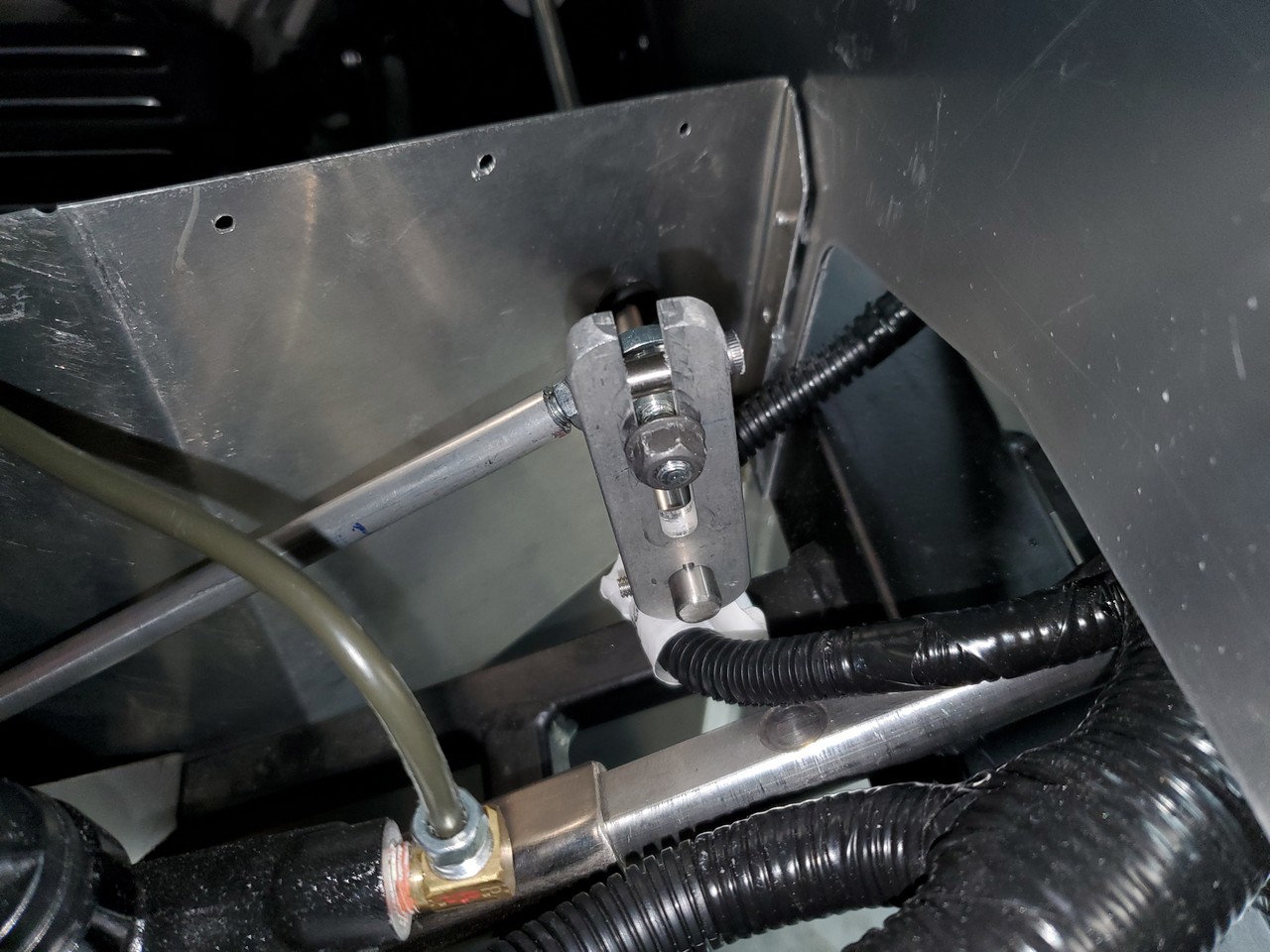
(that's the jamb nut visible on the left side of the lever arm (which is now tight)--not part of the 4mm screw which is cut flush with the lever arm. (with my photography skills, a word is worth a thousand pictures).
Last edited by buttsjim; 03-21-2023 at 10:21 AM.
-
Senior Member
-
Senior Member

shortening the rod between the pedal and linkage might have allowed you to rotate the arm inside the footbox down a bit, preventing the need to cut off the top. however, what's done is done and if it works, that's all that matters.
did you file a flat spot for the set screw in the arm? I ended up drilling and placing a roll pin in the lever after I was able to get the lever to slip with some firm pedal pressure. if you use a roll pin, leave a portion out on the footbox side in case you ever need to disassemble the linkage. trying to tap out a roll pin upside down in a finished car doesn't sound like fun.
-
Senior Member
Hmmm...I expect you're right, since no one else has had to cut their lever arm down. I tried a lot of different combinations of pedal location (forgot to mentiion that I have the Russ Thompson gas pedal, which works great with this linkage), lever arm angle, and rod lengths, and this combo worked best without hitting the footbox, firewall or chassis members. I played with things a bit after discovering the clearance issue, and decided that the lever arm would have to be in an almost horizontal position in order to get the required clearance. I didn't think the linkage would work smoothly in that configuration.
I hadn't thought of the lever arms slipping on the pivot rod. Filing a flat spot would be easy, but my setup doesn't use set screws; what you're seeing in the picture is the threaded end of a clamping screw--maybe Forte switched to that design because of slippage issues. I'll have to use roll pins. Forte provided two tiny diameter roll pins with the kit, I guess for this very purpose. And you're right--now's the time to do it. Thanks!
-
Senior Member
get a cobalt tipped bit, slow speeds, constant pressure, and plenty of cutting oil. drilling through the stainless steel rod is a bit of an adventure. you'll know when you get through the other side when the small chips of metal become a long thin ribbon of aluminum again.
-
Post Thanks / Like - 1 Thanks, 0 Likes
-
Senior Member
Removing Hot Rod Wiring (Steering Connector)
It seems like it would be good practice to remove the unused hot rod wiring from the harness, but I'm not sure of the ramifications. I assume that I'd need to remove the bundle from its conduit in order to pull the uneeded wires without disrupting the rest of the bundle. Do others normally do this? Or do you just tie that portion of the harness back as instructed in the manual? Likewise, there're other unused wires in other harnesses, that could probably be removed. Is doing so worthwhile--or is it overly anal? I'd appreciate some opinions regarding this.
-
03-23-2023, 10:06 PM
#100
Senior Member
Hi Jim. I'm just a novice, but I removed the hot rod wiring, as well as pretty much all unused wires and connections. Same for the Coyote harnesses, which I know don't apply to you. I liked the idea of having a "cleaner" wiring install. It also frees up precious space behind the dash. I'm sure the way the manual shows will work okay. It was just a preference for me. It definitely added time to my wiring phase, but maybe, just maybe if I need to troubleshoot a wiring gremlin someday, my efforts will pay off. I think this puts me in the overly anal camp. 
Chris
Coupe complete kit delivered: 4/22/24.
Build Thread. Coyote. T-56. IRS w/3.55. Wilwoods. PS. HVAC. Side windows.
MK4 Complete kit.
Build Thread Index. Delivered: 10/15/2020. Legal: 7/25/23. Coyote Gen3. TKO600 (0.64 OD). IRS w/3.55. PS. Wilwoods. Sway bars. This build is dedicated to my son, Benjamin.
Build Thread.
-
Post Thanks / Like - 1 Thanks, 0 Likes
-
03-24-2023, 12:53 AM
#101
Senior Member

Originally Posted by
buttsjim
It seems like it would be good practice to remove the unused hot rod wiring from the harness, but I'm not sure of the ramifications. I assume that I'd need to remove the bundle from its conduit in order to pull the uneeded wires without disrupting the rest of the bundle. Do others normally do this? Or do you just tie that portion of the harness back as instructed in the manual? Likewise, there're other unused wires in other harnesses, that could probably be removed. Is doing so worthwhile--or is it overly anal? I'd appreciate some opinions regarding this.
I left all the existing wiring and just covered the connection up with gorilla tape. Not the best looking results but I was afraid of screwing something up removing wires. Definitely a cleaner look doing it like 460.465USMC, I just did not trust my dieting skills 
-
Post Thanks / Like - 1 Thanks, 0 Likes
-
03-24-2023, 05:16 AM
#102
Senior Member

Originally Posted by
buttsjim
It seems like it would be good practice to remove the unused hot rod wiring from the harness, but I'm not sure of the ramifications. I assume that I'd need to remove the bundle from its conduit in order to pull the uneeded wires without disrupting the rest of the bundle. Do others normally do this? Or do you just tie that portion of the harness back as instructed in the manual? Likewise, there're other unused wires in other harnesses, that could probably be removed. Is doing so worthwhile--or is it overly anal? I'd appreciate some opinions regarding this.
The hot rod connector and related wiring can be removed without affecting anything else. Just make sure to do it properly because those are live wires. If you look at the schematic you can see that they're parallel connections to other active wires in the harness. You can cut them off where they enter the harness. Or you can strip back the convolute and get at or near the source. I don't recommend the latter unless you're 100% confident of what you're doing. Make the wire cuts offset (so none are possible to touch the end of another) and cover the ends with shrink sleeving (ideal) or electrical tape. As for other unused wires, unless you're really pressed for space, I'd probably leave them alone unless you're comfortable reading the schematic and understand exactly what they are. The RF harness is a decent fit for the Roadster and unless you're really packing things behind the dash, fits without too much effort. It's a little different for the Coupe, and quite a bit different for the Hot Rod and Truck. But that's a different story.
Build 1: Mk3 Roadster #5125. Sold 11/08/2014.
Build 2: Mk4 Roadster #7750. Sold 04/10/2017.
Build Thread
Build 3: Mk4 Roadster 20th Anniversary #8674. Sold 09/07/2020.
Build Thread and
Video.
Build 4: Gen 3 Type 65 Coupe #59. Gen 3 Coyote. Legal 03/04/2020.
Build Thread and
Video
Build 5: 35 Hot Rod Truck #138. LS3 and 4L65E auto. Rcvd 01/05/2021. Legal 04/20/2023.
Build Thread. Sold 11/9/2023.
-
Post Thanks / Like - 1 Thanks, 0 Likes
-
03-24-2023, 05:29 AM
#103
Senior Member
Originally Posted by
edwardb
You can cut them off where they enter the harness. Or you can strip back the convolute and get at or near the source. I don't recommend the latter unless you're 100% confident of what you're doing. ... The RF harness is a decent fit for the Roadster and unless you're really packing things behind the dash, fits without too much effort.
Thanks everyone for your advice--it's just what I was seeking. I think I'm going with Paul's suggestion to stagger cut the hot rod wires, and leave the rest alone. Thanks again for your inputs!
Last edited by buttsjim; 03-24-2023 at 07:54 AM.
-
03-25-2023, 07:32 AM
#104
Senior Member
Originally Posted by
buttsjim
It's a lesson learned: don't take good workmanship for granted, regardless of the supplier—everything needs to be checked out and, the sooner the better!
It's good you're onto this early in your build. When I started this project years ago I had never run across the term 'blueprinting' before. It takes time to verify proper operation of each component, and very few have the tools and expertise to test absolutely everything before they put it on the car. But it's worth the time to test what you can, verify proper operation and setup, and often, improve what came out of the box before you put it on the car. While it takes time, it sure saves headaches later when everything has to work at once, on demand.
MK4 #7838: IRS 3.55 TrueTrac T5z Dart 347
The drawing is from ~7th grade, mid-1970s
Meandering, leisurely build thread is
here
-
Post Thanks / Like - 0 Thanks, 1 Likes
-
04-14-2023, 06:52 PM
#105
Senior Member
Quick Question
I was removing the 3 ground wires from my RF sensor harness, with the thought of grounding them near the fuse box. I wanted to lighten the bundle going to the engine compartment, in order to redirect a couple of other wires into that bundle. I found that the 3 wires I wanted to remove actually tied into 1 wire of the same guage coming from the connector. I can understand finding 3 wires from the connector going into one to the ground point, but not vice-versa. It seems to me that once I establish a good clean ground, it would be adequate for all three wires, but the fact that RF has split that single ground into 3 branches tells me that establishing 3 separate grounds is important. Is this correct? Thanks for any and all advice regarding this, as I'm probably going to run into the same situation elsewhere.

-
04-14-2023, 09:49 PM
#106
Senior Member

probably for reliability. I have not seen the harness, electrically it would not matter unless there is reason to put one on the engine, and a couple on the frame at different points to ensure there is always a ground and not single point.
-
Post Thanks / Like - 1 Thanks, 0 Likes
-
04-14-2023, 10:38 PM
#107
Senior Member
Originally Posted by
F500guy
probably for reliability. I have not seen the harness, electrically it would not matter unless there is reason to put one on the engine, and a couple on the frame at different points to ensure there is always a ground and not single point.
Thanks for that, and it's kind of what I was thinking. However, it just occurred to me that the harness might be done this way to provide for sensors that have two terminals (12V and ground), rather than being grounded by the sensor body. That would make sense, assuming there are such sensors.
-
04-15-2023, 05:41 AM
#108
Senior Member
Both answers are correct. Multiple grounds for reliability (how many threads end with a solution "bad ground"?) and to have grounds for sensors if required. I wouldn't remove anything until you're positive to have everything covered. Older versions of the RF harness had IMO (and others) minimal ground connections. The latest ones are much better.
Build 1: Mk3 Roadster #5125. Sold 11/08/2014.
Build 2: Mk4 Roadster #7750. Sold 04/10/2017.
Build Thread
Build 3: Mk4 Roadster 20th Anniversary #8674. Sold 09/07/2020.
Build Thread and
Video.
Build 4: Gen 3 Type 65 Coupe #59. Gen 3 Coyote. Legal 03/04/2020.
Build Thread and
Video
Build 5: 35 Hot Rod Truck #138. LS3 and 4L65E auto. Rcvd 01/05/2021. Legal 04/20/2023.
Build Thread. Sold 11/9/2023.
-
04-15-2023, 06:55 AM
#109
Senior Member
Originally Posted by
edwardb
Both answers are correct. Multiple grounds for reliability (how many threads end with a solution "bad ground"?) and to have grounds for sensors if required. I wouldn't remove anything until you're positive to have everything covered. Older versions of the RF harness had IMO (and others) minimal ground connections. The latest ones are much better.
Thanks, Paul. My original thought was to ground all three of those wires at a single point near the fuse box. Seeing that all three went back to a single wire gave me second thoughts about that idea. My plan is fine if the reason for the split is to accomodate sensors with two terminals, but not if the split is there for reliability. I still plan to remove the ground wires from the sensor harness tubing, but will come up with a grounding method that ensures long-term reliability. Thanks again--I really appreciate your checking out my thread and offering your advice.
-
08-10-2023, 07:10 PM
#110
Senior Member
My goodness, its been forever since Ive been on this forum, either to post, or to read about anyone elses progress. Likewise, Ive done very little on the car, and Im not a whole lot farther along than when I last posted. I havent spent much time on the Cobra and when I do, my efforts are randomI seem to spend 95% of my time thinking and looking, and 5% actually accomplishing anything, so no progress. In April, I was on an easy schedule to attempt my first start on Memorial DayI not only missed that target, but Im still at least a month away. Indecisiveness, frustration, confusion, apathy, low energy, time, and competing priorities are to blame. Not to mention that Im lazy. And now, due to a job change, Im only home on weekends, so Im having to squeeze in my Cobra work amongst a zillion things to do around the house.
When I quit on the Cobra, I was about halfway done with the wiring. Now that Ive picked it back up, I see that Ive forgotten where I was going with my wiring plan, so Im having to learn that all over again. As a result, Ive just been doing a little wiring at a time and completing other tasks while I think about the wiring. This picture gives an overview of my progress to date (its a mess). Ill try and catch this thread up with a few posts re-capping what Ive done to get there without going into a lot of detail, which would make for extremely long and boring posts. Ill try to describe it in the same order in which I did the work.

-
08-10-2023, 07:22 PM
#111
Senior Member
I received a replacement for my faulty Pro M hanger (see post #95) and installed it. I was irked by Pro Ms indifference to having sent out an obviously defective part and then making me pay to return it, but they replaced it promptly, and its now all back together and properly wired. I used Perm Seal butt connectors for the pump wiring, as theyre highly recommended on this forum. By the way, for all other permanent wire connections, Im using heat shrink butt connectors that have the low temp solder ring, and Im using Weather Packs for everything that needs to be dis-connectable (I think I just made that word up). The butt connectors are strong (I cant pull them apart), and have a very low resistance, and the Weather Packs are fun to assemble, and they provide a secure connection. Im happy with both of those items.
Ive installed my Gas-N headers and, like always, I encountered a few problems. The most time-consuming issue was aligning the bolt holes in the header flanges with those in the heads. Georgie warned in the instructions to make sure all the bolts would thread in before installing the engine. I did this, but wanting to grind the minimum metal from the flanges, I got the bolts to where they would just barely fit in. Well, this didnt work with the engine in the chassisthere was one bolt on each bank that just refused to thread in easily. Not wanting to strip/cross the threads in the heads, I was super cautious, and ended up trial fitting each side 3 or 4 times before finally grinding away enough of the flange to get all the bolts to thread in easily. Then, there was a problem with the numbers 1 and 8 spark plugs; there wasnt enough clearance to get a socket on them, so I had to grind away even more of the flanges to get a halfway decent shot at the plugs. I ground away as much as I dared on the flange, and then ground down the end of a thin wall spark plug socket and drilled out its inner plug retainer to make it wobble. The modified socket did the trick.

Georgie provided all necessary gaskets and hardware, but I decided to go with Remflex gaskets and, because Id ground so much off the header flanges, I opted for an ARP header bolt set that came with thick washers, rather than using the set provided by Georgie.
My first trial fit of the headers showed that my plug wires were contacting them, so I decided to use heat wrap. I hated to cover those beautiful headers but decided I preferred ugliness to melted plug wires. Id never used heat wrap before, but it wasnt difficult, although I think I could have done a nicer job with a little 20/20 hindsight. Nevertheless, Im satisfied.
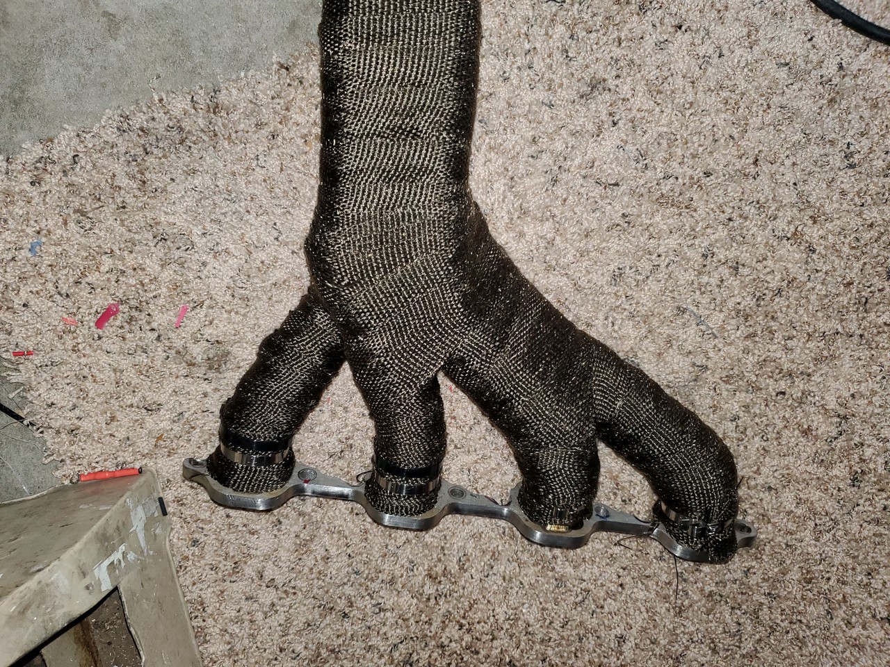
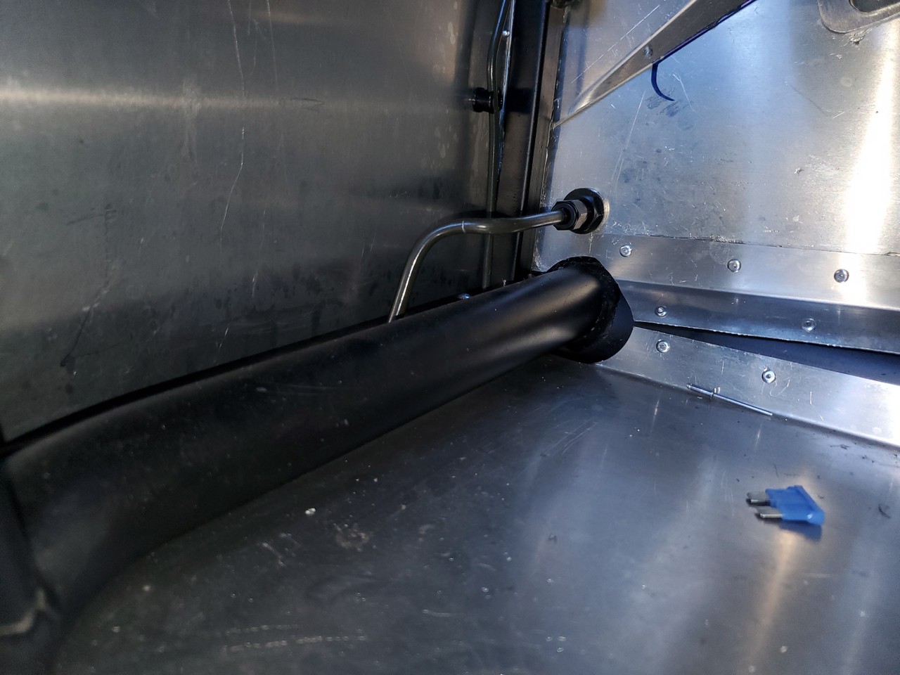
I was also concerned that the headers were only about two inches away from where my hard fuel lines from the tank connect to the flex lines to the Sniper. I put a bit more bend in the hard lines to move them a couple more inches away, but theyre still closer than Id like. I might need to put some sort of shielding over them.
-
08-12-2023, 06:04 PM
#112
Senior Member
Here's some more work that I did in April (I'm catching up my thread):
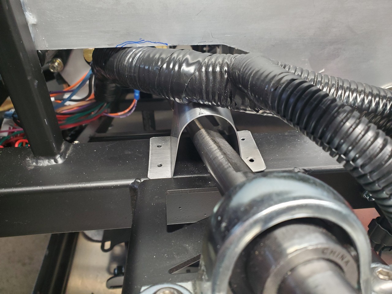
I received my steering wheel from FFR in April, so I assembled my Russ Thompson steering mod and checked it all out—it fit, but the dash didn’t (more on that later). I will be using the turn signal stalk to dim my headlights, and bought the relays for that, but haven’t wired them yet. I made a little hoop to go over the steering column, so that the wiring harness would lay on that instead of the column. I cut an arc along that blue Sharpie line to give the harness a bit more breathing room. And, that glob of silicone is now gone. I need to start removing silicone before taking pictures, instead of afterwards. I get rid of all the residue after it hardens, but I think my pictures give a bad impression.
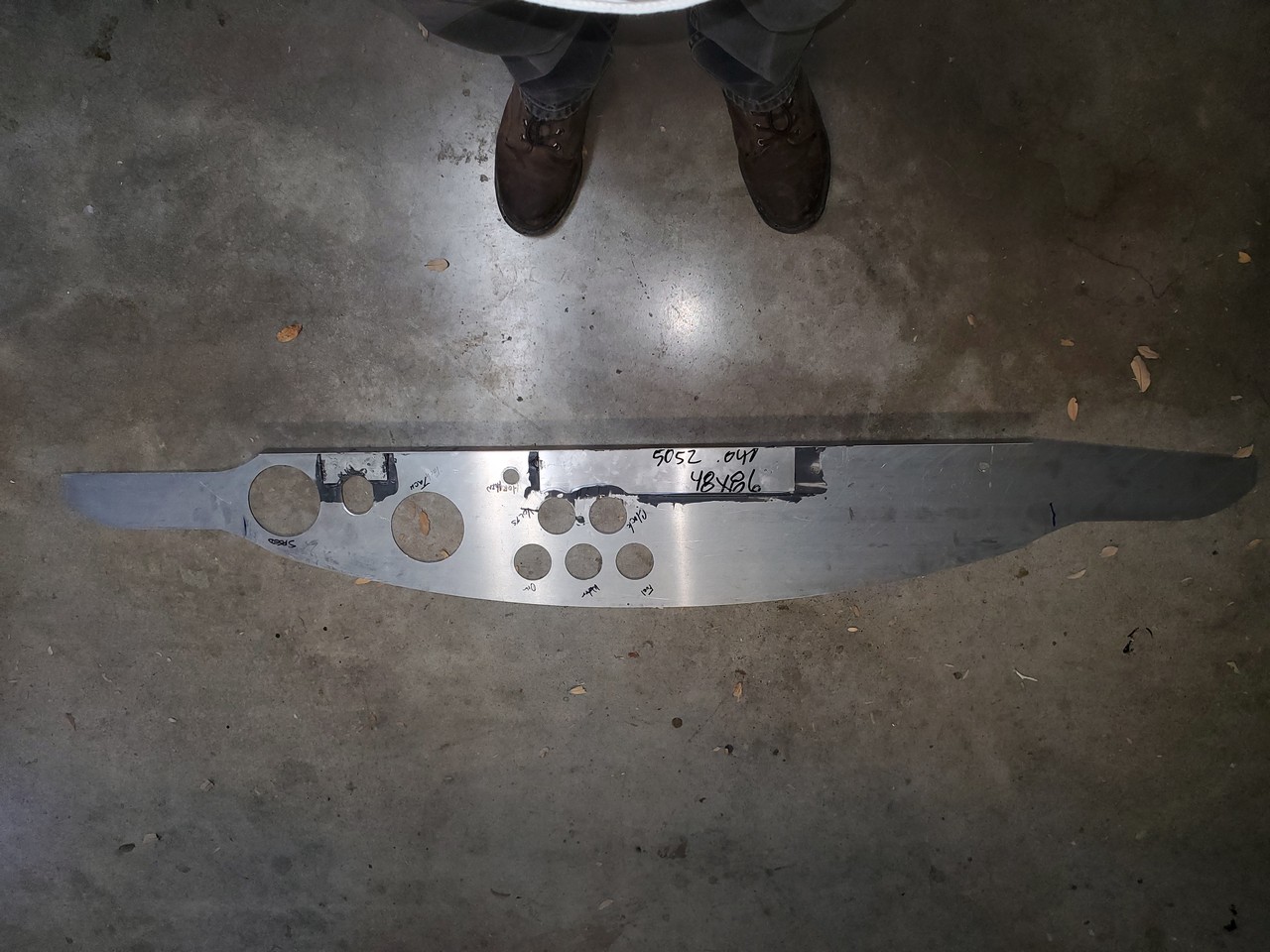
Now the dash—I didn’t properly do my homework before ordering my kit, and assumed that the dash would be blank since that was what I’d seen in the forum threads I’d been reading. I was a little disappointed to receive a dash with all the cutouts already made, but decided it wasn’t a big deal since I didn’t have a clear idea/preference of how I wanted my layout anyway. However, the factory cutout for the tach interfered with the ¾” tubing in that area, and the oval hole for the steering column was too low. I fixed both issues by extending the oval ½” upward, and filling in a ½” at its bottom, which allowed me to lower the dash to its proper location.


I need to drill a few holes for the toggle switches and make a decision on my heater control before starting to cover the dash. The heater control is an issue, as it’s ugly and doesn’t match with the headlight switch. I could hide it facing downward at a 45* angle in a lower dash brace, but this puts a severe bend in the cable making it hard to open and close the heater valve. So, I need to decide between looks or functionality.
I made two braces to support the lower part of the dash, and brackets to connect the grab handle to the 3” square tube. I also JB Welded a backing plate to the dash for the ignition and headlight switches because I didn’t like the way they fit in their pre-drilled holes.
Last edited by buttsjim; 08-24-2023 at 07:24 AM.
-
Post Thanks / Like - 0 Thanks, 1 Likes
-
08-13-2023, 11:26 AM
#113
Senior Member
Welcome back, Jim. Good to read you are able to get in a little build time here and there. I like the hoop you made to protect the wiring from contacting the upper steering shaft. Nice!
Chris
Coupe complete kit delivered: 4/22/24.
Build Thread. Coyote. T-56. IRS w/3.55. Wilwoods. PS. HVAC. Side windows.
MK4 Complete kit.
Build Thread Index. Delivered: 10/15/2020. Legal: 7/25/23. Coyote Gen3. TKO600 (0.64 OD). IRS w/3.55. PS. Wilwoods. Sway bars. This build is dedicated to my son, Benjamin.
Build Thread.
-
Post Thanks / Like - 1 Thanks, 0 Likes
-
08-13-2023, 05:47 PM
#114
Senior Member
Originally Posted by
460.465USMC
Welcome back, Jim. Good to read you are able to get in a little build time here and there. I like the hoop you made to protect the wiring from contacting the upper steering shaft. Nice!
Thanks Chris...you're always so encouraging! I hadn't been on the forum for several months, but will be catching up on your thread later today.
-
08-13-2023, 08:19 PM
#115
Senior Member
Catching up (April Tasks)
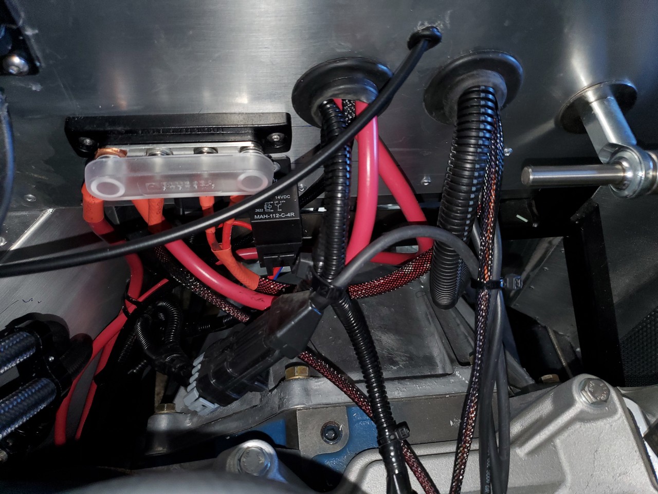
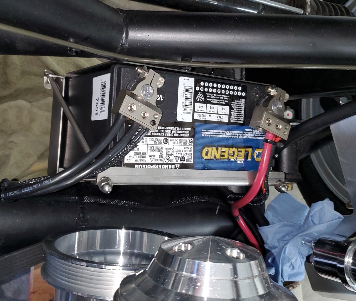
I mounted a buss bar and the Sniper fuel pump relays near the center of the firewall in the engine bay. My electrical power runs from the battery to the cutoff switch inside the cockpit, and then back out to the buss, from where its distributed. I had a 10 pin connector from the Sniper in that area that had only one wire, so I cut that connector off and replaced it with a single pin Weather Pack. Im trying hard to get a clean look in the engine bay, but this area looks nasty. Some people have a knack for doing nice clean wiring jobs, but my knack is for making a rats nest out of a two-wire circuit.
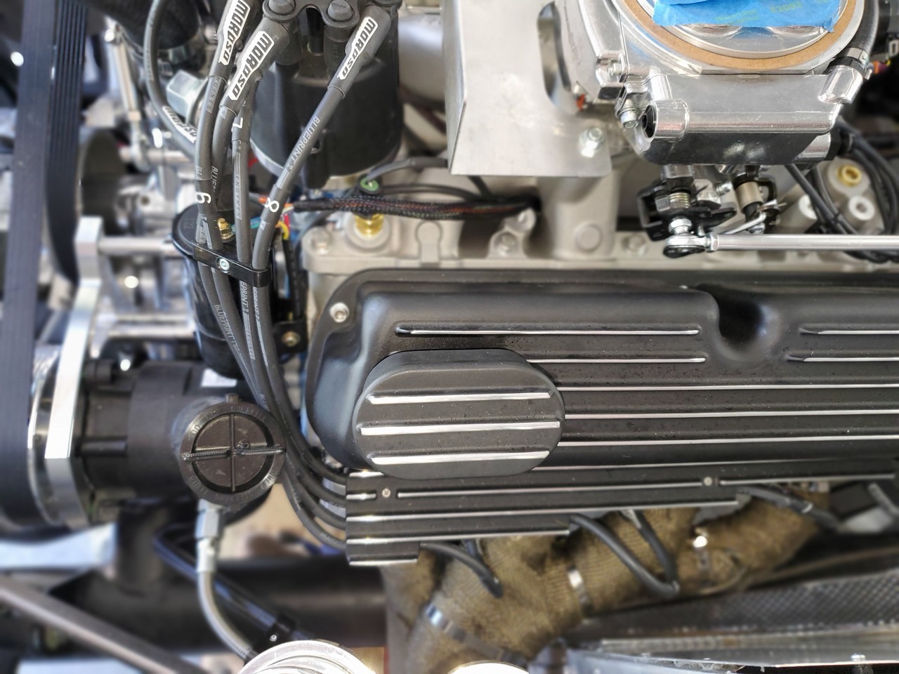
I liked the oil pressure and water temperature sending units and wiring that came with the gauges, so I opted to use those instead of the Ron Francis wiring for those items. I stripped the appropriate RF wires and pins from the harness and ran the gauge wires under the intake manifold to their respective sending units. I checked with Dan Golub about this alternative and was told that others had done the same, so I dont anticipate any problems with it. This is a horrible picture but you can sorta-kinda see the wire to the water temp sensor, as well as the two wires to the coil. The wire to the oil pressure sensor is there as well, but I dont think you can really see it.
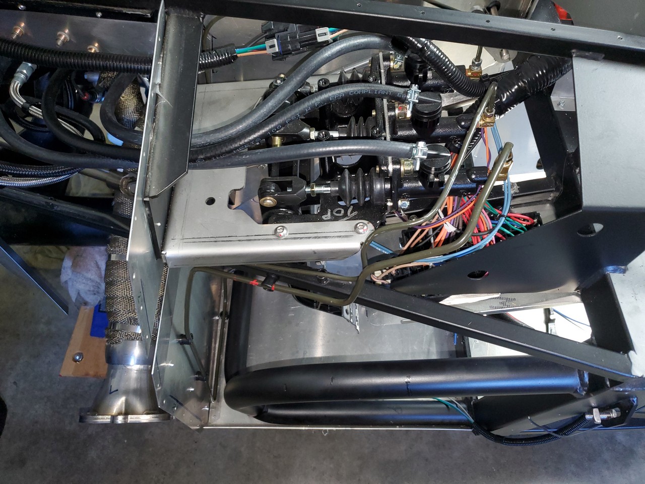
I finally received my long-awaited clutch master cylinder from FFR, so my final task in April was to install it and run the hard line. I routed the line from the MC to the front of the foot box, then down and over to the transmission tunnel, where I used a 4AN bulkhead elbow fitting for the flexible line to the clutch. Looking at it today, I dont remember why I have the line so far out from the footbox panelit doesnt interfere with my pedal movement or foot space, but it will be awkward when it comes time to install the carpeting. I remember the comedian Red Skelton once saying after a bad joke, I just do em, I dont explain em!, and sometimes I think that should be my mantra with this project. Regardless, Im loving it.
-
08-17-2023, 03:45 PM
#116
Senior Member
Some May Accomplishments
I accomplished a variety of small tasks in May. In the wiring arena, I have it in my notes that I modified my rear harness to plug in my fuel pump and fuel level sender. I dont remember why I did this, what I did, or if it was even necessary, but I must have done it because its in my notes. I also extended the Sniper power wire to enable it to run along the 4 chassis member to the battery a little more neatly. I installed my master cutoff switch onto a lower dashboard bracket that Id made, and as mentioned earlier, brought my power into the switch, and then back out to the buss. I ended that months electrical work by installing battery terminals that I found on Amazon. These terminals have multiple inputsboth for large gauge and smaller gauge wires, so I used most of them. As a result, I have lots of redundancy, such as two power wires for the Sniper (both connecting to the exact same place) and multiple grounds for the negative side. Its probably silly, useless overkill, but I had the means to do it, so I did. Sometimes when you do stuff like that you just create more opportunities for things to go wrong, but I dont think thats the case in this instance.
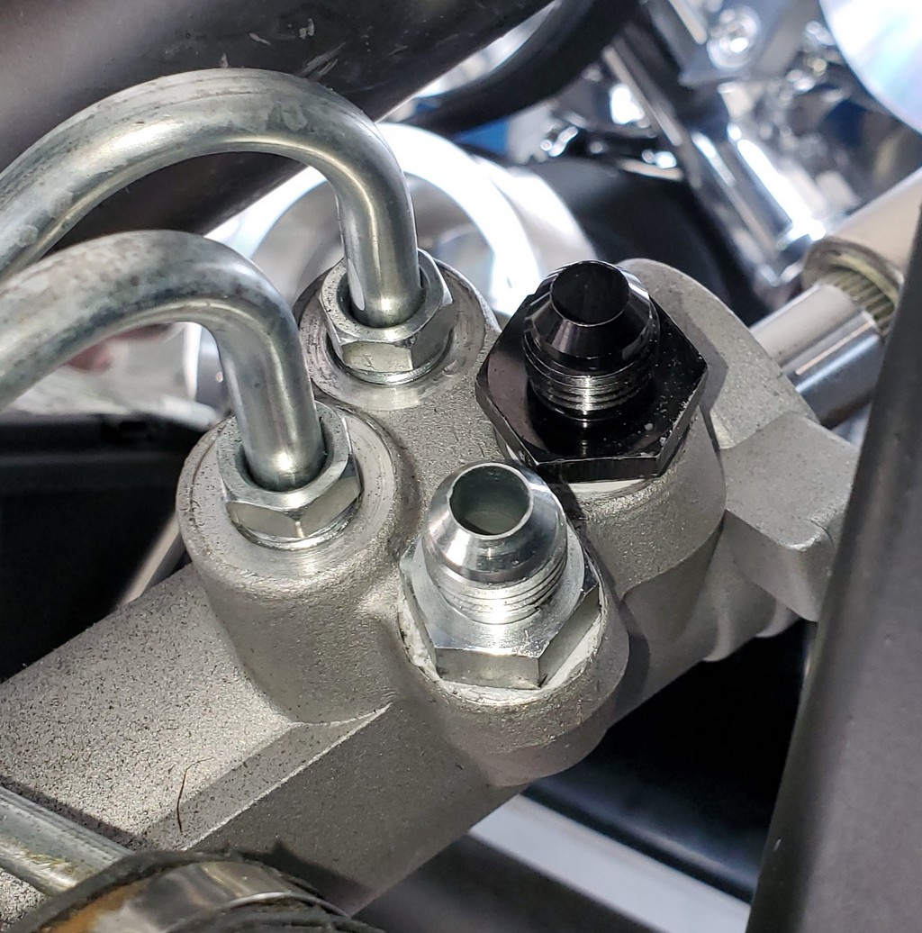
I had some trouble with the power steering lines. I was expecting 20-minutes to complete this task, but it took several days before I had them in and, Im still not confident that the return fitting wont leak. I had a fit getting that fitting to fit, and I just dont understand it. The high-pressure line took about 5 minutes, and it was done. But the fitting that I had for the return port wouldnt even turn in a full turn. I took a picture and sent it to Dan G at FFR, and he provided the fitting specifications. I ordered that fitting to be sure I had the right one but nope, it didnt fit either. I then spent hours looking through my kit parts for a fitting that would fit and found nothing in the parts provided with the kit. Eventually, I tried an AN conversion fitting that Id mistakenly purchased for some reason, and it was close, turning in about 4 turns (I dont remember what type of fitting the non-AN side was. I thought this fitting would work, but since it didnt screw in very far, I had clearance issues above it. I tapered the bottom 1/4 of the fitting so that those first few threads wouldnt engage tightly (only those threads at the top portion of the fitting would engage), which allowed me to turn it all the way in. So, its in, its tight, and it looks like its supposed to look, but theres a fair chance that it will leakI think the pressure gets up to about 100 psi on the suction side of the system, so the opportunity is there. If it leaks, Ill have to pull the rack and take it to a machine shop. Well see.
-
08-17-2023, 04:17 PM
#117
Senior Member
Originally Posted by
buttsjim
I received a replacement for my faulty Pro M hanger (see post #95) and installed it. I was irked by Pro M’s indifference to having sent out an obviously defective part and then making me pay to return it, but they replaced it promptly, and it’s now all back together and properly wired. I used Perm Seal butt connectors for the pump wiring, as they’re highly recommended on this forum. By the way, for all other permanent wire connections, I’m using heat shrink butt connectors that have the low temp solder ring, and I’m using Weather Packs for everything that needs to be dis-connectable (I think I just made that word up). The butt connectors are strong (I can’t pull them apart), and have a very low resistance, and the Weather Packs are fun to assemble, and they provide a secure connection. I’m happy with both of those items.
I’ve installed my Gas-N headers and, like always, I encountered a few problems. The most time-consuming issue was aligning the bolt holes in the header flanges with those in the heads. Georgie warned in the instructions to make sure all the bolts would thread in before installing the engine. I did this, but wanting to grind the minimum metal from the flanges, I got the bolts to where they would just barely fit in. Well, this didn’t work with the engine in the chassis—there was one bolt on each bank that just refused to thread in easily. Not wanting to strip/cross the threads in the heads, I was super cautious, and ended up trial fitting each side 3 or 4 times before finally grinding away enough of the flange to get all the bolts to thread in easily. Then, there was a problem with the numbers 1 and 8 spark plugs; there wasn’t enough clearance to get a socket on them, so I had to grind away even more of the flanges to get a halfway decent shot at the plugs. I ground away as much as I dared on the flange, and then ground down the end of a thin wall spark plug socket and drilled out its inner plug retainer to make it wobble. The modified socket did the trick.
Georgie provided all necessary gaskets and hardware, but I decided to go with Remflex gaskets and, because I’d ground so much off the header flanges, I opted for an ARP header bolt set that came with thick washers, rather than using the set provided by Georgie.
My first trial fit of the headers showed that my plug wires were contacting them, so I decided to use heat wrap. I hated to cover those beautiful headers but decided I preferred ugliness to melted plug wires. I’d never used heat wrap before, but it wasn’t difficult, although I think I could have done a nicer job with a little 20/20 hindsight. Nevertheless, I’m satisfied.
I was also concerned that the headers were only about two inches away from where my hard fuel lines from the tank connect to the flex lines to the Sniper. I put a bit more bend in the hard lines to move them a couple more inches away, but they’re still closer than I’d like. I might need to put some sort of shielding over them.
FYI, I bought some heat retardant boots that fit over the spark plug wires that shields them from the headers. Just in case you want to show off your Gas-N ones.
-
Post Thanks / Like - 1 Thanks, 0 Likes
-
08-17-2023, 06:04 PM
#118
Senior Member
Originally Posted by
egchewy79
FYI, I bought some heat retardant boots that fit over the spark plug wires that shields them from the headers. Just in case you want to show off your Gas-N ones.
Thanks! I'd be very interested in the heat retardant boots. Can you post the info?
-
08-17-2023, 07:26 PM
#119
Senior Member
-
Post Thanks / Like - 1 Thanks, 0 Likes
-
08-17-2023, 08:30 PM
#120
Senior Member
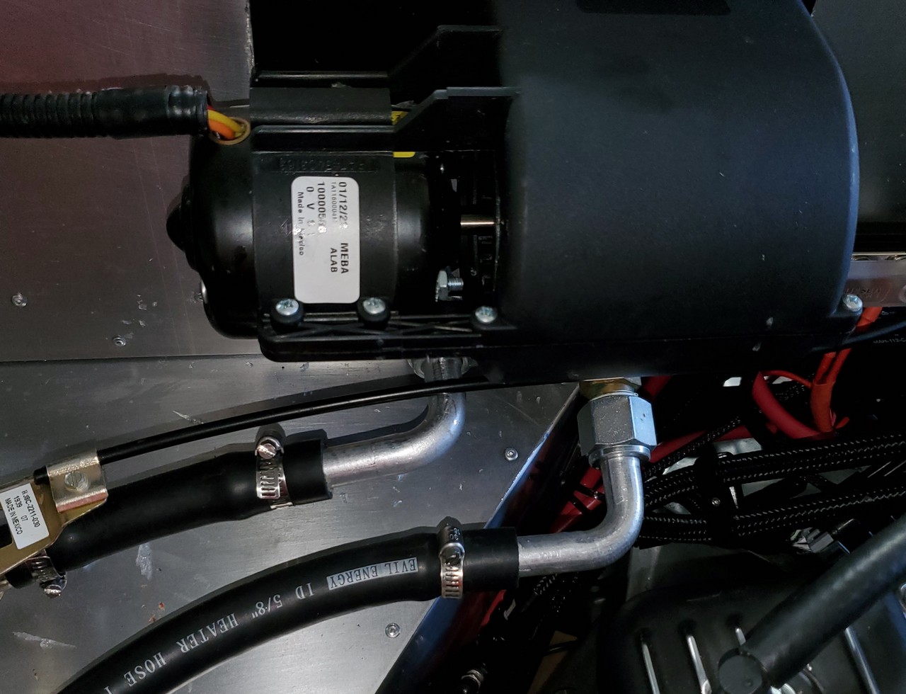
I regret ordering the heater with my kit, and further regret immediately doing the cut-out for it in the firewall. The heater and hoses clutter up the engine bay, the heater cabinet is very cheaply made, the control looks cheap and is hard to locate, and I really don’t need the thing in the first place. If I hadn’t made the cut-out in the firewall, I could have not installed it, and tried to sell it. But the holes in the firewall committed me, so I made the best of it.
The heater fan assembly attaches to the coil housing through the firewall using 6 small sheet metal screws screwed into 1/16” plastic. I didn’t trust that, so I put small strips of metal with riv-nuts inside the coil housing and used small button head screws to hold the two halves together. It looks nice, and it’s much stronger.
I had a self-inflicted adventure with the heater coil. I thought that the two ½” tubes from the coil (the stub-outs that connect to the aluminum 90* elbows) should be staggered, and I didn’t anticipate any problems in making them that way. I’ve sweated lots of plumbing fittings—I’d learned how to properly do it in high school many years ago; I’d never had one to leak, and this job looked like more of the same. My plan was to cut a couple of inches off the outboard stub-out, de-solder the fitting from the portion I’d cut off, and then solder that fitting back to the shortened stub out from the coil. Easy-peasy, I thought, but apparently there’s a pretty low limit to my plumbing expertise—I couldn’t de-solder the fitting! I had it red hot using a MAAP torch but never fazed the soldering, which must have actually been welding. As a backup, I could have cut a short section from the middle of the stub-out, and then rejoined the two pieces with a half inch coupling. However, I’d used vise grips trying to separate the tubing from the fitting and deformed it beyond any hope of reusing. I went through all my plumbing parts looking for a replacement fitting but couldn’t find anything that was compatible to the one on the elbow. The next day I managed to walk into Ferguson’s Plumbing Supply when only the counterman was there, so we spent a good 20 minutes going through the aisles looking for the perfect fit. A 5/8” MIP came very close—it threaded, but it didn’t seem like a firm fit until it was screwed all the way in. Luckily, that joint seals with an “O” ring, so I went with the 5/8” MIP, and put in a thicker “O” ring to ensure a good seal. I also used multiple layers of Teflon tape on the threads to tighten up the joint as much as possible (I’m using Teflon tape on all my water connections, and Permatex Thread Sealant on everything else). I’m very sure the joint won’t leak, but it might not remain tight if vibrations are present once the car is started. It’s another wait and see situation. The picture shows the aluminum elbows after staggering, but check out the wires coming from the fan motor—that’s the way it came and it's what I’m talking about when I say the heater seems cheaply made.
Last edited by buttsjim; 08-19-2023 at 05:11 PM.


 Thanks:
  Likes:


 Reply With Quote


